EP3045925A1 - Procédé et système pour déterminer un état de charge de manière itérative d'une cellule de batterie - Google Patents
Procédé et système pour déterminer un état de charge de manière itérative d'une cellule de batterie Download PDFInfo
- Publication number
- EP3045925A1 EP3045925A1 EP16151330.4A EP16151330A EP3045925A1 EP 3045925 A1 EP3045925 A1 EP 3045925A1 EP 16151330 A EP16151330 A EP 16151330A EP 3045925 A1 EP3045925 A1 EP 3045925A1
- Authority
- EP
- European Patent Office
- Prior art keywords
- soc
- selected cell
- predicted
- controller
- sev
- Prior art date
- Legal status (The legal status is an assumption and is not a legal conclusion. Google has not performed a legal analysis and makes no representation as to the accuracy of the status listed.)
- Granted
Links
Images


Classifications
-
- G—PHYSICS
- G01—MEASURING; TESTING
- G01R—MEASURING ELECTRIC VARIABLES; MEASURING MAGNETIC VARIABLES
- G01R31/00—Arrangements for testing electric properties; Arrangements for locating electric faults; Arrangements for electrical testing characterised by what is being tested not provided for elsewhere
- G01R31/36—Arrangements for testing, measuring or monitoring the electrical condition of accumulators or electric batteries, e.g. capacity or state of charge [SoC]
- G01R31/367—Software therefor, e.g. for battery testing using modelling or look-up tables
-
- G—PHYSICS
- G01—MEASURING; TESTING
- G01R—MEASURING ELECTRIC VARIABLES; MEASURING MAGNETIC VARIABLES
- G01R31/00—Arrangements for testing electric properties; Arrangements for locating electric faults; Arrangements for electrical testing characterised by what is being tested not provided for elsewhere
- G01R31/36—Arrangements for testing, measuring or monitoring the electrical condition of accumulators or electric batteries, e.g. capacity or state of charge [SoC]
- G01R31/3644—Constructional arrangements
- G01R31/3648—Constructional arrangements comprising digital calculation means, e.g. for performing an algorithm
-
- G—PHYSICS
- G01—MEASURING; TESTING
- G01R—MEASURING ELECTRIC VARIABLES; MEASURING MAGNETIC VARIABLES
- G01R31/00—Arrangements for testing electric properties; Arrangements for locating electric faults; Arrangements for electrical testing characterised by what is being tested not provided for elsewhere
- G01R31/36—Arrangements for testing, measuring or monitoring the electrical condition of accumulators or electric batteries, e.g. capacity or state of charge [SoC]
- G01R31/382—Arrangements for monitoring battery or accumulator variables, e.g. SoC
- G01R31/3842—Arrangements for monitoring battery or accumulator variables, e.g. SoC combining voltage and current measurements
-
- G—PHYSICS
- G01—MEASURING; TESTING
- G01R—MEASURING ELECTRIC VARIABLES; MEASURING MAGNETIC VARIABLES
- G01R31/00—Arrangements for testing electric properties; Arrangements for locating electric faults; Arrangements for electrical testing characterised by what is being tested not provided for elsewhere
- G01R31/36—Arrangements for testing, measuring or monitoring the electrical condition of accumulators or electric batteries, e.g. capacity or state of charge [SoC]
- G01R31/396—Acquisition or processing of data for testing or for monitoring individual cells or groups of cells within a battery
Definitions
- the present disclosure is directed at methods, systems, and techniques for iteratively determining state of charge of a battery cell.
- Lithium ion batteries enjoy several advantages over batteries that use more established battery chemistries, such as lead acid and nickel metal hydride batteries.
- lithium ion batteries have relatively high energy and power densities, which permit a lithium ion battery of a certain capacity to be smaller than its lead acid or nickel metal hydride counterpart.
- lithium ion batteries also suffer from some disadvantages when compared to those more established battery chemistries. For example, lithium ion batteries should not be overcharged or undercharged as improper charging can result in sub-optimal power output, shortened battery lifespan, and damage to the batteries' cells. Research and development is ongoing into methods, systems, and techniques for ameliorating the disadvantages associated with lithium ion batteries.
- a method for iteratively determining state of charge (SOC) of a battery cell comprising using a controller to perform a number of iterations, wherein each of the iterations comprises using the controller to determine a predicted SOC of the selected cell from an initial SOC value or an SOC of the selected cell determined from performing a previous one of the iterations; determine a predicted error covariance of the predicted SOC from an initial error covariance value or an error covariance determined from performing the previous one of the iterations; update the predicted SOC to determine an updated SOC of the selected cell, wherein updating the predicted SOC comprises adding a weighted correction factor that is determined using the predicted error covariance to the predicted SOC; and update the predicted error covariance to determine an updated error covariance.
- SOC state of charge
- the selected cell may be selected from multiple battery cells, the weighted correction factor may be determined using a difference between a measured cell voltage (SEV) and a predicted SEV of the selected cell, and the method further may further comprise using the controller to determine the selected cell to be the battery cell having the lowest measured SEV.
- SEV measured cell voltage
- Determining the selected cell to be the battery cell having the lowest measured SEV may comprise using the controller to obtain, multiple times during an election period, measurements of the SEV of each of the battery cells; and determine the selected cell to be the battery cell found most often to have the lowest measured SEV during the election period.
- the controller may repeatedly determine, for each of at least two of the election period, which of the battery cells most often has the lowest measured SEV, and the selected cell may be determined from measurements obtained during the election period that has most recently elapsed.
- Each of the iterations may further comprise using the controller to low-pass filter the measured SEV prior to using it to determine the weighted correction factor.
- An exponentially-weighted infinite impulse response filter may be used to low-pass filter the measured SEV.
- the filter may have a smoothing factor of 0.1.
- the method may further comprise using the controller to obtain a measurement of current flowing through the battery cell ("current measurement"), and the weighted correction factor may vary inversely with the magnitude of the current measurement; that is, the weighted correction factor may decrease as the magnitude of the current measurement increases and increase as the magnitude of the current measurement decreases.
- current measurement a measurement of current flowing through the battery cell
- ⁇ e,k + is the updated error covariance
- ⁇ e,k - is the predicted error covariance
- ⁇ ⁇ SOC OCV SOC k is the partial derivative of the open circuit voltage of the selected cell at the predicted SOC with respect to the SOC of the selected cell
- M ( SOC k, (-) ) is hysteresis of the selected cell at the predicted SOC
- v k ( I ) is a measurement covariance.
- the measurement covariance may decrease as the magnitude of the current measurement decreases and increase as the magnitude of the current measurement increases.
- the measurement covariance may be of the form A ⁇ I + b, where A and b are constants and I is the magnitude of the current measurement.
- the method may further comprise using the controller to low-pass filter the measurement covariance prior to using it to determine the updated error covariance.
- An exponentially-weighted infinite impulse response filter may be used to low-pass filter the measurement covariance.
- a method for iteratively determining state of charge (SOC) of a battery cell comprising using a controller to perform a number of iterations, wherein each of the iterations comprises using the controller to determine a predicted SOC of the selected cell from an initial SOC value or an SOC of the selected cell determined from performing a previous one of the iterations; determine a predicted error covariance of the predicted SOC from an initial error covariance value or an error covariance determined from performing the previous one of the iterations; obtain a measurement of current flowing through the selected cell ("current measurement”); update the predicted SOC to determine an updated SOC of the selected cell, wherein updating the predicted SOC comprises adding a weighted correction factor that is determined using the predicted error covariance to the predicted SOC and wherein the weighted correction factor decreases as the magnitude of the current measurement increases and increases as the magnitude of the current measurement decreases; and update the predicted error covariance to determine an updated error covariance.
- SOC state of charge
- the selected cell may be selected from multiple battery cells, the weighted correction factor may be determined using a difference between a measured cell voltage (SEV) and a predicted SEV of the selected cell, and the method may further comprise using the controller to determine the selected cell to be the battery cell having the lowest measured SEV.
- SEV measured cell voltage
- Determining the selected cell to be the battery cell having the lowest measured SEV may comprise using the controller to obtain, multiple times during an election period, measurements of the SEV of each of the battery cells; and determine the selected cell to be the battery cell found most often to have the lowest measured SEV during the election period.
- the controller may repeatedly determine, for each of at least two of the election period, which of the battery cells most often has the lowest measured SEV, and the selected cell may be determined from measurements obtained during the election period that has most recently elapsed.
- Each of the iterations may further comprise using the controller to low-pass filter the measured SEV prior to using it to determine the weighted correction factor.
- An exponentially-weighted infinite impulse response filter may be used to low-pass filter the measured SEV.
- the filter may have a smoothing factor of 0.1.
- ⁇ e,k + is the updated error covariance
- ⁇ e,k - is the predicted error covariance
- ⁇ ⁇ SOC OCV SOC k is the predicted error covariance
- M ( SOC k, (-) ) is hysteresis of the selected cell at the predicted SOC
- v k ( I ) is a measurement covariance.
- the measurement covariance may decrease as the magnitude of the current measurement decreases and increase as the magnitude of the current measurement increases.
- the measurement covariance may be of the form A ⁇ I + b, where A and b are constants and I is the magnitude of the current measurement.
- the method may further comprise using the controller to low-pass filter the measurement covariance prior to using it to determine the updated error covariance.
- An exponentially-weighted infinite impulse response filter may be used to low-pass filter the measurement covariance.
- a method for iteratively determining state of charge (SOC) of a battery cell comprising using a controller to perform a number of iterations, wherein each of the iterations comprises using the controller to determine a predicted SOC of the selected cell from an initial SOC value or an SOC of the selected cell determined from performing a previous one of the iterations; determine a predicted error covariance of the predicted SOC from an initial error covariance value or an error covariance determined from performing the previous one of the iterations; update the predicted SOC to determine an updated SOC of the selected cell, wherein updating the predicted SOC comprises adding a weighted correction factor that is determined using the predicted error covariance to the predicted SOC; and update the predicted error covariance to determine an updated error covariance.
- SOC state of charge
- the selected cell may be selected from multiple battery cells and the weighted correction factor may be determined using a difference between a measured cell voltage (SEV) and a predicted SEV of the selected cell, and each of the iterations may further comprise using the controller to low-pass filter the measured SEV prior to using it to determine the weighted correction factor.
- SEV measured cell voltage
- the method may further comprise using the controller to determine the selected cell to be the battery cell having the lowest measured SEV.
- Determining the selected cell to be the battery cell having the lowest measured SEV may comprise using the controller to obtain, multiple times during an election period, measurements of the SEV of each of the battery cells; and determine the selected cell to be the battery cell found most often to have the lowest measured SEV during the election period.
- the controller may repeatedly determine, for each of at least two of the election period, which of the battery cells most often has the lowest measured SEV, and the selected cell may be determined from measurements obtained during the election period that has most recently elapsed.
- An exponentially-weighted infinite impulse response filter may be used to low-pass filter the measured SEV.
- the filter may have a smoothing factor of 0.1.
- the method may further comprise using the controller to obtain a measurement of current flowing through the battery cell ("current measurement"), and the weighted correction factor may decrease as the magnitude of the current measurement increases and increase as the magnitude of the current measurement decreases.
- current measurement a measurement of current flowing through the battery cell
- ⁇ e,k + is the updated error covariance
- ⁇ e,k - is the predicted error covariance
- ⁇ ⁇ SOC OCV SOC k is the partial derivative of the open circuit voltage of the selected cell at the predicted SOC with respect to the SOC of the selected cell
- M ( SOC k, (-) ) is hysteresis of the selected cell at the predicted SOC
- v k ( I ) is a measurement covariance.
- the measurement covariance may decrease as the magnitude of the current measurement decreases and increase as the magnitude of the current measurement increases.
- the measurement covariance may be of the form A ⁇ I + b, where A and b are constants and I is the magnitude of the current measurement.
- the method may further comprise using the controller to low-pass filter the measurement covariance prior to using it to determine the updated error covariance.
- An exponentially-weighted infinite impulse response filter may be used to low-pass filter the measurement covariance.
- a system for iteratively determining SOC of the selected cell may comprise one of multiple battery cells, and the system may comprising voltmeters for measuring a voltage across each of the battery cells; an ammeter for measuring a current flowing through the selected cell; and a controller communicatively coupled to the voltmeters and the ammeter.
- the controller may be configured to perform any of the foregoing aspects of the method or suitable combinations thereof.
- a non-transitory computer readable medium having encoded thereon computer program code that, when executed, causes a processor to perform any of the foregoing aspects of the method or suitable combinations thereof.
- Coupled and variants of it such as “coupled”, “couples”, and “coupling” as used in this description are intended to include indirect and direct connections unless otherwise indicated. For example, if a first device is coupled to a second device, that coupling may be through a direct connection or through an indirect connection via other devices and connections.
- first device is communicatively coupled to the second device
- communication may be through a direct connection or through an indirect connection via other devices and connections.
- singular forms "a”, “an”, and “the” as used in this description are intended to include the plural forms as well, unless the context clearly indicates otherwise.
- a lithium ion battery (hereinafter interchangeably referred to as a "battery pack”) comprises one or more lithium ion cells; when the battery comprises multiple cells, they are electrically coupled together in one or both of parallel and series. Additionally, a lithium ion battery may comprise any one of a variety of different battery chemistries; example chemistries are lithium manganese oxide (LMO), lithium iron phosphate (LFP), lithium nickel manganese cobalt oxide (NMC), lithium nickel cobalt aluminum oxide (NCA), lithium titanate (LTO), and lithium cobalt oxide (LCO).
- LMO lithium manganese oxide
- LFP lithium iron phosphate
- NMC lithium nickel manganese cobalt oxide
- NCA lithium nickel cobalt aluminum oxide
- LTO lithium titanate
- LCO lithium cobalt oxide
- determining the SOC of a battery comprises obtaining the open circuit voltage (OCV) of the battery.
- OCV open circuit voltage
- obtaining the OCV of the battery is impeded by the battery's internal resistance and by the fact that battery manufacturers typically recommend that OCV be measured after the battery has been allowed to rest ( i.e., after the battery has had no current flowing through it) for a certain relaxation period. It is not uncommon for this relaxation period to be approximately twenty minutes or longer.
- abiding by this manufacturer recommendation is problematic when trying to obtain real-time SOC measurements while current is being drawn from the battery.
- the embodiments described herein are directed at methods, systems, and techniques for iteratively determining SOC of a battery cell, with the SOC of one of the cells comprising the battery being used as a proxy for the entire battery's SOC.
- iteration is performed using a Kalman filter and the SOC of one of the battery's cells is used as the state of the Kalman filter and the voltage of that cell (SEV) is used as the input and output of the Kalman filter; various example methods for determining which of the battery's cells to select are described below.
- the SEV is low-pass filtered, and more particularly filtered using an infinite impulse response (IIR) filter, prior to being input to the Kalman filter.
- IIR infinite impulse response
- the Kalman filter's measurement covariance is weighted so that the confidence placed in SEV measurements is inversely proportional to the magnitude of the current flowing through the battery ("pack current"); that is, the confidence placed in SEV measurements increases as the magnitude of the pack current decreases, and vice-versa.
- Pack current the magnitude of the current flowing through the battery
- the system 100 comprises first through fourth battery cells 106a-d (collectively, "cells 106"), first through fourth voltmeters 104a-d (collectively, "voltmeters 104"), an electrical load 110, an ammeter 108, and a controller 102.
- SLPB 100216216H NMC cells from KokamTM Co., Ltd. may be used as the cells 106.
- the cells 106 are electrically coupled together in series, and electrically coupled in parallel across each of the first through fourth cells 106a-d are the first through fourth voltmeters 104a-d, respectively.
- the load 110 is electrically coupled across the cells 106, and electrically coupled in series between the load 110 and the cells 106 is the ammeter 108.
- Each of the first through fourth voltmeters 104a-d and the ammeter 108 is communicatively coupled to the controller 102; the controller 102 can accordingly measure the SEV across any one or more of the cells 106 and the current being drawn from the cells 106 by the load 110.
- the controller 102 comprises a processing unit (such as a processor, microprocessor, or programmable logic controller) communicatively coupled to a non-transitory computer readable medium having stored on it program code for execution by the processing unit.
- Example program code may comprise code causing the processing unit to perform any one or more of the methods shown in FIGS. 2 and 3 and described below.
- the controller 102 is configured to perform the method 200 iteratively at a rate of once per second, with the first iteration of the method 200 relying on reasonable initial values pre-programmed into the controller 102 and with each subsequent iteration of the method 200 relying on values determined during the immediately preceding iteration.
- the controller 102 determines a predicted SOC of the selected cell 106 from an SOC of the selected cell determined during a previous one of the iterations, and in this example embodiment the immediately previous one of the iterations.
- the controller 102 similarly determines a predicted error covariance of the predicted SOC from an error covariance determined from performing a previous one of the iterations, and in this example embodiment the immediately previous one of the iterations.
- the controller 102 then updates the predicted SOC and predicted error covariance.
- the controller 102 updates the predicted SOC to determine an updated SOC by adding a weighted correction factor determined using the predicted error covariance to the predicted SOC, and updates the predicted error covariance to determine an updated error covariance for use in a subsequent iteration of the method 200, and in this example embodiment the immediately subsequent iteration.
- the controller 102 begins performing the method 200 at block 202 and proceeds to block 204 where it obtains the present SOC (SOC k-1,(+) ) for the selected cell 106. If the controller 102 is performing the method 200 for the first time, the controller 102 retrieves from a memory (not shown) or requests from a user a reasonable initial value for SOC k-1,(+) , such as 50%; this initial value is the "initial SOC value".
- controller 102 uses that stored SOC value as SOC k-1,(+) .
- the controller 102 then proceeds to block 206 where it determines a predicted SOC (SOC k,(-) ) from the current SOC.
- the controller 102 determines the predicted SOC, it determines a predicted OCV (OCV(SOC k,(-) )) from the predicted SOC.
- the controller 102 does this by looking up, in a lookup table in memory that relates SOC and OCV values for the selected cell 106, the SOC that corresponds to the predicted OCV.
- the lookup table is typically provided by the selected cell's 106 manufacturer.
- Table 1 Example of Table Relating SOC and OCV for the Selected Cell 106 SOC (%) OCV (V) SOC (%) OCV (V) 100% 4.18 50% 3.69098 95% 4.126955 45% 3.669695 90% 4.063716 40% 3.651556 85% 4.006667 35% 3.63376 80% 3.953868 30% 3.612777 75% 3.903386 25% 3.58782 70% 3.851101 20% 3.561656 65% 3.795224 15% 3.53212 60% 3.750318 10% 3.496494 55% 3.717109 5% 3.456959
- the controller 102 proceeds to block 210 and determines a predicted SEV (SEV k ) for the selected cell 106 from the predicted OCV.
- the controller 102 does this by taking into account the selected cell's 106 internal resistance and voltage offset resulting from charge/discharge hysteresis effects in accordance with Equation (2):
- SEV k OCV SOC k , ⁇ + I ⁇ R k + M SOC k , ⁇ where R k is the internal resistance of the selected cell 106, which may differ depending on whether the selected cell 106 is being charged or discharged, and M(SOC k,(-) ) represents the SEV offset resulting from any charge/discharge hysteresis inherent in the selected cell 106.
- the controller 102 retrieves from a memory (not shown) a reasonable value for ⁇ e,k- 1 , such as 100; this initial value is the "initial error covariance value". If the controller 102 has in the immediately previous iteration (iteration k-1) of the method 200 determined and stored a value for the ⁇ e,k -1 , then the controller 102 uses that stored value as ⁇ e,k -1 .
- SOC k,(+) serves as the present SOC for the immediately subsequent iteration (iteration k+1) of the method 200.
- K ⁇ y ⁇ is the weighted correction factor in this example embodiment.
- the controller 102 also performs a covariance update at block 220 to update the predicted error covariance, i.e. to determine ⁇ e,k + , which as mentioned above in respect of block 214 serves as ⁇ e,k -1 for the immediately subsequent iteration (iteration k+1) of the method 200.
- the controller 102 proceeds to block 222 where the method 200 ends.
- k is incremented by 1 and the controller 102 then returns to block 202 and begins performing the method 200 again.
- R k when the selected cell 106 is discharging 700 ⁇
- R k when the selected cell 106 is charging 500 ⁇
- Particular values for v k (I) in various embodiments are discussed in more detail below.
- R k may be non-constant and may be a function of at least one of SOC, temperature, cell age, and pack current magnitude.
- the other variables used in Equations (1) - (9) e.g., u 1,2 , w k ) may also vary with at least one of SOC, temperature, cell age, and pack current magnitude notwithstanding that in the above example embodiment they may be constant.
- Hysteresis may in alternative embodiments be non-zero and may vary with temperature, cell age, and pack current magnitude in addition or as an alternative to SOC k,(-) as shown above.
- v k varies with pack current magnitude above, in alternative embodiments is may additionally or alternatively vary with at least one of variables such as SOC, temperature, and cell age.
- multiple cells 106 that are electrically coupled in parallel are modeled as a single cell 106 and consequently pack current magnitude and I are identical.
- cells 106 connected in parallel may not be modeled as a single cell 106; instead, current may be measured through each of the cells 106 in parallel, which would result in the pack current magnitude and I differing.
- pack current magnitude 2 ⁇ I.
- FIG. 2 describes operation of an extended Kalman filter; in alternative embodiments (not depicted) different types of Kalman filters may be used depending, for example, on the desired accuracy.
- a linear Kalman filter may be used.
- variants of the extended Kalman filter may be used; examples of these variants include unscented Kalman filters, robust extended Kalman filters, invariant extended Kalman filters, and extended Kalman filters of first and higher orders.
- the Kalman filter may be implemented in continuous-time (e.g ., the Kalman-Bucy filter), discrete-time, or as a continuous-time and discrete-time hybrid.
- FIG. 3 there is shown a method 300 for iteratively determining SOC of the selected cell 106, according to another example embodiment in which iteration is performed using a Kalman filter.
- the controller 102 is configured to perform the method 300 at a rate of once per second.
- FIG. 3 references several variables, which the controller 102 initializes or is configured with prior to performing the first iteration of the method 300. These variables include N, SEV i , COUNTER i , and KALMAN_INPUT.
- N is the total number of the cells 106 in the battery pack that the controller 102 is monitoring;
- SEV i is the cell voltage for the i th cell of the battery pack being monitored, where 1 ⁇ i ⁇ N;
- COUNTER i is a counter associated with each of the cells 106 used to monitor which of the cells 106 has the lowest SEV over a period of time referred to as an "election period";
- KALMAN_INPUT is i of the selected cell 106, which in the embodiment of FIG. 3 is the cell 106 that is determined to have the lowest SEV during the election period.
- the election period is one minute, and consequently the controller 102 performs the method 300 sixty times per election period.
- N is set to equal the total number of the cells 106 of the battery pack, SEV i and COUNTER i are each initialized to zero for all i, and i and KALMAN_INPUT are each initialized to one.
- the controller 102 begins at block 302 when performing the method 300 and proceeds to block 304 where it measures SEV i for all i.
- the controller 102 measures SEV 1 , SEV 2 , SEV 3 , and SEV 4 , corresponding to the first through fourth cells 106a-d, respectively, using the first through fourth voltmeters 104a-d, respectively.
- the controller 102 conditions these signals by, for example, performing at least one of hardware (e.g. analog) and software filtering on them.
- the controller 102 then proceeds to block 306 where it identifies the lowest SEV i measured at block 304.
- the controller 102 proceeds to block 308 where it increments COUNTER i by one for i that corresponds to the lowest SEV i measured at block 304.
- the controller 102 then proceeds to block 310 where it determines whether the current election period is over. In the example embodiment in which the election period is one minute and the controller 102 performs the method 300 every second, the election period is over once it has been performed sixty times. If the election period has not ended yet, the controller 102 proceeds to block 320 where it runs the Kalman filter in accordance with the method 200 of FIG. 2 using SEV KALMAN_INPUT determined during the last election period from a previous iteration of the method 300 or, if the method 300 is being run before the end of the first election period, using SEV 1 .
- the controller 102 proceeds to block 312 where it identifies the highest COUNTER i for all i; the i th cell for which COUNTER i is highest is said to have "won the election" and is deemed to be the selected cell 106.
- the selected cell 106 is accordingly the cell 106 that, during the election period, consistently is measured to have the lowest SEV; this cell 106 typically governs SOC of the battery pack and is accordingly the subject of the Kalman filter.
- the controller 102 After identifying the highest COUNTER i the controller 102 assigns KALMAN_INPUT to be i (block 314), resets COUNTER i to zero for all i in anticipation of the next election period (block 316), filters SEV KALMAN_INPUT using a low-pass filter as discussed in more detail below (block 318), and then runs the Kalman filter according to the method 200 of FIG. 2 using SEV KALMAN_INPUT as the filter's input (block 320). After running the Kalman filter at block 320 the controller 102 proceeds to block 322 where the method 300 ends.
- the controller 102 performs the method 300 once a second and the election period is one minute; accordingly, the selected cell 106 is updated every minute, and the SEV for that selected cell 106 is used as the input to the Kalman filter for at least the next election period while the controller 102 is determining the winner of the next election.
- KALMAN_INPUT is initialized to one and, consequently, SEV 1 is arbitrarily used as the input to the Kalman filter until the first election period ends.
- a different voltage may be input to the Kalman filter; for example, KALMAN_INPUT may be set to the i of the lowest SEV i from the first iteration of the method 300.
- the Kalman filter may not be run until the first election period has ended and a value for KALMAN_FILTER has been set at block 314. For example, an additional decision block (not depicted) may be present between blocks 310 and 320 in FIG. 3 .
- the controller 102 determines whether KALMAN_INPUT has been set by virtue of the result of a previous election period. If yes, the controller 102 then proceeds to block 320 from this additional block and runs the Kalman filter using SEV KALMAN_INPUT ; i.e., the controller 102 runs the Kalman filter based on the winner of the last election. If no, the controller 102 bypasses block 320 and proceeds from block 310 directly to block 322, where the method 300 ends; i.e., the controller 102 will wait until the winner of the first election is determined before running the Kalman filter at all.
- the controller 102 applies a low-pass filter to SEV KALMAN_INPUT ; this may be done in a variety of ways.
- An analog filter such as an RC filter may be used, for example, to filter SEV KALMAN_INPUT .
- a digital filter may be used; for example, infinite impulse response (IIR) and finite impulse response (FIR) filters may be used.
- Equation (11) ⁇ T is the time between iterations of the method 300, or in the embodiment described above 1 second.
- RC is the time constant, which in the example embodiment above is set to 9 seconds; accordingly, the smoothing factor in the example embodiment above is 0.1.
- the values for any one or more of the smoothing factor, the time constant, and ⁇ T may be different.
- the measurement covariance (v k (I)) of the Kalman filter may vary as the controller 102 operates the filter so that confidence in the SOC readings varies inversely with the pack current magnitude; that is, the confidence in the SOC readings decreases as the pack current magnitude increases and increases as the pack current magnitude decreases.
- the measurement covariance is a constant and is fitted from experimental data.
- the measurement covariance increases and decreases as pack current magnitude increases and decreases, respectively, to model the inaccuracies introduced to SOC readings ( e.g. as a result of the cells' 106 internal resistances) that vary with pack current magnitude.
- a battery pack is modeled as comprising cells 106 electrically coupled only in series; consequently, the pack current flows through each of the cells 106.
- a battery pack comprises cells 106 connected in parallel, instead of using the pack current magnitude to model the behavior of a particular one of the cells 106, only the current flowing through that cell 106 may be used.
- the measurement covariance is set to A ⁇ I + b, where I is the pack current magnitude, A is a scalar for the pack current magnitude, and b is a constant.
- I is the pack current magnitude
- A is a scalar for the pack current magnitude
- b is a constant.
- A is set to (10/3) and b is set to 0; however, in alternative embodiments one or both of A and b may have different values depending on the type of cells 106 being used and on the electrical configuration of the cells 106 within the battery pack, for example.
- A is set to (10/3) and b is set to 1.
- the measurement covariance may take a form other than A ⁇ I + b; for example, the measurement covariance may include higher order degrees of I and take the form of B ⁇ I 2 + A ⁇ I + b, C ⁇ I 3 + B ⁇ I 2 + A ⁇ I + b, etc.
- the measurement covariance may be filtered prior to use.
- a low-pass filter may be applied to the measurement covariance.
- an analog filter such as an RC filter may be used or a digital filter may be used (e.g., IIR and FIR filters).
- the controller 102 applies an exponentially-weighted moving average IIR filter to the measurement covariance in accordance with Equations (10) and (11).
- RC may be set to 100 seconds
- ⁇ T is the time between iterations of the method 300, or in the embodiment described above 1
- y j is the filtered measurement covariance for iteration j of the method 300
- y j-1 is the filtered measurement covariance for iteration j-1 of the method 300
- x j is the unfiltered measurement covariance for iteration j of the method 300.
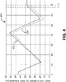
- FIGS. 4 to 6 there are shown graphs 400,500,600 comparing SOC determined using conventional coulomb counting vs. using the method 300 of FIG. 3 , with the measurement covariance equaling (10/3)*(pack current magnitude) and with both the measurement covariance and SEV i filtered using an IIR filter prior to being used in the Kalman filter.
- the battery pack comprises a 12s2p configuration of cells 106 for a total of twenty-four cells 106, and undergoes two partial charge and discharge cycles.
- FIG. 4 includes a graph 400 comprising a Kalman curve 402 generated using the method 300 of FIG. 3 and a coulomb counting curve 404 generated using conventional coulomb counting. As the graph 400 shows, while the Kalman and coulomb counting curves 402,404 are similar for the first discharge and part of the first charge cycle, they subsequently diverge with the Kalman curve 402 determining a higher SOC than the coulomb counting curve 404.
- the graph 500 of FIG. 5 is similar to the graph 400 of FIG. 4 except it is over four charge/discharge cycles, with a Kalman curve 502 generated using the method 300 of FIG. 3 and a coulomb counting curve 504 generated using conventional coulomb counting. Charging is done at 100 A and discharging is done at 200 A, and values of R k , M(SOC k,(-) ), u 1,2 , w k , v k (I), and C n are as described above in respect of FIG. 2 . As in FIG. 4 , the Kalman curve 502 generally determines a higher SOC for the battery pack than the coulomb counting curve 504, although this changes as the battery pack experiences more charge/discharge cycles.
- the coulomb counting curve 504 shows a higher SOC than the Kalman curve 502.
- the battery pack is then open circuited and after a short relaxation period the SOC is determined from an OCV reading at time t 2 .
- the SOC shown by Kalman curve 502 is within 0.3% of the SOC determined using an OCV reading, while the SOC shown by the coulomb counting curve is approximately 1% higher than the SOC determined using the OCV reading.
- the graph 600 of FIG. 6 also includes a Kalman curve 602 and a coulomb counting curve 604 analogous to the Kalman curves 402,502 and coulomb counting curves 504,604 of FIGS. 4 and 5 , respectively.
- Charging and discharging are done at 100 A and values of R k , M(SOC k,(-) ), u 1,2 , w k , v k (I), and C n are as described above in respect of FIG. 2 .
- the battery pack begins at approximately 60% SOC, it is then discharged to approximately 20% SOC, and then charged back up to approximately 60% SOC. As in FIGS.
- charging and discharging are done until time t 1 at which point the battery pack is open circuited, the battery pack relaxes for a short period, and the OCV of the battery pack is taken and the SOC is determined using this OCV.
- the Kalman curve 602 is significantly nearer to the SOC determined using the OCV at time t 2 than the coulomb counting curve 604.
- the graph 600 of FIG. 6 also comprises three additional curves: a weakest cell SEV curve 606, which is the measured SEV of the weakest cell 106 in the battery pack; a lowest SEV curve 608, which is the lowest, unfiltered SEV of any of the cells 106 in the battery pack; and a filtered SEV curve 610, which is the output of block 318 in FIG. 3 ( i.e., SEV KALMAN_INPUT after it has been filtered using the IIR filter described in respect of block 318 above).
- the graph 600 shows that the filtered SEV curve 610 has a mean that is similar to the mean of the weakest cell SEV curve 606, indicating that it generally represents the SEV of the weakest cell 106 in the battery pack except with reduced noise.
- the lowest SEV curve 608 is consistently approximately 40 mV lower than the filtered SEV curve 610, and if relied upon to determine SOC would result in the controller 102 determining the battery pack's SOC to be lower than it actually was; in this example embodiment, an error of approximately 10% in SOC could result from relying on the lowest SEV curve 608 to determine SOC as opposed to the filtered SEV curve 610.
- the controller 102 used in the foregoing embodiments may be, for example, a processing unit (such as a processor, microprocessor, or programmable logic controller) communicatively coupled to a non-transitory computer readable medium having stored on it program code for execution by the processing unit.
- the controller 102 may comprise a microcontroller (which comprises both a processing unit and a non-transitory computer readable medium), field programmable gate array (FPGA), or an application-specific integrated circuit (ASIC).
- a processing unit such as a processor, microprocessor, or programmable logic controller
- the controller 102 may comprise a microcontroller (which comprises both a processing unit and a non-transitory computer readable medium), field programmable gate array (FPGA), or an application-specific integrated circuit (ASIC).
- FPGA field programmable gate array
- ASIC application-specific integrated circuit
- Examples of computer readable media are non-transitory and include disc-based media such as CD-ROMs and DVDs, magnetic media such as hard drives and other forms of magnetic disk storage, semiconductor based media such as flash media, random access memory (including DRAM and SRAM), and read only memory.
- disc-based media such as CD-ROMs and DVDs
- magnetic media such as hard drives and other forms of magnetic disk storage
- semiconductor based media such as flash media
- random access memory including DRAM and SRAM
- read only memory read only memory
- FIGS. 2 and 3 are flowcharts of example methods. Some of the blocks illustrated in the flowcharts may be performed in an order other than that which is described. Also, it should be appreciated that not all of the blocks described in the flowcharts are required to be performed, that additional blocks may be added, and that some of the illustrated blocks may be substituted with other blocks.
Landscapes
- Physics & Mathematics (AREA)
- General Physics & Mathematics (AREA)
- Secondary Cells (AREA)
Applications Claiming Priority (1)
| Application Number | Priority Date | Filing Date | Title |
|---|---|---|---|
| US201562103375P | 2015-01-14 | 2015-01-14 |
Publications (2)
| Publication Number | Publication Date |
|---|---|
| EP3045925A1 true EP3045925A1 (fr) | 2016-07-20 |
| EP3045925B1 EP3045925B1 (fr) | 2023-03-01 |
Family
ID=55182213
Family Applications (1)
| Application Number | Title | Priority Date | Filing Date |
|---|---|---|---|
| EP16151330.4A Active EP3045925B1 (fr) | 2015-01-14 | 2016-01-14 | Procédé et système pour déterminer un état de charge de manière itérative d'une cellule de batterie |
Country Status (6)
| Country | Link |
|---|---|
| US (1) | US10422834B2 (fr) |
| EP (1) | EP3045925B1 (fr) |
| DK (1) | DK3045925T3 (fr) |
| ES (1) | ES2945600T3 (fr) |
| FI (1) | FI3045925T3 (fr) |
| PL (1) | PL3045925T3 (fr) |
Cited By (4)
| Publication number | Priority date | Publication date | Assignee | Title |
|---|---|---|---|---|
| CN109239608A (zh) * | 2018-08-10 | 2019-01-18 | 安徽力高新能源技术有限公司 | 一种实时修正锂电池soc-ocv曲线的方法 |
| EP3828565A1 (fr) * | 2019-11-26 | 2021-06-02 | Hyundai Motor Company | Véhicule et son procédé de commande |
| WO2021168836A1 (fr) * | 2020-02-28 | 2021-09-02 | 华为技术有限公司 | Procédé et dispositif de détection d'anomalie |
| WO2024126909A1 (fr) * | 2022-12-16 | 2024-06-20 | Stellantis Auto Sas | Estimation fiable de l'état de charge d'une batterie cellulaire d'un véhicule |
Families Citing this family (14)
| Publication number | Priority date | Publication date | Assignee | Title |
|---|---|---|---|---|
| CA3043117A1 (fr) * | 2016-11-07 | 2018-05-11 | Corvus Energy Inc. | Equilibrage d'une batterie a cellules multiples |
| US10654337B2 (en) | 2016-12-21 | 2020-05-19 | Thermo King Corporation | Methods and systems for automatic control of an accessory powered by an auxiliary power unit |
| KR102066702B1 (ko) * | 2017-01-02 | 2020-03-02 | 주식회사 엘지화학 | 배터리 관리 장치 및 이를 이용한 soc 캘리브레이션 방법 |
| US10566811B2 (en) * | 2017-01-11 | 2020-02-18 | Samsung Electronics Co., Ltd. | Method and apparatus estimating and controlling battery state |
| US20190190091A1 (en) * | 2017-12-18 | 2019-06-20 | Samsung Electronics Co., Ltd. | Method and apparatus estimating a state of battery |
| US10933825B2 (en) | 2017-12-28 | 2021-03-02 | Thermo King Corporation | Operation of vehicle accessories based on predicted runtime of a primary system |
| CN109655749B (zh) * | 2018-11-20 | 2021-03-09 | 惠州拓邦电气技术有限公司 | 采集数据矩阵智能跟踪校准方法及装置 |
| US20210349155A1 (en) | 2020-05-07 | 2021-11-11 | Zitara Technologies, Inc. | Battery analysis system and method |
| EP4413386A4 (fr) | 2021-10-04 | 2025-08-06 | Zitara Tech Inc | Système et procédé de gestion de batterie |
| KR20240121276A (ko) | 2021-12-09 | 2024-08-08 | 지타라 테크놀로지스, 인크. | 배터리 상태를 결정하기 위한 시스템 및 방법 |
| DE102022113179A1 (de) * | 2022-05-25 | 2023-11-30 | Webasto SE | Verfahren und System zum Betreiben eines Energiespeichers mit einer Mehrzahl von Batteriezellen |
| CN115166536B (zh) | 2022-09-01 | 2022-12-13 | 中创新航科技股份有限公司 | 一种电池系统的soc的确定方法及装置 |
| US12493078B2 (en) | 2023-10-11 | 2025-12-09 | Zitara Technologies, Inc. | System and method for degradation based battery control |
| US12528383B2 (en) * | 2024-01-29 | 2026-01-20 | Fca Us Llc | Kalman filter initialization control strategy |
Citations (8)
| Publication number | Priority date | Publication date | Assignee | Title |
|---|---|---|---|---|
| US6534954B1 (en) * | 2002-01-10 | 2003-03-18 | Compact Power Inc. | Method and apparatus for a battery state of charge estimator |
| DE102004046621A1 (de) * | 2003-09-30 | 2005-04-28 | Bosch Gmbh Robert | Vorrichtung oder Verfahren zur Signalverarbeitung |
| EP1873542A1 (fr) * | 2006-06-26 | 2008-01-02 | Samsung SDI Co., Ltd. | Appareil et méthode pour évaluer l'état de charge d'une pile |
| US20090037125A1 (en) * | 2005-11-10 | 2009-02-05 | Lg Chem, Ltd. | System, method, and article of manufacture for determining an estimated battery state vector |
| EP2233938A2 (fr) * | 2008-01-11 | 2010-09-29 | SK Energy Co., Ltd. | Procédé et dispositif de l'état de charge (soc) d'une batterie dans un système de gestion de batterie |
| GB2478557A (en) * | 2010-03-09 | 2011-09-14 | Ricardo Uk Ltd | Calculating battery state of charge using two or more different methods |
| US20120310568A1 (en) * | 2010-04-22 | 2012-12-06 | Enerdel, Inc. | Monitoring Battery State of Charge |
| US20140244193A1 (en) * | 2013-02-24 | 2014-08-28 | Fairchild Semiconductor Corporation | Battery state of charge tracking, equivalent circuit selection and benchmarking |
Family Cites Families (18)
| Publication number | Priority date | Publication date | Assignee | Title |
|---|---|---|---|---|
| AT331357B (de) | 1974-01-11 | 1976-08-25 | Jungfer Akkumulatoren | Elektrische anzeigevorrichtung fur den ladezustand einer sekundarbatterie |
| JPS5628476A (en) | 1979-08-14 | 1981-03-20 | Shin Kobe Electric Mach Co Ltd | Remained capacity meter for storage battery |
| US6359419B1 (en) | 2000-12-27 | 2002-03-19 | General Motors Corporation | Quasi-adaptive method for determining a battery's state of charge |
| US6845332B2 (en) | 2001-11-16 | 2005-01-18 | Toyota Jidosha Kabushiki Kaisha | State of charge calculation device and state of charge calculation method |
| US6789026B2 (en) * | 2002-12-29 | 2004-09-07 | Texas Instruments Incorporated | Circuit and method for monitoring battery state of charge |
| US6832171B2 (en) * | 2002-12-29 | 2004-12-14 | Texas Instruments Incorporated | Circuit and method for determining battery impedance increase with aging |
| US7321220B2 (en) | 2003-11-20 | 2008-01-22 | Lg Chem, Ltd. | Method for calculating power capability of battery packs using advanced cell model predictive techniques |
| JP4583765B2 (ja) | 2004-01-14 | 2010-11-17 | 富士重工業株式会社 | 蓄電デバイスの残存容量演算装置 |
| US7994755B2 (en) | 2008-01-30 | 2011-08-09 | Lg Chem, Ltd. | System, method, and article of manufacture for determining an estimated battery cell module state |
| FR2943794B1 (fr) | 2009-03-24 | 2011-05-06 | Saft Groupe Sa | Procede de determination de l'etat de sante d'une batterie |
| US8207706B2 (en) | 2009-08-04 | 2012-06-26 | Honda Motor Co., Ltd. | Method of estimating battery state of charge |
| US8635037B2 (en) | 2009-10-19 | 2014-01-21 | Nuvera Fuel Cells, Inc. | Battery state-of-charge management method |
| US8441262B2 (en) * | 2010-10-29 | 2013-05-14 | GM Global Technology Operations LLC | Optimization of electrical component parameters in energy storage system models |
| DE102011017113B4 (de) | 2011-04-14 | 2017-11-09 | Iav Gmbh Ingenieurgesellschaft Auto Und Verkehr | Verfahren zur Bestimmung von Zustandsgrößen eines Akkumulators |
| US9869725B2 (en) | 2012-05-16 | 2018-01-16 | Robert Bosch Gmbh | Battery system and method with capacity estimator |
| US9575128B2 (en) * | 2013-03-12 | 2017-02-21 | GM Global Technology Operations LLC | Battery state-of-charge estimation for hybrid and electric vehicles using extended kalman filter techniques |
| US20140266228A1 (en) * | 2013-03-15 | 2014-09-18 | Qualcomm Incorporated | Active measurement of battery equivalent series resistance |
| US9927492B2 (en) * | 2013-05-29 | 2018-03-27 | Nxp Usa, Inc. | Cell monitoring apparatus, battery monitoring apparatus, integrated circuit and method of monitoring a rechargeable cell |
-
2016
- 2016-01-14 PL PL16151330.4T patent/PL3045925T3/pl unknown
- 2016-01-14 EP EP16151330.4A patent/EP3045925B1/fr active Active
- 2016-01-14 FI FIEP16151330.4T patent/FI3045925T3/fi active
- 2016-01-14 DK DK16151330.4T patent/DK3045925T3/da active
- 2016-01-14 US US14/995,898 patent/US10422834B2/en active Active
- 2016-01-14 ES ES16151330T patent/ES2945600T3/es active Active
Patent Citations (8)
| Publication number | Priority date | Publication date | Assignee | Title |
|---|---|---|---|---|
| US6534954B1 (en) * | 2002-01-10 | 2003-03-18 | Compact Power Inc. | Method and apparatus for a battery state of charge estimator |
| DE102004046621A1 (de) * | 2003-09-30 | 2005-04-28 | Bosch Gmbh Robert | Vorrichtung oder Verfahren zur Signalverarbeitung |
| US20090037125A1 (en) * | 2005-11-10 | 2009-02-05 | Lg Chem, Ltd. | System, method, and article of manufacture for determining an estimated battery state vector |
| EP1873542A1 (fr) * | 2006-06-26 | 2008-01-02 | Samsung SDI Co., Ltd. | Appareil et méthode pour évaluer l'état de charge d'une pile |
| EP2233938A2 (fr) * | 2008-01-11 | 2010-09-29 | SK Energy Co., Ltd. | Procédé et dispositif de l'état de charge (soc) d'une batterie dans un système de gestion de batterie |
| GB2478557A (en) * | 2010-03-09 | 2011-09-14 | Ricardo Uk Ltd | Calculating battery state of charge using two or more different methods |
| US20120310568A1 (en) * | 2010-04-22 | 2012-12-06 | Enerdel, Inc. | Monitoring Battery State of Charge |
| US20140244193A1 (en) * | 2013-02-24 | 2014-08-28 | Fairchild Semiconductor Corporation | Battery state of charge tracking, equivalent circuit selection and benchmarking |
Cited By (10)
| Publication number | Priority date | Publication date | Assignee | Title |
|---|---|---|---|---|
| CN109239608A (zh) * | 2018-08-10 | 2019-01-18 | 安徽力高新能源技术有限公司 | 一种实时修正锂电池soc-ocv曲线的方法 |
| CN109239608B (zh) * | 2018-08-10 | 2021-01-19 | 力高(山东)新能源技术有限公司 | 一种实时修正锂电池soc-ocv曲线的方法 |
| EP3828565A1 (fr) * | 2019-11-26 | 2021-06-02 | Hyundai Motor Company | Véhicule et son procédé de commande |
| KR20210064770A (ko) * | 2019-11-26 | 2021-06-03 | 현대자동차주식회사 | 차량 및 차량의 제어 방법 |
| CN112937365A (zh) * | 2019-11-26 | 2021-06-11 | 现代自动车株式会社 | 车辆及其控制方法 |
| US11505088B2 (en) | 2019-11-26 | 2022-11-22 | Hyundai Motor Company | Vehicle and control method thereof |
| CN112937365B (zh) * | 2019-11-26 | 2025-09-30 | 现代自动车株式会社 | 车辆及其控制方法 |
| WO2021168836A1 (fr) * | 2020-02-28 | 2021-09-02 | 华为技术有限公司 | Procédé et dispositif de détection d'anomalie |
| WO2024126909A1 (fr) * | 2022-12-16 | 2024-06-20 | Stellantis Auto Sas | Estimation fiable de l'état de charge d'une batterie cellulaire d'un véhicule |
| FR3143764A1 (fr) * | 2022-12-16 | 2024-06-21 | Psa Automobiles Sa | Estimation fiable de l’état de charge d’une batterie cellulaire d’un véhicule |
Also Published As
| Publication number | Publication date |
|---|---|
| FI3045925T3 (fi) | 2023-05-29 |
| ES2945600T3 (es) | 2023-07-04 |
| PL3045925T3 (pl) | 2023-08-07 |
| US10422834B2 (en) | 2019-09-24 |
| EP3045925B1 (fr) | 2023-03-01 |
| US20160202325A1 (en) | 2016-07-14 |
| DK3045925T3 (da) | 2023-06-06 |
Similar Documents
| Publication | Publication Date | Title |
|---|---|---|
| EP3045925B1 (fr) | Procédé et système pour déterminer un état de charge de manière itérative d'une cellule de batterie | |
| CN107110915B (zh) | 电池组的电池单元的充电状态的自动估计方法 | |
| JP7292404B2 (ja) | バッテリ健全状態の推定方法 | |
| CN110914696B (zh) | 用于在电池的操作期间估计电池开路池格电压、充电状态以及健康状态的方法和系统 | |
| US9709635B2 (en) | System and method for SOC estimation of a battery | |
| US20190170826A1 (en) | Battery state-of-health determination upon charging | |
| CN1835273B (zh) | 电源装置、其用状态检测装置及其中用初始特性提取装置 | |
| EP2615468B1 (fr) | Dispositif d'estimation de paramètres | |
| US10267863B2 (en) | Automatic method for determining the state-of-charge of a battery | |
| CN107110916B (zh) | 电池组的电池单元的充电状态的自动估计方法 | |
| US9267997B2 (en) | Systems and methods to determine the condition of a battery | |
| JP6369340B2 (ja) | 蓄電装置および蓄電装置の制御方法 | |
| CN114114038A (zh) | 一种全寿命全温度下锂电池soc及可用容量联合估计方法 | |
| CN113853524B (zh) | 用于估计电池状态的方法 | |
| CN107942261B (zh) | 电池荷电状态的估计方法及系统 | |
| KR20220034543A (ko) | 배터리의 충전상태를 추정하는 방법 | |
| JP2021533338A (ja) | バッテリー管理システム、バッテリー管理方法、バッテリーパック及び電気車両 | |
| US20150226807A1 (en) | Determination of nominal cell resistance for real-time estimation of state-of-charge in lithium batteries | |
| US20180321324A1 (en) | Voltage based zero configuration battery management | |
| KR20170092589A (ko) | 배터리의 셀의 충전의 상태를 추정하는 자동적 방법 | |
| CN107438771A (zh) | 电池参数的估计 | |
| CN107894570B (zh) | 基于Thevenin模型的电池组SOC的估算方法和装置 | |
| KR20120046355A (ko) | 배터리의 교환 시기 통보 장치 및 방법 | |
| US20190229539A1 (en) | Power storage apparatus | |
| CN104833917B (zh) | 用于锂蓄电池中荷电状态实时估算的标称电池电阻的确定 |
Legal Events
| Date | Code | Title | Description |
|---|---|---|---|
| PUAI | Public reference made under article 153(3) epc to a published international application that has entered the european phase |
Free format text: ORIGINAL CODE: 0009012 |
|
| AK | Designated contracting states |
Kind code of ref document: A1 Designated state(s): AL AT BE BG CH CY CZ DE DK EE ES FI FR GB GR HR HU IE IS IT LI LT LU LV MC MK MT NL NO PL PT RO RS SE SI SK SM TR |
|
| AX | Request for extension of the european patent |
Extension state: BA ME |
|
| STAA | Information on the status of an ep patent application or granted ep patent |
Free format text: STATUS: REQUEST FOR EXAMINATION WAS MADE |
|
| 17P | Request for examination filed |
Effective date: 20170116 |
|
| RBV | Designated contracting states (corrected) |
Designated state(s): AL AT BE BG CH CY CZ DE DK EE ES FI FR GB GR HR HU IE IS IT LI LT LU LV MC MK MT NL NO PL PT RO RS SE SI SK SM TR |
|
| R17P | Request for examination filed (corrected) |
Effective date: 20170116 |
|
| REG | Reference to a national code |
Ref country code: DE Ref legal event code: R079 Ref document number: 602016078025 Country of ref document: DE Free format text: PREVIOUS MAIN CLASS: G01R0031360000 Ipc: G01R0031367000 |
|
| GRAP | Despatch of communication of intention to grant a patent |
Free format text: ORIGINAL CODE: EPIDOSNIGR1 |
|
| STAA | Information on the status of an ep patent application or granted ep patent |
Free format text: STATUS: GRANT OF PATENT IS INTENDED |
|
| RIC1 | Information provided on ipc code assigned before grant |
Ipc: G01R 31/396 20190101ALI20220907BHEP Ipc: G01R 31/3842 20190101ALI20220907BHEP Ipc: G01R 31/367 20190101AFI20220907BHEP |
|
| INTG | Intention to grant announced |
Effective date: 20220929 |
|
| GRAS | Grant fee paid |
Free format text: ORIGINAL CODE: EPIDOSNIGR3 |
|
| GRAA | (expected) grant |
Free format text: ORIGINAL CODE: 0009210 |
|
| STAA | Information on the status of an ep patent application or granted ep patent |
Free format text: STATUS: THE PATENT HAS BEEN GRANTED |
|
| AK | Designated contracting states |
Kind code of ref document: B1 Designated state(s): AL AT BE BG CH CY CZ DE DK EE ES FI FR GB GR HR HU IE IS IT LI LT LU LV MC MK MT NL NO PL PT RO RS SE SI SK SM TR |
|
| REG | Reference to a national code |
Ref country code: GB Ref legal event code: FG4D |
|
| REG | Reference to a national code |
Ref country code: CH Ref legal event code: EP Ref country code: AT Ref legal event code: REF Ref document number: 1551349 Country of ref document: AT Kind code of ref document: T Effective date: 20230315 |
|
| REG | Reference to a national code |
Ref country code: DE Ref legal event code: R096 Ref document number: 602016078025 Country of ref document: DE |
|
| REG | Reference to a national code |
Ref country code: IE Ref legal event code: FG4D |
|
| REG | Reference to a national code |
Ref country code: SE Ref legal event code: TRGR |
|
| REG | Reference to a national code |
Ref country code: NO Ref legal event code: T2 Effective date: 20230301 |
|
| REG | Reference to a national code |
Ref country code: DK Ref legal event code: T3 Effective date: 20230531 |
|
| REG | Reference to a national code |
Ref country code: NL Ref legal event code: FP |
|
| REG | Reference to a national code |
Ref country code: LT Ref legal event code: MG9D |
|
| REG | Reference to a national code |
Ref country code: ES Ref legal event code: FG2A Ref document number: 2945600 Country of ref document: ES Kind code of ref document: T3 Effective date: 20230704 |
|
| REG | Reference to a national code |
Ref country code: GR Ref legal event code: EP Ref document number: 20230400796 Country of ref document: GR Effective date: 20230710 |
|
| PG25 | Lapsed in a contracting state [announced via postgrant information from national office to epo] |
Ref country code: RS Free format text: LAPSE BECAUSE OF FAILURE TO SUBMIT A TRANSLATION OF THE DESCRIPTION OR TO PAY THE FEE WITHIN THE PRESCRIBED TIME-LIMIT Effective date: 20230301 Ref country code: LV Free format text: LAPSE BECAUSE OF FAILURE TO SUBMIT A TRANSLATION OF THE DESCRIPTION OR TO PAY THE FEE WITHIN THE PRESCRIBED TIME-LIMIT Effective date: 20230301 Ref country code: LT Free format text: LAPSE BECAUSE OF FAILURE TO SUBMIT A TRANSLATION OF THE DESCRIPTION OR TO PAY THE FEE WITHIN THE PRESCRIBED TIME-LIMIT Effective date: 20230301 Ref country code: HR Free format text: LAPSE BECAUSE OF FAILURE TO SUBMIT A TRANSLATION OF THE DESCRIPTION OR TO PAY THE FEE WITHIN THE PRESCRIBED TIME-LIMIT Effective date: 20230301 |
|
| REG | Reference to a national code |
Ref country code: AT Ref legal event code: MK05 Ref document number: 1551349 Country of ref document: AT Kind code of ref document: T Effective date: 20230301 |
|
| PG25 | Lapsed in a contracting state [announced via postgrant information from national office to epo] |
Ref country code: SM Free format text: LAPSE BECAUSE OF FAILURE TO SUBMIT A TRANSLATION OF THE DESCRIPTION OR TO PAY THE FEE WITHIN THE PRESCRIBED TIME-LIMIT Effective date: 20230301 Ref country code: RO Free format text: LAPSE BECAUSE OF FAILURE TO SUBMIT A TRANSLATION OF THE DESCRIPTION OR TO PAY THE FEE WITHIN THE PRESCRIBED TIME-LIMIT Effective date: 20230301 Ref country code: PT Free format text: LAPSE BECAUSE OF FAILURE TO SUBMIT A TRANSLATION OF THE DESCRIPTION OR TO PAY THE FEE WITHIN THE PRESCRIBED TIME-LIMIT Effective date: 20230703 Ref country code: EE Free format text: LAPSE BECAUSE OF FAILURE TO SUBMIT A TRANSLATION OF THE DESCRIPTION OR TO PAY THE FEE WITHIN THE PRESCRIBED TIME-LIMIT Effective date: 20230301 Ref country code: CZ Free format text: LAPSE BECAUSE OF FAILURE TO SUBMIT A TRANSLATION OF THE DESCRIPTION OR TO PAY THE FEE WITHIN THE PRESCRIBED TIME-LIMIT Effective date: 20230301 Ref country code: AT Free format text: LAPSE BECAUSE OF FAILURE TO SUBMIT A TRANSLATION OF THE DESCRIPTION OR TO PAY THE FEE WITHIN THE PRESCRIBED TIME-LIMIT Effective date: 20230301 |
|
| PG25 | Lapsed in a contracting state [announced via postgrant information from national office to epo] |
Ref country code: SK Free format text: LAPSE BECAUSE OF FAILURE TO SUBMIT A TRANSLATION OF THE DESCRIPTION OR TO PAY THE FEE WITHIN THE PRESCRIBED TIME-LIMIT Effective date: 20230301 Ref country code: IS Free format text: LAPSE BECAUSE OF FAILURE TO SUBMIT A TRANSLATION OF THE DESCRIPTION OR TO PAY THE FEE WITHIN THE PRESCRIBED TIME-LIMIT Effective date: 20230701 |
|
| REG | Reference to a national code |
Ref country code: DE Ref legal event code: R097 Ref document number: 602016078025 Country of ref document: DE |
|
| PLBE | No opposition filed within time limit |
Free format text: ORIGINAL CODE: 0009261 |
|
| STAA | Information on the status of an ep patent application or granted ep patent |
Free format text: STATUS: NO OPPOSITION FILED WITHIN TIME LIMIT |
|
| PG25 | Lapsed in a contracting state [announced via postgrant information from national office to epo] |
Ref country code: SI Free format text: LAPSE BECAUSE OF FAILURE TO SUBMIT A TRANSLATION OF THE DESCRIPTION OR TO PAY THE FEE WITHIN THE PRESCRIBED TIME-LIMIT Effective date: 20230301 |
|
| 26N | No opposition filed |
Effective date: 20231204 |
|
| PG25 | Lapsed in a contracting state [announced via postgrant information from national office to epo] |
Ref country code: MC Free format text: LAPSE BECAUSE OF FAILURE TO SUBMIT A TRANSLATION OF THE DESCRIPTION OR TO PAY THE FEE WITHIN THE PRESCRIBED TIME-LIMIT Effective date: 20230301 |
|
| PG25 | Lapsed in a contracting state [announced via postgrant information from national office to epo] |
Ref country code: MC Free format text: LAPSE BECAUSE OF FAILURE TO SUBMIT A TRANSLATION OF THE DESCRIPTION OR TO PAY THE FEE WITHIN THE PRESCRIBED TIME-LIMIT Effective date: 20230301 |
|
| REG | Reference to a national code |
Ref country code: CH Ref legal event code: PL |
|
| PG25 | Lapsed in a contracting state [announced via postgrant information from national office to epo] |
Ref country code: LU Free format text: LAPSE BECAUSE OF NON-PAYMENT OF DUE FEES Effective date: 20240114 |
|
| PG25 | Lapsed in a contracting state [announced via postgrant information from national office to epo] |
Ref country code: LU Free format text: LAPSE BECAUSE OF NON-PAYMENT OF DUE FEES Effective date: 20240114 |
|
| PG25 | Lapsed in a contracting state [announced via postgrant information from national office to epo] |
Ref country code: BE Free format text: LAPSE BECAUSE OF NON-PAYMENT OF DUE FEES Effective date: 20240131 |
|
| PG25 | Lapsed in a contracting state [announced via postgrant information from national office to epo] |
Ref country code: CH Free format text: LAPSE BECAUSE OF NON-PAYMENT OF DUE FEES Effective date: 20240131 |
|
| PG25 | Lapsed in a contracting state [announced via postgrant information from national office to epo] |
Ref country code: CH Free format text: LAPSE BECAUSE OF NON-PAYMENT OF DUE FEES Effective date: 20240131 Ref country code: BE Free format text: LAPSE BECAUSE OF NON-PAYMENT OF DUE FEES Effective date: 20240131 |
|
| REG | Reference to a national code |
Ref country code: BE Ref legal event code: MM Effective date: 20240131 |
|
| PG25 | Lapsed in a contracting state [announced via postgrant information from national office to epo] |
Ref country code: BG Free format text: LAPSE BECAUSE OF FAILURE TO SUBMIT A TRANSLATION OF THE DESCRIPTION OR TO PAY THE FEE WITHIN THE PRESCRIBED TIME-LIMIT Effective date: 20230301 |
|
| PG25 | Lapsed in a contracting state [announced via postgrant information from national office to epo] |
Ref country code: BG Free format text: LAPSE BECAUSE OF FAILURE TO SUBMIT A TRANSLATION OF THE DESCRIPTION OR TO PAY THE FEE WITHIN THE PRESCRIBED TIME-LIMIT Effective date: 20230301 |
|
| PGFP | Annual fee paid to national office [announced via postgrant information from national office to epo] |
Ref country code: PL Payment date: 20241223 Year of fee payment: 10 Ref country code: GR Payment date: 20241220 Year of fee payment: 10 |
|
| PG25 | Lapsed in a contracting state [announced via postgrant information from national office to epo] |
Ref country code: IE Free format text: LAPSE BECAUSE OF NON-PAYMENT OF DUE FEES Effective date: 20240114 |
|
| PG25 | Lapsed in a contracting state [announced via postgrant information from national office to epo] |
Ref country code: IE Free format text: LAPSE BECAUSE OF NON-PAYMENT OF DUE FEES Effective date: 20240114 |
|
| PG25 | Lapsed in a contracting state [announced via postgrant information from national office to epo] |
Ref country code: CY Free format text: LAPSE BECAUSE OF FAILURE TO SUBMIT A TRANSLATION OF THE DESCRIPTION OR TO PAY THE FEE WITHIN THE PRESCRIBED TIME-LIMIT; INVALID AB INITIO Effective date: 20160114 |
|
| PG25 | Lapsed in a contracting state [announced via postgrant information from national office to epo] |
Ref country code: HU Free format text: LAPSE BECAUSE OF FAILURE TO SUBMIT A TRANSLATION OF THE DESCRIPTION OR TO PAY THE FEE WITHIN THE PRESCRIBED TIME-LIMIT; INVALID AB INITIO Effective date: 20160114 |
|
| PGFP | Annual fee paid to national office [announced via postgrant information from national office to epo] |
Ref country code: GB Payment date: 20251210 Year of fee payment: 11 |
|
| PGFP | Annual fee paid to national office [announced via postgrant information from national office to epo] |
Ref country code: NO Payment date: 20251112 Year of fee payment: 11 |
|
| PGFP | Annual fee paid to national office [announced via postgrant information from national office to epo] |
Ref country code: FI Payment date: 20251209 Year of fee payment: 11 Ref country code: DK Payment date: 20251209 Year of fee payment: 11 |
|
| PGFP | Annual fee paid to national office [announced via postgrant information from national office to epo] |
Ref country code: NL Payment date: 20251210 Year of fee payment: 11 Ref country code: FR Payment date: 20251210 Year of fee payment: 11 |
|
| PGFP | Annual fee paid to national office [announced via postgrant information from national office to epo] |
Ref country code: SE Payment date: 20251212 Year of fee payment: 11 |
|
| PGFP | Annual fee paid to national office [announced via postgrant information from national office to epo] |
Ref country code: ES Payment date: 20260220 Year of fee payment: 11 |
|
| PGFP | Annual fee paid to national office [announced via postgrant information from national office to epo] |
Ref country code: DE Payment date: 20251209 Year of fee payment: 11 |
|
| PGFP | Annual fee paid to national office [announced via postgrant information from national office to epo] |
Ref country code: IT Payment date: 20251201 Year of fee payment: 11 |
|
| PGFP | Annual fee paid to national office [announced via postgrant information from national office to epo] |
Ref country code: TR Payment date: 20260112 Year of fee payment: 11 |