EP1873770A1 - Dispositif de détection optique - Google Patents
Dispositif de détection optique Download PDFInfo
- Publication number
- EP1873770A1 EP1873770A1 EP06732338A EP06732338A EP1873770A1 EP 1873770 A1 EP1873770 A1 EP 1873770A1 EP 06732338 A EP06732338 A EP 06732338A EP 06732338 A EP06732338 A EP 06732338A EP 1873770 A1 EP1873770 A1 EP 1873770A1
- Authority
- EP
- European Patent Office
- Prior art keywords
- light beam
- phase correcting
- light
- objective lens
- phase
- Prior art date
- Legal status (The legal status is an assumption and is not a legal conclusion. Google has not performed a legal analysis and makes no representation as to the accuracy of the status listed.)
- Granted
Links
Images








Classifications
-
- G—PHYSICS
- G11—INFORMATION STORAGE
- G11B—INFORMATION STORAGE BASED ON RELATIVE MOVEMENT BETWEEN RECORD CARRIER AND TRANSDUCER
- G11B7/00—Recording or reproducing by optical means, e.g. recording using a thermal beam of optical radiation by modifying optical properties or the physical structure, reproducing using an optical beam at lower power by sensing optical properties; Record carriers therefor
- G11B7/12—Heads, e.g. forming of the optical beam spot or modulation of the optical beam
- G11B7/135—Means for guiding the beam from the source to the record carrier or from the record carrier to the detector
- G11B7/1353—Diffractive elements, e.g. holograms or gratings
-
- G—PHYSICS
- G11—INFORMATION STORAGE
- G11B—INFORMATION STORAGE BASED ON RELATIVE MOVEMENT BETWEEN RECORD CARRIER AND TRANSDUCER
- G11B7/00—Recording or reproducing by optical means, e.g. recording using a thermal beam of optical radiation by modifying optical properties or the physical structure, reproducing using an optical beam at lower power by sensing optical properties; Record carriers therefor
- G11B7/12—Heads, e.g. forming of the optical beam spot or modulation of the optical beam
- G11B7/135—Means for guiding the beam from the source to the record carrier or from the record carrier to the detector
- G11B7/1365—Separate or integrated refractive elements, e.g. wave plates
- G11B7/1367—Stepped phase plates
-
- G—PHYSICS
- G11—INFORMATION STORAGE
- G11B—INFORMATION STORAGE BASED ON RELATIVE MOVEMENT BETWEEN RECORD CARRIER AND TRANSDUCER
- G11B7/00—Recording or reproducing by optical means, e.g. recording using a thermal beam of optical radiation by modifying optical properties or the physical structure, reproducing using an optical beam at lower power by sensing optical properties; Record carriers therefor
- G11B7/12—Heads, e.g. forming of the optical beam spot or modulation of the optical beam
- G11B7/135—Means for guiding the beam from the source to the record carrier or from the record carrier to the detector
- G11B7/1392—Means for controlling the beam wavefront, e.g. for correction of aberration
- G11B7/13922—Means for controlling the beam wavefront, e.g. for correction of aberration passive
-
- G—PHYSICS
- G11—INFORMATION STORAGE
- G11B—INFORMATION STORAGE BASED ON RELATIVE MOVEMENT BETWEEN RECORD CARRIER AND TRANSDUCER
- G11B7/00—Recording or reproducing by optical means, e.g. recording using a thermal beam of optical radiation by modifying optical properties or the physical structure, reproducing using an optical beam at lower power by sensing optical properties; Record carriers therefor
- G11B2007/0003—Recording, reproducing or erasing systems characterised by the structure or type of the carrier
- G11B2007/0006—Recording, reproducing or erasing systems characterised by the structure or type of the carrier adapted for scanning different types of carrier, e.g. CD & DVD
Definitions
- the present invention relates to an optical pickup device and, more particularly, to an optical pickup device which guides each of a plurality of light beams having wavelengths different from one another corresponding to a plurality of optical recording media having specifications different from one another to a common objective lens and focuses the light beams on an optical recording medium.
- CDs and DVDs digital versatile disks
- next generation DVDs also referred to as high-definition DVDs
- an optical pickup which records data on and/or plays back data from a next generation DVD is desired to adopt a compatible technology for enabling itself also to record data on and/or play back data from DVDs and CDs which are conventional optical recording media using a common objective lens.
- the optical recording media differ from one another in used wavelength, numerical aperture (NA), and the thickness of a signal plane protecting substrate, as shown in Table 1. Accordingly, if a common objective lens is used, spherical aberration cannot be corrected, and it is impossible to normally record or play back information.
- NA numerical aperture
- Table 1 Optical recording medium type Used wavelength (nm) NA Thickness of protecting substrate (mm) Next generation DVD 1 405 0.85 0.1 Next generation DVD 2 405 0.65 0.6 DVD 650 0.6 0.6 CD 780 0.45 1.2
- FIG. 1 shows an optical pickup which records information on and/or plays back information from a plurality of optical recording media having specifications different from one another using a phase correcting element in order to solve the above-described problem (see Japanese Patent Application Laid-Open No. 2004-246931 ).
- an objective lens 1 is designed such that the wave front aberration to light having a wavelength corresponding to a next generation DVD is minimum on the signal plane of an optical recording medium (next generation DVD) 2-1 when the light is incident as a parallel light beam.
- a DVD hologram module 3 and a CD hologram module 4, in each of which light receiving and emitting units are packaged, are used as DVD and CD light sources.
- a light beam radiated from a next generation DVD semiconductor laser 5 is transformed into a parallel light beam by a collimator lens 6, passes through a deflection beam splitter 7. and DVD and CD dichroic prisms 8 and 9 for light beam separation, and changes its direction 90° by a prism 10.
- a wavelength plate 11 changes the state of polarization of the light beam from linear polarization into circular polarization, and an aperture restriction element 12 restricts the diameter of the light beam to a light beam diameter corresponding to the NA of a next generation DVD.
- the light beam passes through a phase correcting element 13 without changing its parallel light beam state (with an equiphase wave surface kept planar), comes incident on the objective lens 1, and is focused on the signal plane of the optical recording medium (next generation DVD) 2-1, thereby recording and/or playing back information.
- a light beam reflected from the optical recording medium 2-1 is transformed into a circularly polarized light beam having an opposite rotational direction and is transformed into a parallel light beam by the objective lens 1.
- the wavelength plate 11 changes the state of polarization of the light beam from circular polarization into linear polarization such that the resultant linearly polarized light beam is orthogonal to the original linearly polarized light beam.
- the light beam changes its direction 90° by the prism 10, is reflected by the deflection beam splitter 7, and is focused on a light receiving element 15 by a detecting lens 14.
- a light beam radiated from the DVD hologram module 3 is transformed into a parallel light beam by a coupling lens 16, is reflected by the dichroic prism 8, passes through the dichroic prism 9, and changes its direction 90° by the prism 10.
- the wavelength plate 11 changes the state of polarization of the light beam from linear polarization into circular polarization, the aperture restriction element 12 restricts the diameter of the light beam to a light beam diameter corresponding to the NA of a DVD, and the phase correcting element 13 corrects the spherical aberration to the light beam.
- the light beam comes incident on the objective lens 1 and is focused on the signal plane of an optical recording medium (DVD) 2-2, thereby recording and/or playing back information.
- a light beam reflected from the optical recording medium 2-2, which is a DVD, is transformed into a circularly polarized light beam having an opposite rotational direction and is transformed into a parallel light beam by the objective lens 1 and phase correcting element 13.
- the wavelength plate 11 changes the state of polarization of the light beam from circular polarization into linear polarization such that the resultant linearly polarized light beam is orthogonal to the original linearly polarized light beam.
- the light beam changes its direction 90° by the prism 10, is reflected by the dichroic prism 8, and is focused on a light receiving element of the DVD hologram module 3 by the coupling lens 16.
- a light beam radiated from the CD hologram module 4 is transformed into a predetermined divergent light beam by a coupling lens 17, is reflected by the dichroic prism 9, and changes its direction 90° by the prism 10.
- the wavelength plate 11 changes the state of polarization from linear polarization into circular polarization, and the aperture restriction element 12 restricts the diameter of the light beam to a light beam diameter corresponding to the NA of a CD.
- the light beam passes through the phase correcting element 13 without changing the shape of an equiphase wave surface, comes incident on the objective lens 1, and is focused on the signal plane of an optical recording medium (CD) 2-3, thereby recording and/or playing back information.
- a light beam reflected from the optical recording medium 2-3 is transformed into a circularly polarized light beam having an opposite rotational direction and is transformed into a predetermined convergent light beam by the objective lens 1.
- the wavelength plate 11 changes the state of polarization of the light beam from circular polarization into linear polarization such that the resultant linearly polarized light beam is orthogonal to the original linearly polarized light beam.
- the light beam changes its direction 90° by the prism 10, is reflected by the dichroic prism 9, and is focused on a light receiving element of the CD hologram module 4 by the coupling lens 17.
- phase correcting element The process of giving phase shifts which are integer multiples of 2 ⁇ to light beams having wavelengths corresponding to a next generation DVD and CD which are not exactly integer multiples by the common phase correcting element and allowing the light beams to pass through the common phase correcting element without changing the shape of an equiphase wave surface limits the types of glasses available for use in the phase correcting element to specific ones. Accordingly, the flexibility in configuring the optical system becomes extremely lower, and designing of the optical system becomes difficult.
- the present invention has been made in consideration of the above-described conventional problems, and has as its object to provide an optical pickup device which enables prevention of exacerbation of spherical aberration during tracking of an objective lens without needing any finite optical system and securement of the flexibility in configuring an optical system.
- a first aspect of the present invention is an optical pickup device including k light emitting elements which radiate light beams having wavelengths different from one another corresponding to k optical recording media different from one another in specifications including a used wavelength, a numerical aperture (NA), and a thickness of a signal plane protecting substrate, a common objective lens which focuses the light beams radiated from the light emitting elements on the k optical recording media, which are interchangeably mounted at a predetermined location, and an optical system which transforms the light beams radiated from the light emitting elements into parallel light beams and guides the parallel light beams to the objective lens such that axes coincide with a light axis of the objective lens, characterized in that light beam restriction means and phase correcting means are located backward and forward between the optical system and the objective lens such that the phase correcting means are nearer the objective lens in relation to the light beam restriction means, the light beam restriction means propagate each of the k light beams having the different only at a portion wavelengths, and the phase correcting means correct phases of the k light
- a second aspect of the present invention is an optical pickup device including two light emitting elements which radiate light beams having wavelengths different from each other corresponding to two optical recording media different from each other in specifications including a used wavelength, a numerical aperture (NA), and a thickness of a signal plane protecting substrate, a common objective lens which focuses the light beams radiated from the light emitting elements on the two optical recording media, which are interchangeably mounted at a predetermined location, and an optical system which transforms the light beams radiated from the light emitting elements into parallel light beams and guides the parallel light beams to the objective lens such that axes coincide with a light axis of the objective lens, light beam diameters of ⁇ 1 and ⁇ 2 commensurate with the numerical apertures for the two optical recording media satisfying a relation ⁇ 1 > ⁇ 2, characterized in that of the two light beams, one having the light beam diameter of ⁇ 1 commensurate with the numerical aperture for the corresponding optical recording medium is referred to as a first light beam, and the other having the light
- An embodiment of the present invention is characterized in that the inner diameter of the first phase correcting zone is set to be approximately ⁇ 1 ⁇ 0.85.
- An embodiment of the present invention is characterized in that the inner diameter of ⁇ 3 of the second phase correcting zone is set to be approximately ⁇ 2 ⁇ 0.85.
- each phase correcting zone is formed using a diffraction optical region exhibiting a pseudo-kinoform shape having stepped structures with two or more steps in cross section.
- phase correcting means and light beam restriction means are integrated into one piece by forming the phase correcting means and light beam restriction means on two sides of a common substrate or bonding the phase correcting means and light beam restriction means together.
- An embodiment of the present invention is characterized in that a holding mechanism for the objective lens is caused to hold the phase correcting means together with the objective lens.
- An embodiment of the present invention is characterized in that a holding mechanism for the objective lens is caused to hold the light beam restriction means and phase correcting means together with the objective lens.
- a third aspect of the present invention is an optical pickup device including three light emitting elements which radiate light beams having wavelengths different from one another corresponding to three optical recording media different from one another in specifications including a used wavelength, a numerical aperture (NA), and a thickness of a signal plane protecting substrate, a common objective lens which focuses the light beams radiated from the light emitting elements on the three optical recording media, which are interchangeably mounted at a predetermined location, and an optical system which transforms the light beams radiated from the light emitting elements into parallel light beams and guides the parallel light beams to the objective lens such that axes coincide with a light axis of the objective lens, the objective lens being formed such that wave front aberration when a specific one of the light beams is focused on a corresponding specific one of the optical recording media is minimum, light beam diameters of ⁇ 0, ⁇ 1, and ⁇ 2 commensurate with the numerical apertures for the specific one optical recording medium and the other two optical recording media satisfying a relation ⁇ 0 > ⁇ 1 > ⁇
- An embodiment of the present invention is characterized in that the inner diameter of the first phase correcting zone is set to be approximately ⁇ 1 ⁇ 0.85.
- An embodiment of the present invention is characterized in that the inner diameter of ⁇ 3 of the second phase correcting zone is set to be approximately ⁇ 2 ⁇ 0.85.
- each phase correcting zone is formed using a diffraction optical region exhibiting a pseudo-kinoform shape having stepped structures with two or more steps in cross section.
- phase correcting means and light beam restriction means are integrated into one piece by forming the phase correcting means and light beam restriction means on two sides of a common substrate or bonding the phase correcting means and light beam restriction means together.
- An embodiment of the present invention is characterized in that a holding mechanism for the objective lens is caused to hold the phase correcting means together with the objective lens.
- An embodiment of the present invention is characterized in that a holding mechanism for the objective lens is caused to hold the light beam restriction means and phase correcting means together with the objective lens.
- a common objective lens and common phase correcting means make it possible to correct the spherical aberration to each of light beams having two or more wavelengths by a parallel light beam, prevent exacerbation of spherical aberration during tracking of the objective lens without needing any finite optical system, and secure the flexibility in configuring an optical system.
- an objective lens commonly used for three light beams having wavelengths different from one another is formed such that the wave front aberration to a specific one of the light beams as a parallel light beam is minimum on a corresponding optical recording medium, it is possible to correct the spherical aberration to each of the light beams except for the specific one light beam, the two light beams by common phase correcting means, prevent exacerbation of spherical aberration during tracking of the objective lens without needing any finite optical system, and secure the flexibility in configuring an optical system.
- phase correcting zone corresponding to a part whose diameter falls within the range of 1 ⁇ (where ⁇ is a diameter as the light beam diameter of a light beam to be phase-corrected) to approximately 0.85 ⁇ is provided in the phase correcting means.
- phase correcting zones are concentrically provided for each of the light beams to be phase-corrected. With this configuration, good point image light intensity distribution free of side lobes is achieved.
- Each phase correcting zone of the phase correcting means is configured to be a diffraction optical region exhibiting a kinoform shape or a pseudo-kinoform shape having stepped structures with two or more steps in cross section. This configuration makes it possible to select a wavelength and correct aberration and control the diffraction efficiency using the number of steps of each stepped structure.
- This configuration keeps an equiphase wave surface in a good planar state even if the specific one light beam passes through the phase correcting zones and makes it possible to prevent a phase shift from occurring in the specific one light beam without affecting phase correction on the light beams except for the specific one.
- next generation DVD having a used wavelength ⁇ 0 of 405 nm, a numerical aperture of 0.85, and a signal plane protecting substrate thickness of 0.1 mm
- DVD having a used wavelength ⁇ 1 of 650 nm, a numerical aperture of 0.6, and a signal plane protecting substrate thickness of 0.6 mm
- CD having a used wavelength ⁇ 2 of 780 nm, a numerical aperture of 0.45, and a signal plane protecting substrate thickness of 1.2 mm
- the optical pickup device radiates three light beams having the wavelength ⁇ 0 of 405 nm, the wavelength ⁇ 1 of 650 nm, and the wavelength ⁇ 2 of 780 nm, transforms the light beams into parallel light beams by an optical system such that their axes coincide with a light axis, and guides the resultant light beams to a common objective lens through a light beam limiting element and a phase correcting element which are located backward and forward.
- the light beam limiting element and phase correcting element are arranged to be perpendicular to the light axis and are formed to be larger than a circular zone which is centered on the light axis and has a diameter of ⁇ 0.
- the objective lens is designed such that wave front aberration is minimum on the signal plane of the next generation DVD when a light beam as a parallel light beam having the wavelength ⁇ 0 for the next generation DVD comes incident.
- the phase correcting element allows a light beam as a parallel light beam having the wavelength ⁇ 0 to pass therethrough without changing its parallel light beam state (with an equiphase wave surface kept planar), performs, on a light beam having the wavelength ⁇ 1, phase correction for ameliorating spherical aberration on the signal plane of the DVD to the fullest extent, and performs, on a light beam having the wavelength ⁇ 2, phase correction for ameliorating spherical aberration on the signal plane of the CD to the fullest extent.
- a toric zone which is centered on the light axis of the phase correcting element and has an outer diameter of ⁇ 0 and an inner diameter of ⁇ 1 is a zone transparent to a light beam having the wavelength ⁇ 0 for the next generation DVD (no phase difference occurs in a cross section of the light beam perpendicular to the light axis).
- a toric zone which is centered on the light axis of the phase correcting element and has an outer diameter of ⁇ 1 and an inner diameter of ⁇ 2 is a first phase correcting zone and performs phase correction for correcting spherical aberration on a light beam having the wavelength ⁇ 1 for the DVD.
- a toric zone which is centered on the light axis of the phase correcting element and has an outer diameter of ⁇ 2 and an inner diameter of ⁇ 3 smaller than ⁇ 2 and larger than 0 is a second phase correcting zone and performs phase correction for correcting spherical aberration on a light beam having the wavelength ⁇ 2 for the CD.
- a toric zone which is centered on the light axis of the phase correcting element and has an outer diameter of ⁇ 3 and an inner diameter of ⁇ 4 smaller than ⁇ 3 and larger than 0 is a third phase correcting zone and performs phase correction for correcting spherical aberration on a light beam having the wavelength ⁇ 1 for the DVD.
- a disciform zone which has an outer diameter of ⁇ 4 is a fourth phase correcting zone and performs phase correction for correcting spherical aberration on a light beam having the wavelength ⁇ 2 for the CD.
- Phase correction on each of light beams having the wavelengths ⁇ 1 and ⁇ 2 to be phase-corrected both on the periphery and near the center of a cross section of the light beam makes it possible to prevent an increase of side lobes in point image light intensity distribution caused by a super-resolution effect.
- it is preferable in terms of causing point image light intensity distribution on the CD of a light beam for the CD to have desired properties to set the inner diameter of the second phase correcting zone to about 0.85 ⁇ ⁇ 2.
- phase correcting element having good diffraction efficiency can be acquired by configuring each phase correcting zone to be a diffraction optical zone exhibiting a kinoform shape in cross section. Assume that the phase correcting element is formed using diffraction optical zones, each exhibiting a pseudo-kinoform shape having stepped structures with two or more steps in cross section, in terms of manufacturability.
- the light beam limiting element allows a light beam having the wavelength ⁇ 0 to pass through all of ranges whose light beam diameters centered on the light axis are not more than ⁇ 0 and blocks the light beam from passing through the remaining range.
- the light beam limiting element has provided therein first to fourth transparent regions having wavelength selectivity which have the same shapes and sizes as the first to fourth phase correcting zones of the phase correcting element.
- the center of each of the first to fourth transparent regions having wavelength selectivity coincides with the light axis.
- the first to fourth phase correcting zones correspond to the first to fourth transparent regions having wavelength selectivity.
- a light beam having the wavelength ⁇ 1 passes only through the first and third transparent regions having wavelength selectivity and does not pass through the remaining zone.
- a light beam having the wavelength ⁇ 1 passes only through a range whose light beam diameter is not more than ⁇ 1 and not less than ⁇ 2 and a range whose light beam diameter is not more than ⁇ 3 and not less than ⁇ 4.
- a component of the light beam passing through the former range comes incident on the first phase correcting zone of the phase correcting element while a component of the light beam passing through the latter range comes incident on the third phase correcting zone.
- a light beam having the wavelength ⁇ 2 passes only through the second and fourth transparent regions having wavelength selectivity and does not pass through the remaining zone.
- a light beam having the wavelength ⁇ 2 passes only through a range whose light beam diameter is not more than ⁇ 2 and not less than ⁇ 3 and a range whose light beam diameter is not more than ⁇ 4.
- a component of the light beam passing through the former range comes incident on the second phase correcting zone of the phase correcting element while a component of the light beam passing through the latter range comes incident on the fourth phase correcting zone.
- a light beam having the wavelength ⁇ 0 passes through all of the ranges including the first to fourth transparent regions having wavelength selectivity, whose light beam diameters are not more than ⁇ 0, and comes incident on the circular zone, which is centered on the light axis and has the diameter of ⁇ 0.
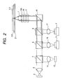
- FIG. 2 is a view of the configuration of an optical pickup device for explaining the principle of the present invention.
- the same components as those in FIG. 1 are denoted by the same reference numerals.
- an objective lens 1 is designed such that the wave front aberration to light having a wavelength ⁇ 0 corresponding to a next generation DVD having a used wavelength ⁇ 0 of 405 nm, a NA of 0.85, and a signal plane protecting substrate thickness of 0.1 mm is minimum on the signal plane of a next generation DVD when the light is incident as a parallel light beam.
- a DVD hologram module 3 and a CD hologram module 4, in each of which light receiving and emitting units are packaged, are used as DVD and CD light sources.
- a light beam radiated from a next generation DVD semiconductor laser 5 is transformed into a parallel light beam by a collimator lens 6, passes through a deflection beam splitter 7 and DVD and CD dichroic prisms 8 and 9 for light beam separation, and changes its direction 90° by a prism 10.
- a wavelength plate 11 changes the state of polarization of the light beam from linear polarization into circular polarization, and a light beam limiting element restricts the diameter of the light beam to a light beam diameter ( ⁇ 0) commensurate with the NA for the next generation DVD.
- the light beam passes through a phase correcting element 13A without changing its parallel light beam state (with an equiphase wave surface kept planar), comes incident on the objective lens 1, and is focused on the signal plane of an optical recording medium (next generation DVD) 2-1, thereby recording and/or playing back information.
- a light beam reflected from the optical recording medium 2-1 is transformed into a circularly polarized light beam having an opposite rotational direction and is transformed into a parallel light beam by the objective lens 1.
- the wavelength plate 11 changes the state of polarization of the light beam from circular polarization into linear polarization such that the resultant linearly polarized light beam is orthogonal to the original linearly polarized light beam.
- the light beam changes its direction 90° by the prism 10, is reflected by the deflection beam splitter 7, and is focused on a light receiving element 15 by a detecting lens 14.
- a light beam having a wavelength ⁇ 1 of 650 nm radiated from the DVD hologram module 3 is transformed into a parallel light beam by a coupling lens 16, is reflected by the dichroic prism 8, passes through the deflection beam splitter 7, and changes its direction 90° by the prism 10.
- the wavelength plate 11 changes the state of polarization of the light beam from linear polarization into circular polarization.
- the light beam limiting element 18 restricts the diameter of the light beam to a light beam diameter ( ⁇ 1) commensurate with the NA for a DVD and restricts the light beam to parts corresponding to cross sections of light beam components incident on toric first and third phase correcting zones (to be described later) provided in the phase correcting element 13A.
- the phase correcting element 13A corrects the spherical aberration to the light beam.
- the light beam comes incident on the objective lens 1 and is focused on the signal plane of an optical recording medium (DVD) 2-2, thereby recording and/or playing back information.
- a light beam reflected from the optical recording medium 2-2 is transformed into a circularly polarized light beam having an opposite rotational direction and is transformed into a parallel light beam by the objective lens 1 and phase correcting element 13A.
- the wavelength plate 11 changes the state of polarization of the light beam from circular polarization into linear polarization such that the resultant linearly polarized light beam is orthogonal to the original linearly polarized light beam.
- the light beam changes its direction 90° by the prism 10, is reflected by the dichroic prism 8, and is focused on a light receiving element of the DVD hologram module 3 by the coupling lens 16.
- a light beam having a wavelength ⁇ 2 of 705 nm radiated from the CD hologram module 4 is transformed into a parallel light beam by a coupling lens 17, is reflected by the dichroic prism 9, and changes its direction 90° by the prism 10.
- the wavelength plate 11 changes the state of polarization from linear polarization into circular polarization.
- the light beam limiting element 18 restricts the diameter of the light beam to a light beam diameter ( ⁇ 2) commensurate with the NA for a CD and restricts the light beam to parts corresponding to cross sections of light beam components incident on toric second and disciform fourth phase correcting zones (to be described later) provided in the phase correcting element 13A.
- the phase correcting element 13A corrects the spherical aberration to the light beam.
- the light beam comes incident on the objective lens 1 and is focused on the signal plane of an optical recording medium (CD) 2-3, thereby recording and/or playing back information.
- a light beam reflected from the optical recording medium 2-3 is transformed into a circularly polarized light beam having an opposite rotational direction and is transformed into a parallel light beam by the objective lens 1 and phase correcting element 13A.
- the wavelength plate 11 changes the state of polarization of the light beam from circular polarization into linear polarization such that the resultant linearly polarized light beam is orthogonal to the original linearly polarized light beam.
- the light beam changes its direction 90° by the prism 10, is reflected by the dichroic prism 9, and is focused on a light receiving element of the CD hologram module 4 by the coupling lens 17.
- specific values represented by ⁇ 0 to ⁇ 2 are 3.1 mm, 2.2 mm, and 1.8 mm, respectively.
- the light beam limiting element 18 and phase correcting element 13A are located backward and forward such that the phase correcting element 13A is nearer the objective lens in relation to the light beam limiting element 18.
- the phase correcting element 13A is arranged to be perpendicular to the light axis of the objective lens 1, and parallel light beams having the wavelengths of ⁇ 0, ⁇ 1, and ⁇ 2 for the next generation DVD, DVD, and CD perpendicularly come incident on the phase correcting element 13A.
- the phase correcting element 13A is formed in the shape of a square plate, and FIG. 3 shows a plan view of the phase correcting element 13A as seen from a direction of the light axis.
- the phase correcting element 13A is formed such that an external size L is larger than the diameter of a circular region, ⁇ 0. Assume here that L is, for example, 3.8 mm.
- the phase correcting element 13A has thereinside a toric first phase correcting zone (W1) which is centered on the light axis and has an outer diameter of ⁇ 1 and an inner diameter of ⁇ 2 and a disciform second phase correcting zone (W2) which is centered on the light axis and has an outer diameter of ⁇ 2.
- Reference characters ⁇ 0, ⁇ 1, and ⁇ 2 denote values for light beam diameters commensurate with the Nas: NA0, NA1, and NA2, for the next generation DVD, DVD, and CD, and the relation ⁇ 0 > ⁇ 1 > ⁇ 2 holds.
- the first phase correcting zone W1 corrects the spherical aberration to a light beam for the DVD by phase correction while the second phase correcting zone W2 corrects the spherical aberration to a light beam for the CD by phase correction.
- a toric zone (W0) which is centered on the light axis and has an outer diameter of ⁇ 0 and an inner diameter of ⁇ 1 is a transparent region and allows a light beam having the wavelength ⁇ 0 corresponding to the next generation DVD to pass therethrough without changing its parallel light beam state (with an equiphase wave surface kept planar).
- the light beam limiting element 18 is also formed in the shape of a square plate and is arranged to be perpendicular to the light axis of the objective lens 1. Parallel light beams having the wavelengths of ⁇ 0, ⁇ 1, and ⁇ 2 for the next generation DVD, DVD, and CD perpendicularly come incident on the light beam limiting element 18.
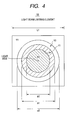
- FIG. 4 shows a plan view of the light beam limiting element 18 as seen from the direction of the light axis.
- the light beam limiting element 18 is formed such that an external size L1 is larger than any one of the light beam diameters of parallel light beams having the wavelengths of ⁇ 0, ⁇ 1, and ⁇ 2 for the next generation DVD, DVD, and CD. Assume here that L1 is, for example, 3.8 mm.
- the light beam limiting element 18 has thereinside first and second transparent regions Y1 and Y2 having wavelength selectivity which are centered on the light axis and have the same shapes and sizes as the first and second phase correcting zones W1 and W2 of the phase correcting element 13A and a toric outer transparent region Y0 having wavelength selectivity which has an outer diameter of ⁇ 0 and an inner diameter of ⁇ 1. Outside the outer transparent region Y0 having wavelength selectivity is a blocking zone YY, which blocks any one of light beams having the wavelengths of ⁇ 0, ⁇ 1, and ⁇ 2 for the next generation DVD, DVD, and CD.
- the outer transparent region YY having wavelength selectivity allows the wavelength ⁇ 0 for the next generation DVD to pass therethrough and blocks the wavelengths of ⁇ 1 and ⁇ 2 for the DVD and CD.
- the first transparent region Y1 having wavelength selectivity allows the wavelengths of ⁇ 0 and ⁇ 1 for the next generation DVD and DVD to pass therethrough and blocks the wavelength ⁇ 2 for the CD.
- the second transparent region Y2 having wavelength selectivity allows the wavelengths of ⁇ 0 and ⁇ 2 for the next generation DVD and CD to pass therethrough and blocks the wavelength ⁇ 1 for the DVD.
- the wavelength ⁇ 0 for the next generation DVD is limited to within a range which has a light beam diameter of ⁇ 0 centered on the light axis and comes incident on the first and second phase correcting zones W1 and W2 and zone W0 of the phase correcting element 13A (see FIG. 5).
- the wavelength ⁇ 1 for the DVD is limited to within a range which has a light beam diameter of ⁇ 1 centered on the light axis, is also limited to a part whose diameter falls within the range of ⁇ 1 to ⁇ 2, and comes incident on the first phase correcting zone W1 of the phase correcting element 13A (see FIG. 6).
- the wavelength ⁇ 2 for the CD is limited to a range which has a light beam diameter of ⁇ 2 centered on the light axis and comes incident on the second phase correcting zone W2 of the phase correcting element 13A (see FIG. 7).
- phase correcting zones W1 and W2 are each a diffraction optical zone exhibiting a pseudo-kinoform shape having stepped structures with two or more steps.
- r be the distance from the light axis measured in a direction perpendicular to the light axis
- ⁇ be a used wavelength.
- An optical path difference function ⁇ (r) defined by the formula below which gives a phase shift for correcting spherical aberration for each of the DVD and CD is determined by the spherical aberration with respect to the distance r from the light axis for the DVD or CD.
- ⁇ r m ⁇ / 2 ⁇ ⁇ ⁇ a 1 ⁇ r 2 + a 2 ⁇ r 4 + a 3 ⁇ r 6 + ⁇ ⁇ ⁇
- ⁇ is a wavelength to be corrected
- the zone W1 is intended for the DVD
- the zone W2 is intended for the CD
- m is a specific diffraction order used which generally has a value of -1 or +1
- a 1 , a 2 , a 3 ,... are each a predetermined optical path difference coefficient determined by the configuration of an optical system.
- the optical path difference function ⁇ (r) is as shown in, e.g., FIG. 8(1). Even if an integer multiple of the wavelength ⁇ (in phasic terms, an integer multiple of 2 ⁇ ) is added to or subtracted from the optical path difference function, an optical path difference function equivalent thereto can be acquired. Accordingly, letting ⁇ F(r) be an optical path difference function obtained by transforming ⁇ (r) by adding an integer multiple of the wavelength ⁇ to or subtracting it from ⁇ (r) such that the value of the optical path difference function falls within the range of 0 to ⁇ , ⁇ F(r) is as shown in FIG. 8(2).
- T r ⁇ F r / n ( ⁇ ) - 1 (shown in FIG. 8(3)). If a structure represented by the formula (2) is formed on a substrate having a uniform thickness, the substrate has a diffraction optical structure having grooves concentrically formed around the light axis in which maximum depths D of the grooves are fixed at ⁇ /(n( ⁇ ) - 1), and groove pitches P decrease with an increase of r.
- a parallel light beam perpendicularly incident on the concentric diffraction optical zones with the groove pitches P which gradually decrease from the inner circumferential side to the outer circumferential side, has a diffraction angle which gradually increases from the inner circumferential side to the outer circumferential side and thus emits a divergent light beam or convergent light beam. Accordingly, it is possible to treat the concentric diffraction optical zones with the continuously-varying groove pitches P as an optical element which bends the traveling direction of light like a lens.
- a pseudo-kinoform shape having stepped structures with two or more steps in cross section which is made to resemble a kinoform shape, as shown in FIG. 9, is generally adopted.
- the diffraction efficiency is determined by the number of steps.
- the diffraction efficiency is 41% in the case of two steps, is 81% in the case of four steps, is 95% in the case of eight steps, and reaches 99% in the case of 16 steps.
- reference characters K and M denote a front surface (a surface opposing the light beam limiting element 18) and a back surface (a surface opposing the objective lens 1) of the phase correcting element 13A.
- the stepped structures are formed on the back surface side, and a light beam as a parallel light beam comes incident from the front surface side.
- the groove pitches P of the stepped structures are so set as to correct the spherical aberration to a light beam as a parallel light beam having the wavelength ⁇ 1 for the DVD, and it suffices to set the step height h of the stepped structures such that the phase shift ⁇ becomes an integer multiple of 2 ⁇ with respect to the wavelength ⁇ 0 for the next generation DVD (although the maximum depth D of the grooves deviates from ⁇ 1/(n( ⁇ 1) - 1), a decrease of diffraction efficiency can be suppressed by setting the number of steps and the height h such that the maximum depth D becomes close to an integer multiple of ⁇ 1/(n( ⁇ 1) - 1)).
- the second phase correcting zone W2 corrects spherical aberration to a light beam as a parallel light beam having the wavelength ⁇ 2 for the CD
- the step height h of the stepped structures is set such that the phase shift ⁇ becomes an integer multiple of 2 ⁇ with respect to the wavelength ⁇ 0 for the next generation DVD (although the maximum depth D of the grooves deviates from ⁇ 2/(n( ⁇ 2) - 1), a decrease of diffraction efficiency can be suppressed by setting the number of steps and the height h such that the maximum depth D becomes close to an integer multiple of ⁇ 2/(n( ⁇ 2) - 1)).
- zone W0 does, not have stepped structures in cross section, is made flush with the upper surface or bottom surface of the stepped structures of the first phase correcting zone W1 (see reference character A or B in FIG. 9), and the thickness of the phase correcting element 13A with the stepped structures excluded is made the same both in the zone W0 and in the first phase correcting zone W1.
- a light beam for the next generation DVD does not change its parallel light beam state in all of the zones W0 to W2 when it passes through the phase correcting element 13A.
- n ( ⁇ 0) is 1.530196
- n ( ⁇ 1) is 1.514520
- n ( ⁇ 2) is 1.511183.
- the number of steps may be set to 5; the step height h, 0.764 ⁇ m; and the maximum groove depth D, 3.819 ⁇ m, for example.
- the second phase correcting zone W2 is configured to have a pseudo-kinoform shape, the number of steps may be set to 4; the step height h, 0.764 ⁇ m; and the maximum groove depth D, 3.055 ⁇ m, for example.
- the glass material for the phase correcting element 13A including the phase correcting zones is BK7
- the number of steps of the first phase correcting zone W1 is 5
- the step height h is 0.764 ⁇ m
- the maximum groove depth D is 3.819 ⁇ m
- the number of steps of the second phase correcting zone W2 is 4
- the step height h is 0.764 ⁇ m
- the maximum groove depth D is 3.055 ⁇ m.
- the first phase correcting zone W1 is expanded to include the second phase correcting zone W2
- the first transparent region Y1 having wavelength selectivity of the light beam limiting element 18 is expanded correspondingly to include the second transparent region Y2 having wavelength selectivity, and all of ranges within which a diameter ⁇ centered on the light axis of the phase correcting element 13A satisfies ⁇ 1 ⁇ ⁇ are configured to have a pseudo-kinoform shape for correcting the spherical aberration to the wavelength ⁇ 1 for the DVD.
- the optical path and point image light intensity distribution when a light beam for the DVD is focused on the signal plane of the optical recording medium (DVD) 2-2 become as shown in FIGS. 10 and 11. It is clear from FIGS.
- the second phase correcting zone W2 is expanded to include the first phase correcting zone W1
- the second transparent region Y2 having wavelength selectivity of the light beam limiting element 18 is expanded correspondingly to include the first transparent region Y1 having wavelength selectivity, and all of the ranges; within which the diameter ⁇ centered on the light axis of the phase correcting element 13A satisfies ⁇ 2 ⁇ ⁇ are configured to have a pseudo-kinoform shape for correcting the spherical aberration to the wavelength ⁇ 2 for the CD.
- the optical path and point image light intensity distribution when a light beam for the CD is focused on the signal plane of the optical recording medium (CD) 2-3 become as shown in FIGS. 12 and 13. It is clear from FIGS. 12 and 13 that the spherical aberration can be corrected.
- a phase correcting zone is divided such that it can phase-correct both the wavelength ⁇ 1 for the DVD and the wavelength ⁇ 2 for the CD alone, and the first and second phase correcting zones W1 and W2 are provided exclusively for the wavelengths ⁇ 1 and ⁇ 2, respectively.
- the first and second transparent regions Y1 and Y2 having wavelength selectivity are provided corresponding to the first and second phase correcting zones W1 and W2.
- the optical path and point image light intensity distribution when the optical pickup device in FIG. 2 using the phase correcting element 13A in FIG. 3 and the light beam limiting element 18 in FIG. 4 focuses a light beam having the wavelength ⁇ 1 for the DVD on the signal plane of the optical recording medium (DVD) 2-2 become as shown in FIGS. 14 and 15.
- the spot diameter of a main lobe ML is small while the intensity of each side lobe SL is high. This is a phenomenon called a super-resolution effect which is caused by making contribution on the periphery of a light beam diameter larger than near the center.
- a super-resolution effect is well-known as a method for making a spot diameter on the optical recording medium signal plane not more than a diffraction limit.
- phase correcting element 13A in FIG. 3 cannot be put to practical use without change.
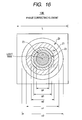
- FIG. 16 is a plan view of a phase correcting element according to the embodiment of the present invention, as seen from the direction of the light axis.
- FIG. 16 shows an example of a phase correcting element in which the problem of crosstalk caused by a super-resolution effect is ameliorated.
- an apodization effect which is an effect opposite to a super-resolution effect, is used.
- An apodization effect is embodied by making contribution near the center of a light beam diameter larger than on the periphery.
- a phase correcting element 13B is formed in the shape of a square plate and is formed such that an external size L is larger than the diameter of a circular region, ⁇ 0.
- the phase correcting element 13B has thereinside a toric first phase correcting zone (Z1) which is centered on the light axis and has an outer diameter of ⁇ 1 and an inner diameter of ⁇ 2, a toric second phase correcting zone (Z2) which is centered on the light axis and has an outer diameter of ⁇ 2 and an inner diameter of ⁇ 3 ( ⁇ 2 > ⁇ 3 > 0), a toric third phase correcting zone (Z3) which is centered on the light axis and has an outer diameter of ⁇ 3 and an inner diameter of ⁇ 4 ( ⁇ 3 > ⁇ 4 > 0), and a disciform fourth phase correcting zone (Z4) which is centered on the light axis and has an outer diameter of ⁇ 4.
- the first phase correcting zone Z1 is configured to be the same as the first phase correcting zone W1 in FIG. 3, and the third phase correcting zone Z3 is configured to be the same as a part whose diameter ⁇ satisfies ⁇ 3 ⁇ ⁇ ⁇ ⁇ 4 when the first phase correcting zone W1 is hypothetically expanded such that the inner diameter becomes ⁇ 4.
- the first and third phase correcting zones Z1 and Z3 are diffraction optical zones, each exhibiting a pseudo-kinoform shape having stepped structures in cross section.
- Groove pitches P of the stepped structures are so set as to correct the spherical aberration to a light beam having the wavelength ⁇ 1 for the DVD by phase correction, and a step height h of the stepped structures is set such that a phase shift ⁇ becomes an integer multiple of 2 ⁇ with respect to the wavelength ⁇ 0 for the next generation DVD (although a maximum depth D of grooves deviates from ⁇ 1/(n( ⁇ 1) - 1), a decrease of diffraction efficiency can be suppressed by setting the number of steps and the height h such that the maximum depth D becomes close to an integer multiple of ⁇ 1/(n( ⁇ 1) - 1)).
- the second phase correcting zone Z2 is configured to be the same as a part whose diameter ⁇ satisfies ⁇ 2 ⁇ ⁇ ⁇ ⁇ 3 of the second phase correcting zone W2 in FIG. 3, and the fourth phase correcting zone Z4 is configured to be the same as a part whose diameter ⁇ satisfies ⁇ 4 ⁇ ⁇ ⁇ 0 of the second phase correcting zone W2.
- the second and fourth phase correcting zones Z2 and Z4 are diffraction optical zones, each exhibiting a pseudo-kinoform shape having stepped structures in cross section.
- the groove pitches P of the stepped structures are so set as to correct the spherical aberration to a light beam having the wavelength ⁇ 2 for the CD by phase correction, and the step height h of the stepped structures is set such that the phase shift ⁇ becomes an integer multiple of 2 ⁇ with respect to the wavelength ⁇ 0 for the next generation DVD (although the maximum depth D of grooves deviates from ⁇ 2/(n( ⁇ 2) - 1), a decrease of diffraction efficiency can be suppressed by setting the number of steps and the height h such that the maximum depth D becomes close to an integer multiple of ⁇ 2/(n( ⁇ 2) - 1)).
- a part as a zone Z0 whose diameter ⁇ satisfies ⁇ 0 ⁇ ⁇ ⁇ ⁇ 1 is the same as the zone W0 in FIG. 3 and is a zone transparent to a light beam having the wavelength ⁇ 0 corresponding to the next generation DVD.
- ⁇ 3 only needs to be set to be not more than 0.9 ⁇ ⁇ 2 in order to achieve good point image light intensity distribution and is preferably set to approximately 0.85 ⁇ ⁇ 2.
- FIG. 17 is a plan view of a light beam limiting element 18B which is used in combination with the phase correcting element 13B, as seen in the direction of the light beam.
- the light beam limiting element 18B is also formed in the shape of a square plate, and parallel light beams having the wavelengths of ⁇ 0, ⁇ 1, and ⁇ 2 for the next generation DVD, DVD, and CD perpendicularly come incident on the beam restriction element 18B.
- the light beam limiting element 18B is formed such that an external size L1 is the same as that of the light beam limiting element 18 in FIG. 4 and is larger than any one of the light beam diameters of parallel light beams having the wavelengths of ⁇ 0, ⁇ 1, and ⁇ 2 for the next generation DVD, DVD, and CD.
- the light beam limiting element 18B has thereinside first to fourth transparent regions X1 to X4 having wavelength selectivity which are centered on the light axis and have the same shapes and sizes as the first to fourth phase correcting zones Z1 to Z4 of the phase correcting element 13B and a toric outer transparent region X0 having wavelength selectivity which has an outer diameter of ⁇ 0 and an inner diameter of ⁇ 1. Outside the outer transparent region X0 having wavelength selectivity is a blocking zone XX, which blocks any one of light beams having the wavelengths of ⁇ 0, ⁇ 1, and ⁇ 2 for the next generation DVD, DVD, and CD.
- the outer transparent region X0 having wavelength selectivity allows the wavelength ⁇ 0 for the next generation DVD to pass therethrough and blocks the wavelengths of ⁇ 1 and ⁇ 2 for the DVD and CD.
- the first and third transparent regions X1 and X3 having wavelength selectivity allow the wavelengths of ⁇ 0 and ⁇ 1 for the next generation DVD and DVD to pass therethrough and block the wavelength ⁇ 2 for the CD.
- the second and fourth transparent regions X2 and X4 having wavelength selectivity allow the wavelengths of ⁇ 0 and ⁇ 2 for the next generation DVD and CD to pass therethrough and block the wavelength ⁇ 1 for the DVD.
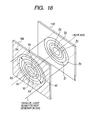
- the wavelength ⁇ 0 for the next generation DVD is limited to within a range which has a light beam diameter of ⁇ 0 centered on the light axis and comes incident on the first to fourth phase correcting zones Z1 to Z4 and the zone Z0 of the phase correcting element 13B (see FIG. 18).
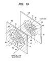
- the wavelength ⁇ 1 for the DVD is limited to within a range which has a light beam diameter of ⁇ 1 centered on the light axis and is also limited to a part whose diameter falls within the range of ⁇ 1 to ⁇ 2 and a part whose diameter falls within the range of ⁇ 3 to ⁇ 4.
- the wavelength ⁇ 1 comes incident on the first and third phase correcting zones Z1 and Z3 of the phase correcting element 13B (see FIG. 19).
- the wavelength ⁇ 2 for the CD is limited to within a range which has a light beam diameter of ⁇ 2 centered on the light axis and is also limited to a part whose diameter falls within the range of ⁇ 2 to ⁇ 3 and a part whose diameter falls within the range of not more than ⁇ 4.
- the wavelength ⁇ 2 comes incident on the second and fourth phase correcting zones Z2 and Z4 of the phase correcting element 13B (see FIG. 20).
- the optical path and point image light intensity distribution when a light beam having the wavelength ⁇ 1 for the DVD is focused on the signal plane of the optical recording medium (DVD) 2-2 become as shown in FIGS. 21 and 22.
- the optical path and point image light intensity distribution when a light beam having the wavelength ⁇ 2 for the CD is focused on the signal plane of the optical recording medium (CD) 2-3 become as shown in FIGS. 23 and 24.
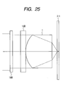
- the optical path and point image light intensity distribution when a light beam having the wavelength ⁇ 0 for the next generation DVD is focused on the signal plane of the optical recording medium (next generation DVD) 2-1 become as shown in FIGS. 25 and 26. It is clear from FIGS.
- the peak intensities of side lobes SL are reduced to 1/e 2 or less that of a main lobe ML, and a super-resolution effect is ameliorated. It is also clear from FIG. 26 that, as for the next generation DVD, there is no particular problem with the ratio of the peak intensities of side lobes SL to that of a main lobe ML.
- the inner diameter of the first phase correcting zone Z1 is preferably set to approximately 0.85 ⁇ ⁇ 1 in order to achieve good point image light intensity distribution.
- the phase correcting element 13B in FIG. 16 and the light beam limiting element 18B in FIG. 17 if the common objective lens 1, which focuses light beams corresponding to the optical recording media, the next generation DVD, DVD, and CD, is formed such that the wave front aberration to a light beam as a parallel light beam having the wavelength ⁇ 0 for the next generation DVD is minimum on the signal plane of the optical recording medium (next generation DVD) 2-1, the phase correcting element 13B can correct, by phase correction, the spherical aberration to each of light beams except for one specific to the next generation DVD, the two light beams as parallel light beams having the wavelengths ⁇ 1 and ⁇ 2 for the DVD and CD.
- each phase correcting zone of the phase correcting element 13B is configured to be a diffraction optical zone exhibiting a pseudo-kinoform shape having stepped structures with two or more steps in cross section which is made to resemble a kinoform shape, spherical aberration can be corrected with low loss.
- Each step height is set such that a phase shift when a light beam for the next generation DVD passes through one step becomes an integer multiple of 2 ⁇ . Accordingly, even if a light beam for the next generation DVD passes through the phase correcting zones, its parallel light beam state does not change, and the wave front aberration is not exacerbated.
- phase correcting element 13B Since only a light beam for the next generation DVD is allowed to pass through the phase correcting element 13B without changing its parallel beam state, there are not many restrictions on the types of glass materials available for use in the phase correcting element 13B.
- phase correcting zones of the phase correcting element 13B correspond to the NAs of optical recording media having specifications different from one another, the capability to correct spherical aberration is reduced if there is a positional shift between the phase correcting element 13B and the light beam limiting element 18B. Accordingly, it is advisable to form the phase correcting zones and the light beam restriction zones on the two surfaces of a single substrate or fasten the phase correcting element and light beam limiting element together by bonding or the like and integrate them into one piece.
- the amount of phase correction at the distance r from the light axis by the phase correcting element corresponds to the amount of spherical aberration at the distance r from the light axis caused by the objective lens and a protecting substrate of an optical recording medium
- a positional shift between the objective lens and the phase correcting element reduces the capability to correct spherical aberration. Accordingly, it is advisable to cause a holding mechanism for the objective lens to hold the phase correcting element and/or light beam limiting element together with the objective lens so as not to cause a positional shift during operation in focusing and tracking directions of the objective lens.
- each phase correcting zone is configured to be a rectangular diffraction optical zone or a phase correcting zone using a liquid crystal aberration correcting element, instead of being configured to take a pseudo-kinoform shape having stepped structures in cross section, phase correction can be similarly performed.
- phase correcting zone may be formed on an objective lens.
- the present invention can be applied to an optical disk device which plays back data from or/and records data on a plurality of optical recording media, such as a next generation DVD, DVD, or/and CD, having specifications different from one another.
Landscapes
- Physics & Mathematics (AREA)
- Optics & Photonics (AREA)
- Optical Head (AREA)
Applications Claiming Priority (2)
| Application Number | Priority Date | Filing Date | Title |
|---|---|---|---|
| JP2005124332A JP4645894B2 (ja) | 2005-04-21 | 2005-04-21 | 光ピックアップ装置 |
| PCT/JP2006/308682 WO2006115262A1 (fr) | 2005-04-21 | 2006-04-19 | Dispositif de détection optique |
Publications (3)
| Publication Number | Publication Date |
|---|---|
| EP1873770A1 true EP1873770A1 (fr) | 2008-01-02 |
| EP1873770A4 EP1873770A4 (fr) | 2008-12-03 |
| EP1873770B1 EP1873770B1 (fr) | 2011-12-21 |
Family
ID=37214876
Family Applications (1)
| Application Number | Title | Priority Date | Filing Date |
|---|---|---|---|
| EP06732338A Expired - Fee Related EP1873770B1 (fr) | 2005-04-21 | 2006-04-19 | Dispositif de détection optique |
Country Status (6)
| Country | Link |
|---|---|
| US (1) | US7738342B2 (fr) |
| EP (1) | EP1873770B1 (fr) |
| JP (1) | JP4645894B2 (fr) |
| CN (1) | CN101189672B (fr) |
| DE (1) | DE06732338T1 (fr) |
| WO (1) | WO2006115262A1 (fr) |
Cited By (3)
| Publication number | Priority date | Publication date | Assignee | Title |
|---|---|---|---|---|
| WO2009007242A1 (fr) * | 2007-07-09 | 2009-01-15 | Thomson Licensing | Modification de forme d'un point de faisceau lumineux à fonctionnalité entièrement symétrique |
| EP2040257A1 (fr) * | 2007-09-24 | 2009-03-25 | Deutsche Thomson OHG | Modification de la forme d'un point de faisceau lumineux doté d'une fonction push-pull complète |
| EP2168124A4 (fr) * | 2007-04-26 | 2010-08-04 | Ricoh Kk | Dispositif optique de détection et de traitement d'informations |
Families Citing this family (2)
| Publication number | Priority date | Publication date | Assignee | Title |
|---|---|---|---|---|
| CN105890643B (zh) * | 2016-05-16 | 2018-03-06 | 中国电子科技集团公司第二十三研究所 | 一种用于光程差测试仪的校准装置及校准方法 |
| EP3658014B1 (fr) * | 2017-09-26 | 2026-04-01 | Apple Inc. | Architecture concentrique pour détection optique |
Family Cites Families (12)
| Publication number | Priority date | Publication date | Assignee | Title |
|---|---|---|---|---|
| US5930214A (en) | 1994-01-19 | 1999-07-27 | Kabushiki Kaisha Toshiba | Recording/reproducing optical head apparatus compatible with different optical media |
| JP3435249B2 (ja) * | 1994-03-11 | 2003-08-11 | 株式会社東芝 | 光学ヘッド装置およびレンズ |
| JPH09145995A (ja) * | 1995-11-27 | 1997-06-06 | Konica Corp | 光情報記録媒体の記録再生用光学系 |
| EP1215666B1 (fr) * | 1996-10-31 | 2004-11-24 | SANYO ELECTRIC Co., Ltd. | Dispositif de lecture optique |
| JPH11194207A (ja) * | 1997-12-26 | 1999-07-21 | Fuji Photo Optical Co Ltd | 回折型フィルタ |
| TW432225B (en) | 1998-06-03 | 2001-05-01 | Konishiroku Photo Ind | Optical pickup apparatus |
| JP2000056216A (ja) * | 1998-06-03 | 2000-02-25 | Konica Corp | 光ピックアップ用光学系および光ピックアップ装置 |
| US7006411B2 (en) * | 2001-06-13 | 2006-02-28 | Ricoh Company, Ltd. | Optical pickup unit having electro-optical element and information recording and reproduction apparatus |
| DE60330817D1 (de) | 2002-02-27 | 2010-02-11 | Ricoh Kk | Optischer Lesekopf und optische Informationsverarbeitungsvorrichtung |
| JP2004327005A (ja) | 2003-04-11 | 2004-11-18 | Sankyo Seiki Mfg Co Ltd | 光ヘッド装置、回折素子、および回折素子の製造方法 |
| JP2005011466A (ja) * | 2003-06-20 | 2005-01-13 | Victor Co Of Japan Ltd | 光ピックアップ装置 |
| JP2005085340A (ja) * | 2003-09-05 | 2005-03-31 | Victor Co Of Japan Ltd | 光ピックアップ装置 |
-
2005
- 2005-04-21 JP JP2005124332A patent/JP4645894B2/ja not_active Expired - Fee Related
-
2006
- 2006-04-19 US US11/918,625 patent/US7738342B2/en active Active
- 2006-04-19 DE DE06732338T patent/DE06732338T1/de active Pending
- 2006-04-19 WO PCT/JP2006/308682 patent/WO2006115262A1/fr not_active Ceased
- 2006-04-19 CN CN2006800135591A patent/CN101189672B/zh not_active Expired - Fee Related
- 2006-04-19 EP EP06732338A patent/EP1873770B1/fr not_active Expired - Fee Related
Cited By (3)
| Publication number | Priority date | Publication date | Assignee | Title |
|---|---|---|---|---|
| EP2168124A4 (fr) * | 2007-04-26 | 2010-08-04 | Ricoh Kk | Dispositif optique de détection et de traitement d'informations |
| WO2009007242A1 (fr) * | 2007-07-09 | 2009-01-15 | Thomson Licensing | Modification de forme d'un point de faisceau lumineux à fonctionnalité entièrement symétrique |
| EP2040257A1 (fr) * | 2007-09-24 | 2009-03-25 | Deutsche Thomson OHG | Modification de la forme d'un point de faisceau lumineux doté d'une fonction push-pull complète |
Also Published As
| Publication number | Publication date |
|---|---|
| US7738342B2 (en) | 2010-06-15 |
| CN101189672A (zh) | 2008-05-28 |
| DE06732338T1 (de) | 2008-06-26 |
| EP1873770B1 (fr) | 2011-12-21 |
| US20090059768A1 (en) | 2009-03-05 |
| EP1873770A4 (fr) | 2008-12-03 |
| JP2006302433A (ja) | 2006-11-02 |
| CN101189672B (zh) | 2010-10-13 |
| WO2006115262A1 (fr) | 2006-11-02 |
| JP4645894B2 (ja) | 2011-03-09 |
Similar Documents
| Publication | Publication Date | Title |
|---|---|---|
| US8178010B2 (en) | Optical device and method of producing the same | |
| EP1788564B1 (fr) | Lentille d'objectif complexe, tête optique, appareil d'information optique, lecteur de disque optique d'ordinateur, système de navigation pour voiture et serveur de disque optique | |
| US8279737B2 (en) | Diffraction grating, aberration correction element and optical head device | |
| US7796490B2 (en) | Optical pickup and optical information processing apparatus | |
| US7636290B2 (en) | Optical element, optical objective element, and optical pickup apparatus having diffractive structure and optical difference giving structure | |
| US7782735B2 (en) | Optical pickup device capable of handling a plurality of laser light beams having different wavelengths | |
| JP4016395B2 (ja) | 複数波長用回折格子および複数波長用回折格子を用いた光ピックアップ装置ならびに光ディスク装置 | |
| EP1873770B1 (fr) | Dispositif de détection optique | |
| US8064314B2 (en) | Optical head and optical disc device | |
| US7558184B2 (en) | Optical pickup device | |
| US20060262702A1 (en) | Optical pickup device | |
| US20080049582A1 (en) | Optical pickup device | |
| EP1774520B1 (fr) | Partie de diffraction | |
| US20070041287A1 (en) | Optical pickup apparatus capable of detecting and compensating for spherical aberration caused by thickness variation of recording layer | |
| KR101330201B1 (ko) | 광 픽업 장치 및 이를 적용한 광 디스크 드라이브 | |
| JP4507738B2 (ja) | 積層波長板及びそれを用いた光ピックアップ | |
| US7420894B2 (en) | Optical pickup device | |
| JP2005203041A (ja) | 光集積ユニットおよび光ピックアップ装置 | |
| KR100644588B1 (ko) | 고밀도 기록 재생 가능한 광픽업장치 | |
| JP2008010020A (ja) | 光学素子および光ピックアップ | |
| JP2005317063A (ja) | ホログラム素子および光ピックアップ | |
| JP2012146352A (ja) | 光ピックアップおよび光情報処理装置 | |
| KR20080071380A (ko) | 홀로그램 소자 및 이를 채용한 호환형 광픽업 장치 | |
| JP2008204583A (ja) | 光学素子及び光ピックアップ装置 | |
| WO2006043187A1 (fr) | Balayage de support de disque optique multicouche |
Legal Events
| Date | Code | Title | Description |
|---|---|---|---|
| PUAI | Public reference made under article 153(3) epc to a published international application that has entered the european phase |
Free format text: ORIGINAL CODE: 0009012 |
|
| 17P | Request for examination filed |
Effective date: 20071015 |
|
| AK | Designated contracting states |
Kind code of ref document: A1 Designated state(s): DE FR GB |
|
| EL | Fr: translation of claims filed | ||
| RBV | Designated contracting states (corrected) |
Designated state(s): DE FR GB |
|
| DET | De: translation of patent claims | ||
| DAX | Request for extension of the european patent (deleted) | ||
| A4 | Supplementary search report drawn up and despatched |
Effective date: 20081105 |
|
| RIC1 | Information provided on ipc code assigned before grant |
Ipc: G11B 7/125 20060101ALI20081030BHEP Ipc: G11B 7/135 20060101AFI20061113BHEP |
|
| 17Q | First examination report despatched |
Effective date: 20090309 |
|
| GRAP | Despatch of communication of intention to grant a patent |
Free format text: ORIGINAL CODE: EPIDOSNIGR1 |
|
| GRAS | Grant fee paid |
Free format text: ORIGINAL CODE: EPIDOSNIGR3 |
|
| RAP1 | Party data changed (applicant data changed or rights of an application transferred) |
Owner name: KABUSHIKI KAISHA KENWOOD |
|
| RIN1 | Information on inventor provided before grant (corrected) |
Inventor name: KABUSHIKI KAISHA KENWOOD |
|
| RIN1 | Information on inventor provided before grant (corrected) |
Inventor name: THE INVENTOR HAS AGREED TO WAIVE HIS ENTITLEMENT T |
|
| GRAA | (expected) grant |
Free format text: ORIGINAL CODE: 0009210 |
|
| AK | Designated contracting states |
Kind code of ref document: B1 Designated state(s): DE FR GB |
|
| REG | Reference to a national code |
Ref country code: GB Ref legal event code: FG4D |
|
| REG | Reference to a national code |
Ref country code: DE Ref legal event code: R096 Ref document number: 602006026530 Country of ref document: DE Effective date: 20120301 |
|
| REG | Reference to a national code |
Ref country code: DE Ref legal event code: R081 Ref document number: 602006026530 Country of ref document: DE Owner name: JVC KENWOOD CORPORATION, YOKOHAMA-SHI, JP Free format text: FORMER OWNER: KABUSHIKI KAISHA KENWOOD, TOKIO/TOKYO, JP Effective date: 20120430 Ref country code: DE Ref legal event code: R081 Ref document number: 602006026530 Country of ref document: DE Owner name: JVC KENWOOD CORPORATION, YOKOHAMA-SHI, JP Free format text: FORMER OWNERS: KABUSHIKI KAISHA KENWOOD, HACHIOUJI, TOKIO/TOKYO, JP; SHINZOU, TORU, SAGAMIHARA, KANAGAWA, JP Effective date: 20120111 Ref country code: DE Ref legal event code: R081 Ref document number: 602006026530 Country of ref document: DE Owner name: JVC KENWOOD CORPORATION, JP Free format text: FORMER OWNER: KABUSHIKI KAISHA KENWOOD,TORU SHINZOU, , JP Effective date: 20120111 Ref country code: DE Ref legal event code: R081 Ref document number: 602006026530 Country of ref document: DE Owner name: JVC KENWOOD CORPORATION, JP Free format text: FORMER OWNER: KABUSHIKI KAISHA KENWOOD, TOKIO/TOKYO, JP Effective date: 20120430 |
|
| PGFP | Annual fee paid to national office [announced via postgrant information from national office to epo] |
Ref country code: DE Payment date: 20120425 Year of fee payment: 7 |
|
| REG | Reference to a national code |
Ref country code: FR Ref legal event code: TP Owner name: JVC KENWOOD CORPORATION, JP Effective date: 20120705 |
|
| PGFP | Annual fee paid to national office [announced via postgrant information from national office to epo] |
Ref country code: FR Payment date: 20120504 Year of fee payment: 7 Ref country code: GB Payment date: 20120418 Year of fee payment: 7 |
|
| PLBE | No opposition filed within time limit |
Free format text: ORIGINAL CODE: 0009261 |
|
| STAA | Information on the status of an ep patent application or granted ep patent |
Free format text: STATUS: NO OPPOSITION FILED WITHIN TIME LIMIT |
|
| 26N | No opposition filed |
Effective date: 20120924 |
|
| REG | Reference to a national code |
Ref country code: DE Ref legal event code: R097 Ref document number: 602006026530 Country of ref document: DE Effective date: 20120924 |
|
| GBPC | Gb: european patent ceased through non-payment of renewal fee |
Effective date: 20130419 |
|
| PG25 | Lapsed in a contracting state [announced via postgrant information from national office to epo] |
Ref country code: GB Free format text: LAPSE BECAUSE OF NON-PAYMENT OF DUE FEES Effective date: 20130419 Ref country code: DE Free format text: LAPSE BECAUSE OF NON-PAYMENT OF DUE FEES Effective date: 20131101 |
|
| REG | Reference to a national code |
Ref country code: FR Ref legal event code: ST Effective date: 20131231 |
|
| REG | Reference to a national code |
Ref country code: DE Ref legal event code: R119 Ref document number: 602006026530 Country of ref document: DE Effective date: 20131101 |
|
| PG25 | Lapsed in a contracting state [announced via postgrant information from national office to epo] |
Ref country code: FR Free format text: LAPSE BECAUSE OF NON-PAYMENT OF DUE FEES Effective date: 20130430 |