EP1874487B1 - Procede pour produire des elements createurs d'effet de couleurs - Google Patents
Procede pour produire des elements createurs d'effet de couleurs Download PDFInfo
- Publication number
- EP1874487B1 EP1874487B1 EP06724571.2A EP06724571A EP1874487B1 EP 1874487 B1 EP1874487 B1 EP 1874487B1 EP 06724571 A EP06724571 A EP 06724571A EP 1874487 B1 EP1874487 B1 EP 1874487B1
- Authority
- EP
- European Patent Office
- Prior art keywords
- magnetic
- pixels
- carrier substrate
- image
- colour effect
- Prior art date
- Legal status (The legal status is an assumption and is not a legal conclusion. Google has not performed a legal analysis and makes no representation as to the accuracy of the status listed.)
- Expired - Lifetime
Links
Images




Classifications
-
- B—PERFORMING OPERATIONS; TRANSPORTING
- B05—SPRAYING OR ATOMISING IN GENERAL; APPLYING FLUENT MATERIALS TO SURFACES, IN GENERAL
- B05D—PROCESSES FOR APPLYING FLUENT MATERIALS TO SURFACES, IN GENERAL
- B05D3/00—Pretreatment of surfaces to which liquids or other fluent materials are to be applied; After-treatment of applied coatings, e.g. intermediate treating of an applied coating preparatory to subsequent applications of liquids or other fluent materials
- B05D3/20—Pretreatment of surfaces to which liquids or other fluent materials are to be applied; After-treatment of applied coatings, e.g. intermediate treating of an applied coating preparatory to subsequent applications of liquids or other fluent materials by magnetic fields
-
- B—PERFORMING OPERATIONS; TRANSPORTING
- B05—SPRAYING OR ATOMISING IN GENERAL; APPLYING FLUENT MATERIALS TO SURFACES, IN GENERAL
- B05D—PROCESSES FOR APPLYING FLUENT MATERIALS TO SURFACES, IN GENERAL
- B05D5/00—Processes for applying liquids or other fluent materials to surfaces to obtain special surface effects, finishes or structures
- B05D5/06—Processes for applying liquids or other fluent materials to surfaces to obtain special surface effects, finishes or structures to obtain multicolour or other optical effects
- B05D5/065—Processes for applying liquids or other fluent materials to surfaces to obtain special surface effects, finishes or structures to obtain multicolour or other optical effects having colour interferences or colour shifts or opalescent looking, flip-flop, two tones
-
- B—PERFORMING OPERATIONS; TRANSPORTING
- B05—SPRAYING OR ATOMISING IN GENERAL; APPLYING FLUENT MATERIALS TO SURFACES, IN GENERAL
- B05D—PROCESSES FOR APPLYING FLUENT MATERIALS TO SURFACES, IN GENERAL
- B05D2252/00—Sheets
- B05D2252/02—Sheets of indefinite length
-
- B—PERFORMING OPERATIONS; TRANSPORTING
- B05—SPRAYING OR ATOMISING IN GENERAL; APPLYING FLUENT MATERIALS TO SURFACES, IN GENERAL
- B05D—PROCESSES FOR APPLYING FLUENT MATERIALS TO SURFACES, IN GENERAL
- B05D2601/00—Inorganic fillers
- B05D2601/02—Inorganic fillers used for pigmentation effect, e.g. metallic effect
-
- B—PERFORMING OPERATIONS; TRANSPORTING
- B05—SPRAYING OR ATOMISING IN GENERAL; APPLYING FLUENT MATERIALS TO SURFACES, IN GENERAL
- B05D—PROCESSES FOR APPLYING FLUENT MATERIALS TO SURFACES, IN GENERAL
- B05D3/00—Pretreatment of surfaces to which liquids or other fluent materials are to be applied; After-treatment of applied coatings, e.g. intermediate treating of an applied coating preparatory to subsequent applications of liquids or other fluent materials
- B05D3/02—Pretreatment of surfaces to which liquids or other fluent materials are to be applied; After-treatment of applied coatings, e.g. intermediate treating of an applied coating preparatory to subsequent applications of liquids or other fluent materials by baking
- B05D3/0254—After-treatment
-
- B—PERFORMING OPERATIONS; TRANSPORTING
- B05—SPRAYING OR ATOMISING IN GENERAL; APPLYING FLUENT MATERIALS TO SURFACES, IN GENERAL
- B05D—PROCESSES FOR APPLYING FLUENT MATERIALS TO SURFACES, IN GENERAL
- B05D3/00—Pretreatment of surfaces to which liquids or other fluent materials are to be applied; After-treatment of applied coatings, e.g. intermediate treating of an applied coating preparatory to subsequent applications of liquids or other fluent materials
- B05D3/06—Pretreatment of surfaces to which liquids or other fluent materials are to be applied; After-treatment of applied coatings, e.g. intermediate treating of an applied coating preparatory to subsequent applications of liquids or other fluent materials by exposure to radiation
- B05D3/061—Pretreatment of surfaces to which liquids or other fluent materials are to be applied; After-treatment of applied coatings, e.g. intermediate treating of an applied coating preparatory to subsequent applications of liquids or other fluent materials by exposure to radiation using U.V.
- B05D3/065—After-treatment
- B05D3/067—Curing or cross-linking the coating
-
- B—PERFORMING OPERATIONS; TRANSPORTING
- B05—SPRAYING OR ATOMISING IN GENERAL; APPLYING FLUENT MATERIALS TO SURFACES, IN GENERAL
- B05D—PROCESSES FOR APPLYING FLUENT MATERIALS TO SURFACES, IN GENERAL
- B05D3/00—Pretreatment of surfaces to which liquids or other fluent materials are to be applied; After-treatment of applied coatings, e.g. intermediate treating of an applied coating preparatory to subsequent applications of liquids or other fluent materials
- B05D3/06—Pretreatment of surfaces to which liquids or other fluent materials are to be applied; After-treatment of applied coatings, e.g. intermediate treating of an applied coating preparatory to subsequent applications of liquids or other fluent materials by exposure to radiation
- B05D3/068—Pretreatment of surfaces to which liquids or other fluent materials are to be applied; After-treatment of applied coatings, e.g. intermediate treating of an applied coating preparatory to subsequent applications of liquids or other fluent materials by exposure to radiation using ionising radiations (gamma, X, electrons)
Definitions
- the invention relates to a method for producing color effect images on a carrier substrate, to a device for producing a color effect image and to a multilayer body with color effect image.
- Colored iridescent magnetic effect pigments are used for decorative purposes to produce viewing-angle-dependent color effects on the surfaces coated with these pigments.
- the functional principle of the color change is the interference effect that can be observed with thin layers and the orientation of the pigment particles when applied to the surface to be coated by a magnetic field. In this way, groups of pigment particles arranged in the same direction in one orientation can be formed, which can optically delineate against groups with a different orientation or against groups with randomly arranged pigment particles.
- Devices and methods which provide for aligning the magnetic pigment particles by means of permanent magnets, which are arranged below and / or above the substrate to be coated with the pigment particles.
- the WO 02/090002 A2 describes a method for producing colored coated articles by using magnetic pigments. It is envisaged to embed the magnetic pigments in a UV-curable lacquer and to expose the lacquer successively through differently shaped masks, wherein the lacquer is exposed to a differently directed magnetic field before each exposure. By the exposure, the pigments are fixed in the UV-exposed area in their positional orientation predetermined by the applied magnetic field.
- the WO 2004/007095 A2 provides for aligning the magnetic pigments with magnets and / or groups of magnets which, due to their size, arrangement and magnetic polarity, generate magnetic-line characteristics in which the magnetic fluxes of the magnetic field are generated Pigments are aligned a pigmented paint. After curing of the paint, the magnetic pigments are fixed in position. It is further provided to form the magnets with the cross section of the pattern to be printed, for example with a star-shaped cross-section.
- the invention is based on the object of specifying an improved process for producing color effect images and a device for carrying out this process.
- the object of the invention is achieved by providing a method for producing color effect images on a carrier substrate, wherein it is provided that on a magnetizable printing plate a latent magnetic image of magnetic pixels and non-magnetic pixels by means of an electromagnetic printhead with two or more side by side Magnetic heads are generated, wherein magnetic pixels differ in the strength of the magnetic field and / or in the direction of the magnetic field lines, wherein it is provided that on the magnetizable printing form, a carrier substrate having a deposited on the carrier substrate decorative layer with non-spherical, preferably acicular or platelet-shaped magnetic color effect pigments is guided past, so that color effect pigments of the decorative layer by the field line image generated by the magnetic pixels of the magnetizable printing plate in alignment with d a carrier substrate to be changed and that the color effect pigments are fixed in the changed by the field line image of the printing form alignment in the decorative layer.
- a device for producing a color effect image on a carrier substrate wherein it is provided that the device is an application device for applying a decorative layer with non-spherical, preferably acicular or platelet-shaped magnetic color effect pigments in a binder on a carrier substrate, at least one electromagnetic printhead with two or more side by side arranged magnetic heads, one magnetizable Printing form, on which a latent magnetic image of magnetic pixels and non-magnetic pixels is generated, a transport device and a fixing device, that the transport device is designed so that it passes the carrier substrate with the applied decorative layer so on the magnetizable printing form, so in that the color effect pigments of the decorative layer are changed by the magnetic field line image generated by the magnetic pixels of the printing form in their orientation relative to the carrier substrate, and in that the fixing device for fixing the color effect pigments is arranged in the orientation changed by the field line image of the printing plate.
- multilayer bodies having a decorative layer which has non-spherical, preferably needle-shaped or platelet-shaped magnetic color effect pigments, wherein the color effect pigments are arranged in the decorative layer to form a color effect image, it being provided that the color effect image is formed from pixels which are arranged in one Raster line by line and arranged in columns and that the color effect image has color effect pixels in which the color effect pigments are arranged in an orderly spatial position so that the brightness and / or the color of the respective color effect pixel depending on the position of the color effect pigments and / or the viewing direction and / or the wavelength and / or the polarization of the light directed onto the color effect pixel is or is formed.
- the method provides to create a digital record of the color effect image and to use this to generate a latent magnetic image, with the help of which the magnetic color effect pigments are aligned.
- Such a method does not require the manufacture of specially designed magnets, but instead provides for the use of a device that is controllable by a digital data set.
- the inventive method is characterized by speed, high productivity, low cost, high flexibility and long service life and allows design changes with little effort and low cost.
- the multilayer body according to the invention may be formed with further layers, for example with optical and / or electrical functional layers.
- the multi-layer body may be formed as a security element, as it is used to protect documents and / or goods. It can also be provided to provide the multilayer body with additional layers after the color effect image has been applied in further method steps.
- the color effect image has two or more color effect pixels of different types, in which the color effect pigments each in a different orientation to the Carrier substrate are arranged. In this way, rasterized multiple images can be displayed.
- the carrier substrate and the printing forme are moved with the speed and speed matching as long as the color effect pigments in the binder are movable, so that the relative speed between the carrier substrate and the printing plate is zero.
- the carrier substrate may be pressed with rollers to the printing plate, so that the carrier substrate and printing form are moved synchronously.
- magnétique pixels are generated, which differ in the strength of the magnetic field and / or in the direction of the magnetic field lines. In this way, different field line images can be generated with the same arrangement of the magnetic pixels. This also determines the arrangement and distribution of the magnetic pixels on the orientation of the magnetic color effect pigments. It can therefore be provided that juxtaposed magnetic pixels are formed with different orientation.
- the latent magnetic image is formed of a matrix of magnetic pixels
- the course of the magnetic field lines that determine the color effect image by aligning the color effect pigments is essentially determined by the magnetic properties of the magnetic pixels.
- the magnetic pixels can be arranged, for example, to form regions of the field line image in which the magnetic field lines are directed perpendicular to the surface of the carrier substrate or in which the magnetic field lines are parallel to the surface of the carrier substrate.
- the magnetic pixels can also be arranged to form regions of the field line image in which the magnetic field lines are fan-shaped at different angles to the surface of the carrier substrate. It can further be provided that the magnetic pixels are arranged to form regions of the field line image in which the magnetic field lines are directed in an arcuate manner at different angles to the surface of the carrier substrate.
- pixels described above are exemplary of the many possibilities of forming field line images in the context of the method according to the invention. It may further be provided to include non-magnetic pixels, which are covered by the field lines of adjacent magnetic pixels and thereby contribute to the formation of the magnetic field line image.
- the different field line images result in different arrangements of the color effect pigments.
- a region of the color effect image with a vertical arrangement of the color effect pigments appears dark when viewed perpendicularly, and increasingly brighter when obliquely viewed, color effects additionally being able to be formed.
- An area of fan-shaped magnetic color effect pigments creates the illusion of a plastic image in the viewer. Starting from a center line in which the color effect pigments are oriented vertically, in this example, when the color effect image is tilted, the left side of the image is lightened and vice versa.
- An area of color effect pigments aligned in an arcuate manner at different angles to the surface of the carrier substrate forms a bright stripe which travels over the color effect image as it is tilted back and forth.
- the magnetic color effect pigments are nonspherical strip-shaped or rod-shaped pigments having a magnetic core and a shell, which can cause color effects.
- These elongated color effect pigments unlike spherical pigments, can not only arrange along the magnetic field lines, but also align them. Therefore, a first viewing angle-dependent optical effect is already formed by the shape of the color effect pigments regardless of the type of surface coating.
- the nearly point-shaped end faces of the color effect pigments reflect little light and therefore form dark areas when aligned uniformly, while the lateral surfaces of the color effect pigments reflect more light and therefore form bright areas when aligned uniformly.
- a second viewing-angle-dependent optical effect may be caused by a surface coating of the color effect pigments forming optical effects based on refraction, diffraction or polarization.
- the surface coating may, for example, be a thin-layer system which can form the color-shift effect known from oil films, a mirror layer or a cholesteric liquid-crystal layer. In this way, optical effects can be generated which depend on the viewing angle and / or the direction of illumination and / or the wavelength of the light and / or the polarization of the light.
- a color effect image may be generated by including the digital data set of pixels of binary value "1" and pixels of binary value "0".
- the latent magnetic image is thus formed of magnetic and non-magnetic pixels.
- the magnetic color effect pigments are now aligned in the region of a magnetic pixel, while they are arranged in the region of a non-magnetic pixel in a random, random position. Due to the different orientation of the color effect pigments in the two named areas, the areas are optically delimited from each other.
- Color effect pigments arranged on nonmagnetic pixels have no preferred orientation.
- Brightness and / or color value of the non-magnetic pixel may be independent of the viewing and / or illumination direction.
- the brightness and / or color value of the magnetic pixel are dependent on the viewing and / or lighting direction, because they are arranged uniformly or according to a predetermined pattern.
- the magnetic color effect pigments are aligned by the action of magnetic pixels and electromagnetic printheads.
- the magnetic color effect pigments are aligned by a temporal sequence of the action of magnetic pixels and / or electromagnetic printheads.
- the magnetic color effect pigments can thus be brought into the end position in successive steps, in which they can assume intermediate layers, in which they have the desired optical effect.
- the color effect pigments are mobile in the binder, magnetic alignment is not a lazy process. It can therefore also be provided that the magnetic color effect pigments are aligned by a temporary magnetic pulse.
- one of the printheads as a first electromagnetic printhead embracing the printing form, aligns the magnetic color effect pigments parallel to the upper surface of the support substrate, that an electromagnetic erase head forms the non-magnetic pixels, and that the electromagnetic printhead forms the magnetic pixels.
- the printing head encompassing the printhead may have a slot through which the printing form is passed, which may be, for example, designed as an endless belt or as a rotating drum printing form.
- the electromagnetic erase head can advantageously be formed in a line of individually controllable magnetic heads. Such an erase head can delete pixel by pixel, ie form a pixel as a non-magnetic pixel and / or actively bring color effect pigments into an unordered position. It can be provided with the erase head to form the non-magnetic pixels and thereby delete the previously generated pixels and form further non-magnetic pixels to be overwritten with a new magnetic pixel below.
- it is provided to activate the erase head only when the of the previous first print head generated image line is disposed below the erase head.
- electromagnetic printheads which generate the latent magnetic image on the magnetizable printing form, according to a first, the arrangement of the magnetic pixels and non-magnetic pixels descriptive digital data set are driven. In this way, preferably color effect images can be produced in which the arranged in the magnetic pixels color effect pigments are aligned in the same way.
- the first data record is calculated by a computer from a second data record which describes the graphic design of the color effect image.
- the resulting design options of the color effect image are described in detail above.
- the inventive method provides that a decorative layer is applied to the carrier substrate as a decorative layer, in which the magnetic color effect pigments are incorporated in a binder by the latent magnetic image alignable.
- the viscosity of the binder is adjusted so that the color effect pigments can move freely.
- binders acrylates can be provided.
- the solids content may be 20% to 40%, the viscosity may be set at 100 Pa s to 1600 Pa s, preferably at 200 Pa s to 300 Pa s.
- the color effect image formed by the process according to the invention visually stands out from the image background when the decorative layer is applied over a surface or area, because the color effect pigments arranged in the background are arranged in a random position, while the color effect pigments are aligned in a predetermined manner in the area of the color effect image, thus the above cause optical effects described and visually stand out from the neutral image background.
- the color effect pigments are fixed after alignment in the decorative layer by drying or by crosslinking of the binder. Drying here means that the binder is converted from the liquid to the solid state by driving off a solvent component. It
- the binder may also be a binder that can be converted from the liquid to the solid state by a chemical reaction, wherein it may be formed from one or more components.
- the binder is crosslinked by UV irradiation.
- the carrier substrate is fed in and out in a roll-to-roll process.
- the device comprises a first electromagnetic printhead, which surrounds the printing plate and / or the carrier substrate, an electromagnetic erase head, which is arranged after the first electromagnetic printhead, and at least one further electromagnetic printhead, according to the erase head is arranged and whose magnetic field lines are directed parallel to the surface of the printing plate and / or the carrier substrate comprises.
- Two adjacent magnetic pixels can therefore be formed with this device with different magnetic orientation and / or magnetic polarity and / or magnetic force.
- the electromagnetic printheads and / or the electromagnetic erase head have juxtaposed magnetic heads, which form a perpendicular to the transport direction of the printing plate and / or the carrier substrate aligned printing line.
- the number of magnetic heads in a print line is equal to the number of pixels of an image line of the color effect image. In this way, a particularly high printing speed can be achieved because an image line is formed in one step on the magnetic printing plate.
- the electromagnetic printheads and / or the electromagnetic erase head have one or more magnetic heads, which are arranged in a positionally adjustable position along the printing line aligned perpendicular to the transport direction of the printing forme and / or the carrier substrate.
- Pixel-positionable magnetic heads are not subject to the spatial limitations next to each other in the pixel pitch arranged magnetic heads and can therefore be formed, for example, with higher magnetic force.
- the one or more magnetic heads are arranged to be pivotable about an axis parallel to the surface of the carrier film and / or about an axis perpendicular to the surface of the carrier film.
- the magnetic heads are arranged above the printing form and / or above the carrier substrate.
- the magnetic heads are arranged in pairs opposite each other above and below the printing plate and / or the carrier substrate.
- the paired arrangement of the magnetic heads may be advantageous in order to form a particularly strong and homogeneous magnetic field.
- two successive arranged electromagnetic printheads may be provided for the formation of magnetic pixels of different polarity, which are formed of individually controllable magnetic heads with a common ground line.
- Each of the two print heads thus only forms magnetic pixels of one polarity.
- Such a configuration may allow a particularly simple constructive solution, in particular a space-saving design.
- only one such print head with a common ground line can be provided, wherein the formation of the pixels of different magnetic polarity is provided one after the other.
- the erase head and / or the print head or the print heads form a combined head.
- it is determined by the type of control, ie by the current, the current direction and the duration of the current flowing through the magnetic winding of the magnetic head current, whether a driven magnetic head of the combi head is used as an erase head or as a print head.
- the magnetic head for forming the magnetic pixel is driven sequentially, for example, is acted upon in the first sequence with high-frequency alternating current and acts as an erase head and is acted upon in the second sequence with DC and so the elementary magnets of the magnetic pixel in a ordered position perpendicular to the printing plate brings.
- a continuous endless printing forme is provided, wherein the printing forme may be formed, for example, as an endless printing belt or as a printing drum.
- the transport device is designed as a stepper drive, wherein the step size is equal to the image line spacing of the color effect image.
- the transport device is designed as a stepper drive, wherein the step size is equal to the image line spacing of the color effect image.
- the application device for applying the decorative layer is designed as a mechanical printer, for example as a pressure roller or as a squeegee device.
- the pressure roller can be a profiled or an unprofiled pressure roller.
- the pressure roller can be profiled, for example, in the outlines of the color effect image and thus apply the decorative layer to the carrier substrate as a high-pressure roller or as a gravure roller.
- the fixing device has a thermal source for drying the binder of the decorative layer and / or a UV source for crosslinking the binder.
- Fig. 1 shows a schematic representation of a first embodiment of a device 1 according to the invention.
- a soft magnetic pressure belt 11 is stretched horizontally between two spaced-apart transport rollers 11t and is driven continuously by them.
- the soft-magnetic printing tape 11 is a printing tape in which magnetic pixels can be formed by the magnetic coercive force of the printing tape is exceeded in the region of the pixel by the action of an external magnetic field.
- the magnetic pixel is now formed as a result of the uniform orientation of its elementary magnets as a permanent magnet and remains in this state until it by applying an opposite direction polarized magnetic field is restored to its non-magnetic initial state.
- a carrier film 12 is brought in a continuous roll-to-roll process from above to the printing tape 11 and thereby pressed by pressure rollers 13 to the printing tape 11.
- the pressure rollers 13 are in the in Fig. 1 illustrated embodiment arranged so that they press the carrier film 12 and the printing tape 11 on the transport roller 11t and so make the intimate contact between the carrier film 12 and the printing tape 11.
- In the schematic representation in Fig. 1 only two pinch rollers 13 are shown. However, it can be provided to arrange further pressure rollers in pairs opposite one another between the two outer contact points in order to improve the contact between the carrier film 12 and the pressure belt 11.
- an electromagnetic erase head 15 and an electromagnetic printhead 16 are arranged in the flow direction one behind the other, which are connected to a computer station 17, in which a digital record of a color effect image is stored.
- a print head 18 and a fixing device 19 are arranged one behind the other in the flow direction.
- the erase head 15 is, as in Fig. 2 shown in a schematic sectional view, formed of juxtaposed magnetic heads 151.
- the number of magnetic heads 15l may correspond to the number of pixels of an image line of the color effect image.
- the magnetic heads have a soft magnetic core, which is surrounded by one or more windings of an electrical conductor and a magnetic field can train if its electrical conductor is traversed by an electric current. Between two mutually opposite magnetic heads 15 l non-magnetic pixels 11 u can be formed in the printing belt 11 when the magnetic heads are traversed by alternating current. Preferably, a high-frequency alternating current can be provided for this purpose. As in Fig. 1 shown, the erase head 15 is driven by the computer station 17.
- the magnetic heads 151 each arranged in pairs spaced from each other and to guide the printing tape 11 through the slot formed between them. But it can also be provided to arrange the magnetic heads 15 l only on the top or the bottom of the printing tape 11.
- Fig. 3 shows a schematic representation of a section of the printing tape 11 with non-magnetic pixels 11 u, over which color effect pigments 20p are arranged in a disordered, ie in a random position.
- the write head 16 can in principle be designed like the erase head 15, ie be formed in a row of juxtaposed magnetic heads 16s and 16s' (see FIG. Fig. 4 ). Magnetic pixels 11m can be formed in the printing belt 11 between two opposite magnetic-flux-carrying magnetic heads 16s.
- the magnetic heads 16s' are non-current magnetic heads, ie no magnetic field is formed between them.
- the write head 16 becomes, as in Fig. 1 shown, driven by the computer station 17. It can be provided to form magnetic pixels 11 m by selecting the current direction, which differ in the orientation of their magnetic poles from each other. Adjacent magnetic pixels 11m can thus be arranged with the same or with an unequal arrangement of the magnetic poles, whereby different field line courses can be formed between the two magnetic pixels. Adjacent magnetic pixels 11 m with the same orientation of the magnetic poles form repulsive forces, adjacent magnetic pixels 11 m with different orientation of the magnetic poles form attractive forces. The magnetic and non-magnetic pixels form a latent one in the printing plate 11 magnetic image used to align magnetic color effect pigments 20p (see FIG. Fig. 3 ) is determined.
- the printhead 18 is advantageously designed as a digital printhead for applying inks or inks and can be controlled by the computer 17.
- a decorative layer 20 (s. Fig. 3 ) is applied to the carrier substrate 12.
- the decorative layer 20 is formed of the magnetic color effect pigments 20p and a binder.
- the print head 18 can be moved along an image line of the color effect image by a stepping motor (not shown) and in this way apply the decorative layer 20 pixel by pixel.
- the print head 18 may have a plurality of ink reservoir, so that in addition to the decor ink further inks can be applied.
- a visual representation can be printed together with the color effect image, which forms, for example, the environment of the color effect image.
- the digital printhead or a squeegee roller o.ä. be provided to print the carrier film 12 over the entire surface or in strips with the decorative layer 20.
- the viscosity of the binder of the decorative layer 20 in which the color effect pigments 20p are bonded is set so that the color effect pigments 20p in the binder are free to move.
- the binder may be a solution that is curable by evaporation of a solvent. However, it may also be a polymer which can be crosslinked by heat or by UV light.
- the freely movable rod-shaped magnetic color effect pigments 20 p of the decorative layer applied to the carrier film 12 in an unordered position are now aligned along the magnetic field lines of the latent magnetic image formed in the printing belt 11. In this way, the color effect pigments 20p can be brought into a position such that a color effect dependent on the viewing angle and / or the illumination direction is formed, which is described in more detail below.
- the fixing device may have a lamp 191, which may be formed as a thermal source or as a UV source.
- the carrier film 12 and the printing tape 11 in relative silence when they are moved under the print head 18 and through the fixing device 19. Therefore, the magnetic color effect pigments 20p are reliably fixed in position by the magnetic field lines emanating from the printing tape 11 prior to curing of the binder.
- the latent magnetic image deposited on the printing tape 11 is not subject to wear, it may be provided to put the magnetic head 14, the erasing head 15 and the writing head 16 out of operation when the printing tape 11 has been completely described and only to be put back into operation, when the printing tape 11 is to be rewritten.
- Fig. 5 now shows a schematic representation of a section of the printing tape 11 with magnetic pixels 11 m and 11 m ', on which the printed with a decorative layer 20 carrier film 12 is arranged.
- magnetic field lines which are directed perpendicular to the outer surface of the printing tape 11.
- the two adjacent magnetic pixels 11m and 11m ' have different magnetic poles.
- adjacent color effect pigments 20 p are attracted, so that the color effect pigments 20 p are arranged approximately parallel and perpendicular to the carrier film 12.
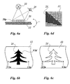
- Fig. 6a to 6c now show which optical effect with the in Fig. 5 shown alignment of the color effect pigments 20p can be formed.
- a color effect image 21 is shown, which is arranged on the carrier film 12. It will, as in Fig. 6a shown in section, illuminated by a arranged above the color effect image 21 light source 22 and observed by a viewer, in whose eye 23 an image of the color effect image 21 is formed. The viewer sees the color effect image 21 at different angles when he pivots it or when he tilts his head accordingly.
- the swivel range of the color effect image is in Fig. 6a denoted by a curved double arrow ⁇ .
- the color effect image 21 appears, as in FIG Fig. 6b shown to the eye 23 of the observer vertical line of sight dark.
- the incident light is now reflected back from the side surfaces of the color effect pigments 20p.
- the color effect image 21 thus appears as in Fig. 6c shown to the eye 23 of the viewer brighter with increasing tilt angle and thereby shows color changes, which may be caused by the coating of the color effect pigments 20p with thin refractive layers.
- Fig. 6d shows an enlarged view of an image section Vld
- Fig. 6b exemplifies the formation of the color effect image 21 from individual pixels in the Fig. 6d are marked as black areas.
- the background of the color effect image is also formed of pixels which are applied to the carrier foil 12 and which are pixels which are not covered with color effect pigments. These pixels are in Fig. 6d shown as white areas.
- the outer edges of the color effect image 21 are stepped stepped because of the formation of pixels, this gradation is not perceptible by the eye of the beholder.
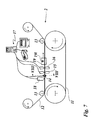
- the Fig. 7 now shows a second embodiment of a device according to the invention. Identical elements are provided with the same reference numerals.
- the carrier film 12 is fed from a roll to the circulating printing belt 11 and brought with this by the pressure rollers 13 to the plant, which face two spaced-apart transport rollers.
- the print head 18, an electromagnetic printhead 14 embracing the print tape, the electromagnetic erase head 15, and the electromagnetic printhead 16 are arranged one behind the other in the running direction of the print tape 11.
- the print head 14 engages, as in the schematic sectional view in Fig. 8 shown, with a yoke-shaped closed core 14j, the printing tape 11.
- the core 14j may be constructed, for example, as a core laminated from Dynamo sheet.
- the core 14j is partially surrounded by a wire winding 14 w, which forms a magnetic field when current flows.
- the magnetic field is directed so that the magnetic field lines extend transversely to the direction of movement and parallel to the outside or to the inside of the printing belt 11.
- both the Elementary magnets of the printing tape 11 and the applied on the carrier film 12 in the decorative layer color effect pigments are both the Elementary magnets of the printing tape 11 and the applied on the carrier film 12 in the decorative layer color effect pigments.
- the magnetic heads of the erasing head 15 intended to form non-magnetic pixels are excited with preferably high-frequency alternating current. In this way, the color effect pigments aligned by the print head 14 are again brought into an unordered position in these pixels.
- the magnetic heads of the print head 16 driven by the computer station 17 When the image line is now under the print head 16, the magnetic heads of the print head 16 driven by the computer station 17 generate magnetic pixels whose field lines do not run parallel to the surface of the print tape 11.
- the field lines of the magnetic heads of the print head 16 are directed perpendicular to the surface of the printing tape 11 and to the surface of the carrier film 12, so that the color effect pigments are erected along the field lines.
- the magnetic field of the magnetic head can be adjusted so that it is not able to completely upright the color effect pigments under it. It may be provided to determine the process parameters by test series, wherein the position of the pixels to adjacent pixels is to be considered.
- the printheads 14 and 16 and the erase head 15 are constantly in operation and thereby controlled by the computer station 17 synchronously to the printer 18.
- the duration of the activation of the magnetic heads can be varied, wherein the dynamic Control can be particularly advantageous at high transport speed of the carrier substrate.
- the erase head 15 and / or the printhead 16 may be provided to form the erase head 15 and / or the printhead 16 only with at least one magnetic head, which is driven by a stepper motor, can be moved along an image line.
- a magnetic head may also be pivotable, so that it can align the color effect pigments obliquely in a particularly simple manner.
- the fixing device 19 is disposed behind the write head 16.
- the printing drum may be formed of non-magnetic material and be wrapped by the film 12.
- the print head 18, the encompassing electromagnetic printhead 14, the electromagnetic erase head 15 and the electromagnetic printhead 16 are accordingly arranged one behind the other at the circumference of the printing drum in the direction of rotation of the printing drum, ie the film 12 passes in the order indicated the printheads or the erasing head.
- Fig. 9 now shows a schematic representation of a section of the printing tape 11 with magnetic pixels 11m, the magnetic field lines are aligned obliquely to the surface of the printing tape 11.
- the oblique orientation was created by forming the magnetic pixels 11m successively with the print head 14 and the print head 16, as described above.
- the elementary magnets of the pixels 11 m were aligned with the print head 14 parallel to the surface of the carrier film 12 and then erected with the print head 16 by about 45 °.
- the color effect pigments 20p are also inclined at about 45 ° to the surface of the carrier sheet 12.
- the Fig. 10a to 10c now show the optical effect, with the in Fig. 9 described oblique arrangement of the color effect pigments 20p can be formed.
- the color effect pigments 20p are as in Fig. 10a represented, obliquely arranged on the carrier film 12.
- Fig. 10b reproduces the image impression when the eye 23 of the observer looks at the long sides of the color effect pigments 20p
- Fig. 10c when the eye 23 of the observer looks at the faces of the color effect pigments 20p. Brightness and / or color changes of the color effect image 21 can be observed between the two extreme positions of the color effect image 21.
- the Fig. 11 now shows a schematic representation of a section of the printing tape 11 with magnetic pixels 11m, the magnetic field lines are aligned parallel to the surface of the printing belt 11.
- the color effect pigments 20p are arranged parallel to the surface of the carrier film 11. When viewed vertically, such a pixel appears as a bright pixel, since all incident light is reflected back.
- the magnetic pixels 11m are generated with parallel to the surface of the printing belt 11 aligned field lines by the print head 14 which completely surrounds the printing tape 11.
- the magnetic pixels 11 m in this orientation are able to exert only small forces on the magnetic color effect pigments 20 p, so that, as described above in US Pat Fig. 7 described, the direct alignment of the color effect pigments may be provided by the print head 14.
- the Fig. 12 shows a schematic representation of a section of the printing tape 11 with magnetic pixels 11m and 11m ', the magnetic field lines are aligned fan-shaped.
- Such an alignment is produced by the fact that the left pixel 11m 'is formed by the print head 14 and the two adjacent pixels 11m by the erase head 15 and the print head 16.
- the two pixels 11m are formed with the same position of the magnetic poles, ie arranged color effect pigments 20p repel each other.
- the color effect pigments 20p adjacent to the pixel 11 m ' are attracted by the latter and therefore assume a significant skew.
- Fig. 13a to 13c now show which optical effect with the in Fig. 12 shown arrangement of the color effect pigments can be formed. To describe the arrangement is on the Fig. 10a to 10c directed.
- the eye 23 of the observer in the two outer extreme positions of the color effect image 21 is directed to the long sides of the color effect pigments 20p, so that this side of the color effect image 21 appears bright and the other side of the color effect image 21 dark.
- the color effect pigments 20p are arranged symmetrically to the symmetry axis of the color effect image 21, so that the axis of symmetry marks the light-dark boundary of the color change.
- Fig. 14 now shows a schematic representation of a section of the printing tape 11 with magnetic pixels 11 m and 11m ', the magnetic field lines are aligned so that the inclination angle of the color effect pigments 20p increases from pixel to pixel or decreases.
- a middle pixel 11 m and an adjacent pixel 11 m 'of an image line is shown.
- the color effect pigments 20p can be arranged with a curved course on the carrier film 12, the effects of which Fig. 15a to 15c to show an example.
- a light stripe travels over the color effect image 21.
- This stripe is caused by the color effect pigments 20p being sequentially brought into a position in which the viewer's eye 23 is perpendicular to the longitudinal sides of the color effect pigments 20p, so that the reflected light from the long sides is completely directed into the eye 23 of the observer and there generates a bright light impression.
- the solution according to the invention is not limited to the application examples shown. Because the orientation of the color effect pigments is determined not only by the magnetic properties of the individual pixels, but also by the arrangement of the pixels to each other, a variety of color change effects can be formed, which go beyond the illustrated embodiments. Such Color-changing effects can not be imitated with a color-copying process and can therefore be used preferably as a security feature in addition to decorative purposes.
- an effective and cost-effective method for the production of color effect images is specified, which is characterized by high flexibility, high processing speed and low operating costs.
Landscapes
- Printing Methods (AREA)
- Printers Or Recording Devices Using Electromagnetic And Radiation Means (AREA)
Claims (33)
- Procédé servant à produire des éléments créateurs d'effet de couleurs sur un substrat de support,
caractérisé en ce que :une image magnétique latente constituée de points d'image magnétiques (11m, 11m') et de points d'image non magnétiques (11u) est produite sur une forme d'impression (11) pouvant être magnétisée au moyen d'une tête d'impression (14, 16) électromagnétique dotée de deux ou de plusieurs têtes magnétiques (16s) disposées les unes à côté des autres, sachant que des points d'image magnétiques se distinguent dans l'intensité du champ magnétique et/ou dans la direction des lignes de champ magnétiques, sachant qu'on prévoit qu'un substrat de support (12) comprenant une couche décorative appliquée sur le substrat de support (12) dotée de pigments magnétiques à effet de couleurs (20p) non sphériques, de préférence présentant une forme d'aiguille ou présentant une forme de plaquettes est guidé le long de la forme d'impression (11) pouvant être magnétisée de sorte que l'orientation par rapport au substrat de support (12) des pigments à effet de couleurs (20p) de la couche décorative est modifiée par l'image de lignes de champ produite par les points d'image (11m, 11m') de la forme d'impression pouvant être magnétisée, et caractérisé en ce que les pigments à effet de couleurs (20p) sont fixés dans la couche décorative selon l'orientation modifiée par l'image des lignes de champ de la forme d'impression (11). - Procédé selon la revendication 1,
caractérisé en ce que :le substrat de support (12) et la forme d'impression (11) sont déplacés avec une vitesse concordant dans sa valeur et dans sa direction tant que les pigments à effet de couleurs (20p) sont mobiles dans le liant, de sorte que la vitesse relative entre le substrat de support (12) et la forme d'impression (11) est égale à zéro. - Procédé selon la revendication 1 ou 2,
caractérisé en ce que :des points d'image (11m, 11m') magnétiques disposés les uns à côté des autres sont réalisés avec une orientation différente. - Procédé selon l'une quelconque des revendications précédentes,
caractérisé en ce que :les points d'image (11m, 11m') magnétiques sont disposés pour réaliser des zones de l'image des lignes de champ, dans lesquelles les lignes de champ magnétiques sont orientées de manière perpendiculaire par rapport à la surface du substrat de support (12). - Procédé selon l'une quelconque des revendications précédentes,
caractérisé en ce que :les points d'image (11m, 11m') magnétiques sont disposés pour réaliser des zones de l'image des lignes de champ, dans lesquelles les lignes de champ magnétiques sont orientées de manière parallèle par rapport à la surface du substrat de support (12). - Procédé selon l'une quelconque des revendications précédentes,
caractérisé en ce que :les points d'image (11m, 11m') magnétiques sont disposés pour réaliser des zones de l'image de lignes de champ, dans lesquelles les lignes de champ magnétiques sont orientées de manière à présenter une forme d'éventail selon des angles différents par rapport à la surface du substrat de support (12). - Procédé selon l'une quelconque des revendications précédentes,
caractérisé en ce que :les points d'image (11m, 11m') magnétiques sont disposés de manière à réaliser des zones de l'image de lignes de champ, dans lesquelles les lignes de champ magnétiques sont orientées de manière à présenter une forme d'arc selon différents angles par rapport à la surface du substrat de support (12). - Procédé selon l'une quelconque des revendications précédentes,
caractérisé en ce que :les pigments à effet de couleurs (20p) magnétiques sont orientés par l'interaction des points d'image (11m, 11m') magnétiques et des têtes d'impression (14, 16) électromagnétiques. - Procédé selon l'une quelconque des revendications précédentes,
caractérisé en ce que :les pigments à effet de couleurs (20p) magnétiques sont orientés par une succession dans le temps de l'interaction des points d'image (11m, 11m') magnétiques et/ou des têtes d'impression (14, 16) électromagnétiques. - Procédé selon la revendication 8 ou 9,
caractérisé en ce que :une des têtes d'impression réalisée sous la forme d'une tête d'impression (14) électromagnétique entourant la forme d'impression (11) oriente les pigments à effet de couleurs (20p) magnétiques de manière parallèle par rapport au côté supérieur du substrat de support (12), en ce qu'une tête d'effacement (15) électromagnétique réalise les points d'image non magnétiques (11u), et en ce que la tête d'impression (16) électromagnétique réalise les points d'image magnétiques (11m, 11m'). - Procédé selon l'une quelconque des revendications précédentes,
caractérisé en ce que :des têtes d'impression électromagnétiques (14, 16), lesquelles produisent l'image magnétique latente sur la forme d'impression (11) pouvant être magnétisée, sont commandées selon un premier jeu de données numérique décrivant l'agencement des points d'image magnétiques (11m, 11m') et des points non magnétiques (11u). - Procédé selon la revendication 11,
caractérisé en ce que :le premier jeu de données est calculé par un calculateur à partir d'un deuxième jeu de données qui décrit la configuration graphique de l'image à effet de couleurs. - Procédé selon l'une quelconque des revendications précédentes,
caractérisé en ce que :une couche décorative est appliquée sur le substrat de support (12) sous forme d'une couche décorative dans laquelle les pigments à effet de couleurs (20p) magnétiques sont incorporés de manière à pouvoir être orientés dans un liant à travers l'image magnétique latente. - Procédé selon l'une quelconque des revendications précédentes,
caractérisé en ce que :les pigments à effet de couleurs (20p) sont fixés par le séchage du liant après l'orientation dans la couche décorative. - Procédé selon l'une quelconque des revendications précédentes,
caractérisé en ce que :les pigments à effet de couleurs (20p) sont fixés par réticulation du liant après l'orientation dans la couche décorative. - Procédé selon la revendication 15,
caractérisé en ce que :le liant est réticulé par rayonnement UV ou par voie thermique ou par durcissement d'un faisceau d'électrons. - Procédé selon l'une quelconque des revendications précédentes,
caractérisé en ce que :le substrat de support (12) est amené et évacué dans un processus de rouleau à rouleau. - Dispositif servant à produire une image à effet de couleurs sur un substrat de support,
caractérisé en ce que :le dispositif présente un système d'application (18) servant à appliquer une couche décorative dotée de pigments magnétiques à effet de couleurs (20p) non sphériques, de préférence présentant une forme d'aiguille ou une forme de plaquette dans un liant sur un substrat de support (12), au moins une tête d'impression (14) électromagnétique dotée de deux ou de plusieurs têtes magnétiques disposées les unes à côté des autres, une forme d'impression (11) pouvant être magnétisée, sur laquelle est produite une image magnétique latente constituée de points d'image magnétiques (11m, 11m') et de points d'image non magnétiques (11u), un système de transport et un système de fixation (19), en ce que le système de transport est configuré de telle sorte qu'il guide le substrat de support (12) comprenant la couche décorative appliquée le long de la forme d'impression (11) pouvant être magnétisée de telle manière que l'orientation par rapport au substrat de support (12) des pigments à effet de couleurs (20p) de la couche décorative est modifiée par l'image de lignes de champ magnétique produite par les points d'image magnétiques (11m, 11m') de la forme d'impression (11), et en ce que le système de fixation (19) est disposé pour fixer les pigments à effet de couleurs (20p) dans l'orientation modifiée par l'image des lignes de champ de la forme d'impression (11). - Dispositif selon la revendication 18,
caractérisé en ce que :le dispositif comprend une première tête d'impression (14) électromagnétique, qui entoure la forme d'impression (11) et/ou le substrat de support (12), une tête d'effacement (15) électromagnétique, qui est disposée après la première tête d'impression (14) électromagnétique, et au moins une autre tête d'impression (16) électromagnétique, qui est disposée après la tête d'effacement (15) et dont les lignes de champ magnétiques sont orientées de manière parallèle par rapport à la surface de la forme d'impression (11) et/ou du substrat de support (12). - Dispositif selon la revendication 18 ou 19,
caractérisé en ce que :les têtes d'impression (14, 16) électromagnétiques et/ou la tête d'effacement (15) électromagnétique présentent des têtes magnétiques (151, 16s) disposées les unes à côté des autres, lesquelles forment des lignes d'impression orientées de manière perpendiculaire par rapport au sens de transport de la forme d'impression (11) et/ou du substrat de support (12). - Dispositif selon la revendication 20,
caractérisé en ce que :le nombre des têtes magnétiques (151, 16s) dans une ligne d'impression est identique au nombre des points d'image d'une ligne d'image de l'image à effet de couleurs (21). - Dispositif selon l'une quelconque des revendications 18 à 21,
caractérisé en ce que :les têtes d'impression (14, 16) électromagnétiques et/ou la tête d'effacement (15) électromagnétique présentent une ou plusieurs têtes magnétiques (151, 16s), qui sont disposées de manière à pouvoir être positionnées par point d'image le long des lignes d'impression orientées de manière perpendiculaire par rapport au sens de transport de la forme d'impression (11) et/ou du substrat de support (12). - Dispositif selon la revendication 22,
caractérisé en ce que :la ou les têtes magnétiques (151, 16s) sont disposées de manière à pouvoir pivoter autour d'un axe parallèle par rapport à la surface du film porteur (12) et/ou autour d'un axe perpendiculaire par rapport à la surface du film porteur (12). - Dispositif selon l'une quelconque des revendications précédentes,
caractérisé en ce que :les têtes magnétiques (151, 16s, 16s') sont disposées au-dessus de la forme d'impression (11) et/ou au-dessus du substrat de support (12). - Dispositif selon l'une quelconque des revendications précédentes,
caractérisé en ce que :les têtes magnétiques (151, 16s, 16s') sont disposées par paire de manière à se faire face les unes les autres au-dessus et en dessous de la forme d'impression (11) et/ou du substrat de support (12). - Dispositif selon l'une quelconque des revendications 18 à 25,
caractérisé en ce que :la forme d'impression (11) est réalisée sous la forme d'une bande d'impression sans fin. - Dispositif selon l'une quelconque des revendications 18 à 26,
caractérisé en ce que :la forme d'impression (11) est réalisée sous la forme d'un tambour d'impression. - Dispositif selon l'une quelconque des revendications 18 à 27,
caractérisé en ce que :le système de transport est réalisé sous la forme d'un entraînement progressif, sachant que le pas de progression est égal à la distance entre les lignes d'image de l'image à effet de couleurs (21). - Dispositif selon l'une quelconque des revendications 18 à 28,
caractérisé en ce que :le système d'application (18) servant à appliquer la couche décorative est réalisé sous la forme d'une imprimante, par exemple sous la forme d'un cylindre d'impression ou sous la forme d'un système de raclage. - Dispositif selon l'une quelconque des revendications 18 à 28,
caractérisé en ce que :le système d'application (18) servant à appliquer la couche décorative est réalisé sous la forme d'une imprimante électronique. - Dispositif selon l'une quelconque des revendications 18 à 30,
caractérisé en ce que :le système de fixation (19) présente une source thermique servant à sécher le liant de la couche décorative. - Dispositif selon l'une quelconque des revendications 18 à 31,
caractérisé en ce que :le système de fixation (19) présente une source d'UV servant à réticuler le liant de la couche décorative. - Corps multicouche comprenant une couche décorative, qui présente des pigments magnétiques à effet de couleurs (20p) non sphériques, de préférence présentant une forme d'aiguille ou une forme de plaquette, sachant que les pigments à effet de couleurs (20p) sont disposés dans la couche décorative pour former une image à effet de couleurs (21),
caractérisé en ce que :l'image à effet de couleurs (21) est formée à partir de points d'image qui sont disposés selon une trame par ligne et par colonne, et en ce que l'image à effet de couleurs (21) présente des points d'image à effet de couleurs, dans lesquels les pigments à effet de couleurs (20p) sont disposés respectivement dans une position spatiale classée, de telle sorte que la clarté et/ou la couleur du point d'image à effet de couleurs respectif sont réalisées en fonction de la position des pigments à effet de couleurs (20p) et/ou en fonction du sens d'observation et/ou en fonction de la longueur d'onde et/ou en fonction de la polarisation de la lumière orientée sur le point d'image à effet de couleurs.
Applications Claiming Priority (2)
| Application Number | Priority Date | Filing Date | Title |
|---|---|---|---|
| DE102005019919A DE102005019919A1 (de) | 2005-04-27 | 2005-04-27 | Verfahren zur Erzeugung von Farbeffektbildern |
| PCT/EP2006/003841 WO2006114289A1 (fr) | 2005-04-27 | 2006-04-26 | Procede pour produire des elements createurs d'effet de couleurs |
Publications (2)
| Publication Number | Publication Date |
|---|---|
| EP1874487A1 EP1874487A1 (fr) | 2008-01-09 |
| EP1874487B1 true EP1874487B1 (fr) | 2014-07-02 |
Family
ID=36761020
Family Applications (1)
| Application Number | Title | Priority Date | Filing Date |
|---|---|---|---|
| EP06724571.2A Expired - Lifetime EP1874487B1 (fr) | 2005-04-27 | 2006-04-26 | Procede pour produire des elements createurs d'effet de couleurs |
Country Status (4)
| Country | Link |
|---|---|
| US (1) | US8263191B2 (fr) |
| EP (1) | EP1874487B1 (fr) |
| DE (1) | DE102005019919A1 (fr) |
| WO (1) | WO2006114289A1 (fr) |
Cited By (1)
| Publication number | Priority date | Publication date | Assignee | Title |
|---|---|---|---|---|
| CN107377333A (zh) * | 2012-01-12 | 2017-11-24 | Viavi科技有限公司 | 带有由排列的颜料片形成的弯曲图案的物品 |
Families Citing this family (21)
| Publication number | Priority date | Publication date | Assignee | Title |
|---|---|---|---|---|
| US7047883B2 (en) | 2002-07-15 | 2006-05-23 | Jds Uniphase Corporation | Method and apparatus for orienting magnetic flakes |
| US7934451B2 (en) | 2002-07-15 | 2011-05-03 | Jds Uniphase Corporation | Apparatus for orienting magnetic flakes |
| US11230127B2 (en) | 2002-07-15 | 2022-01-25 | Viavi Solutions Inc. | Method and apparatus for orienting magnetic flakes |
| JP5259946B2 (ja) | 2005-11-18 | 2013-08-07 | ジェイディーエス ユニフェイズ コーポレーション | 光学効果の印刷のための磁性板 |
| EP1990208A1 (fr) * | 2007-05-10 | 2008-11-12 | Kba-Giori S.A. | Dispositif et procédé pour transférer magnétiquement un indice vers une composition de revêtement appliquée à un substrat |
| AU2008219354B2 (en) | 2007-09-19 | 2014-02-13 | Viavi Solutions Inc. | Anisotropic magnetic flakes |
| DE102010041398A1 (de) * | 2009-10-22 | 2011-04-28 | Manroland Ag | Einrichtung und Verfahren zum Beschichten |
| GB201001603D0 (en) * | 2010-02-01 | 2010-03-17 | Rue De Int Ltd | Security elements, and methods and apparatus for their manufacture |
| BR112014026974B1 (pt) * | 2012-05-07 | 2020-12-08 | Sicpa Holding Sa | camada de efeito óptico, dispositivo e método para produzir a mesma, documento de segurança e uso de uma camada de sefeito óptico |
| TW201431616A (zh) * | 2013-01-09 | 2014-08-16 | Sicpa Holding Sa | 顯示取決於視角的光學效應之光學效應層;用於其生產之工藝和裝置;攜帶光學效應層之物品;及其用途 |
| DE102013015277B4 (de) | 2013-09-16 | 2016-02-11 | Schwarz Druck GmbH | Orientierung magnetisch orientierbarer Partikel in einer Farbe mit mehreren einander überlagerten Magnetfeldern |
| WO2015082344A1 (fr) * | 2013-12-04 | 2015-06-11 | Sicpa Holding Sa | Dispositifs de production de couches à effet d'optique |
| KR102588551B1 (ko) * | 2015-11-10 | 2023-10-12 | 시크파 홀딩 에스에이 | 배향된 비-구형 자성 또는 자화성 안료 입자를 포함하는 광학 효과층 생성 장치 및 방법 |
| FR3067729B1 (fr) * | 2017-06-19 | 2020-05-08 | Gerflor | Procede de realisation d'une couche decor presentant un aspect tridimensionnel |
| CN111251739A (zh) | 2018-12-29 | 2020-06-09 | 任磊 | 可写入可变编码信息的安全图案及其制备方法和设备 |
| HUE071204T2 (hu) * | 2019-01-15 | 2025-08-28 | Sicpa Holding Sa | Eljárás optikai hatású rétegek elõállítására |
| WO2021148911A1 (fr) * | 2020-01-22 | 2021-07-29 | 3M Innovative Properties Company | Film magnétique |
| CN112140746B (zh) * | 2020-09-16 | 2022-06-21 | 任磊 | 一种安全图案的制备系统 |
| TWI909026B (zh) | 2021-03-31 | 2025-12-21 | 瑞士商西克帕控股有限公司 | 包含磁性或可磁化顏料粒子且展現一或更多個標記的光學效應層及其產生方法 |
| WO2024218531A1 (fr) | 2023-04-20 | 2024-10-24 | Htc Technology Consulting | Alignement magnétique de pigments orientables magnétiquement dans une encre à champs magnétiques superposés. |
| WO2025261967A1 (fr) * | 2024-06-20 | 2025-12-26 | Sicpa Holding Sa | Procédés de production de couches à effet optique |
Family Cites Families (19)
| Publication number | Priority date | Publication date | Assignee | Title |
|---|---|---|---|---|
| US3277244A (en) * | 1962-07-17 | 1966-10-04 | Ibm | Magnetic recorder-reproducer |
| JPS5116926A (en) * | 1974-08-01 | 1976-02-10 | Mita Industrial Co Ltd | Seidenkasenzono genzohoho |
| US4859495A (en) * | 1988-03-15 | 1989-08-22 | Eastman Kodak Co. | Method of preparing perpendicularly oriented magnetic recording media |
| FR2629606B1 (fr) * | 1988-03-30 | 1990-11-09 | Bull Sa | Dispositif pour former des images latentes magnetiques sur l'element d'enregistrement d'une imprimante magnetographique |
| AU631435B2 (en) * | 1989-06-27 | 1992-11-26 | Nippon Paint Co., Ltd. | Forming method of patterned coating |
| EP0556449B1 (fr) * | 1992-02-21 | 1997-03-26 | Hashimoto Forming Industry Co., Ltd. | Peinture avec dessins faits magnétiquement et objets peints ayant des dessins formés magnétiquement |
| JPH05241482A (ja) | 1992-03-02 | 1993-09-21 | Seiko Epson Corp | 多チャンネル磁気ヘッド |
| JPH05265352A (ja) | 1992-03-19 | 1993-10-15 | Seiko Epson Corp | 磁気印刷装置 |
| DE4439455A1 (de) | 1994-11-04 | 1996-05-09 | Basf Ag | Verfahren zur Herstellung von dreidimensionale optische Effekte aufweisenden Beschichtungen |
| US7114750B1 (en) * | 1995-11-29 | 2006-10-03 | Graphic Security Systems Corporation | Self-authenticating documents |
| JPH1124495A (ja) | 1997-07-02 | 1999-01-29 | Iwatsu Electric Co Ltd | 磁気印写装置における潜像記録方法 |
| US7047883B2 (en) * | 2002-07-15 | 2006-05-23 | Jds Uniphase Corporation | Method and apparatus for orienting magnetic flakes |
| US6808806B2 (en) * | 2001-05-07 | 2004-10-26 | Flex Products, Inc. | Methods for producing imaged coated articles by using magnetic pigments |
| US6541078B2 (en) | 2001-05-09 | 2003-04-01 | E. I. Du Pont De Nemours And Company | Process for coating substrates |
| JP2003161835A (ja) * | 2001-07-02 | 2003-06-06 | Merck Patent Gmbh | 光学可変マーキング |
| US8211509B2 (en) | 2002-07-15 | 2012-07-03 | Raksha Vladimir P | Alignment of paste-like ink having magnetic particles therein, and the printing of optical effects |
| ES2596079T3 (es) * | 2003-06-30 | 2017-01-04 | Kba-Notasys Sa | Máquina de impresión y método |
| EP1493590A1 (fr) * | 2003-07-03 | 2005-01-05 | Sicpa Holding S.A. | Procédé et moyens de production d'un dessin induit par magnétisme dans une composition de revêtement contenant des particules magnétiques |
| JP5259946B2 (ja) * | 2005-11-18 | 2013-08-07 | ジェイディーエス ユニフェイズ コーポレーション | 光学効果の印刷のための磁性板 |
-
2005
- 2005-04-27 DE DE102005019919A patent/DE102005019919A1/de not_active Ceased
-
2006
- 2006-04-26 EP EP06724571.2A patent/EP1874487B1/fr not_active Expired - Lifetime
- 2006-04-26 US US11/911,020 patent/US8263191B2/en not_active Expired - Fee Related
- 2006-04-26 WO PCT/EP2006/003841 patent/WO2006114289A1/fr not_active Ceased
Cited By (2)
| Publication number | Priority date | Publication date | Assignee | Title |
|---|---|---|---|---|
| CN107377333A (zh) * | 2012-01-12 | 2017-11-24 | Viavi科技有限公司 | 带有由排列的颜料片形成的弯曲图案的物品 |
| US12466209B2 (en) | 2012-01-12 | 2025-11-11 | Viavi Solutions Inc. | Article with curved patterns formed of aligned pigment flakes |
Also Published As
| Publication number | Publication date |
|---|---|
| EP1874487A1 (fr) | 2008-01-09 |
| DE102005019919A1 (de) | 2006-11-16 |
| US20080213516A1 (en) | 2008-09-04 |
| WO2006114289A1 (fr) | 2006-11-02 |
| US8263191B2 (en) | 2012-09-11 |
Similar Documents
| Publication | Publication Date | Title |
|---|---|---|
| EP1874487B1 (fr) | Procede pour produire des elements createurs d'effet de couleurs | |
| EP3802141B1 (fr) | Procédé de fabrication d'un document de valeur, document de valeur et dispositif d'impression | |
| DE602004013155T2 (de) | Verfahren und mittel zur herstellung eines magnetisch hervorgerufenen musters in einer beschichtung mit magnetischen partikeln | |
| EP0628431B1 (fr) | Support d'enregistrement fait de plusieurs couches et procédé d'écriture sur un support d'enregistrement | |
| EP3980273B1 (fr) | Élément de sécurité optiquement variable à zone de surface réfléchissante multicolore | |
| US11193002B2 (en) | Orienting magnetically-orientable flakes | |
| EP2314386B1 (fr) | Dispositif et procédé de revêtement | |
| DE102019109998B4 (de) | Sicherheitsmerkmal basierend auf einer ausrichtung von spiegeln an einer einzigen achse in einer ein mikrospiegelarray bildenden strukturierten oberfläche | |
| EP2867024B1 (fr) | Procédé et dispositif pour l'application d'une impression et d'un revêtement de transfert sur un substrat | |
| EP3459758A1 (fr) | Document de valeur, son procédé de fabrication et imprimante | |
| DE102010047926B4 (de) | Verfahren zum gerasterten Aufbringen von Fluiden auf Substrate | |
| DE102007052477B4 (de) | Verfahren zur Herstellung eines Sicherheitsmediums und Sicherheitsmedium | |
| DE60217738T2 (de) | Streufeldfilter für angesteuerte Anzeigen | |
| DE19959756A1 (de) | Mehrfarbige Drehball-Anzeigen | |
| EP2768677B1 (fr) | ÉLÉMENT DE SÉCURITÉ OPTIQUEMENT VARIABLE AVEC UNE COUCHE & xA;D'ENCRE SUR LA BASE DE MICROCAPSULES ET PROCÉDÉ DE SON FABRICATION | |
| EP3332982B1 (fr) | Élément de sécurité pourvu de marques luminescentes | |
| EP1685974B1 (fr) | Marquage de sécurité et procédé de fabrication de ce dernier | |
| DE10052694C2 (de) | Verfahren zur Erzeugung eines Sicherheitsmerkmals an Printmedien | |
| EP1043621A1 (fr) | Dispositif d'affichage à écran plat électrochromic | |
| DE102024127365A1 (de) | Verfahren zur Herstellung eines Wertdokuments und Wertdokument | |
| AT500617B1 (de) | Verfahren zum dekorieren von sportgeräten sowie folie zur durchführung des verfahrens | |
| WO2019233623A1 (fr) | Procédé de fabrication d'un document de valeur, document de valeur et dispositif d'impression | |
| DE102011120848B3 (de) | Sicherheitselement für Wertgegenstände, Verfahren zur Herstellung eines Sicherheitselements für Wertgegenstände und tragbarer Datenträger mit einem Sicherheitselement. | |
| DE102011012308B4 (de) | Verfahren zur Herstellung einer Struktur-Vorrichtung mit topographischem Relief | |
| DE102017112015A1 (de) | Vorrichtungen und Verfahren zum magnetischen Drucken und Druckerzeugnis |
Legal Events
| Date | Code | Title | Description |
|---|---|---|---|
| PUAI | Public reference made under article 153(3) epc to a published international application that has entered the european phase |
Free format text: ORIGINAL CODE: 0009012 |
|
| 17P | Request for examination filed |
Effective date: 20070907 |
|
| AK | Designated contracting states |
Kind code of ref document: A1 Designated state(s): AT BE BG CH CY CZ DE DK EE ES FI FR GB GR HU IE IS IT LI LT LU LV MC NL PL PT RO SE SI SK TR |
|
| RAP1 | Party data changed (applicant data changed or rights of an application transferred) |
Owner name: LEONHARD KURZ STIFTUNG & CO. KG |
|
| DAX | Request for extension of the european patent (deleted) | ||
| 17Q | First examination report despatched |
Effective date: 20100222 |
|
| GRAP | Despatch of communication of intention to grant a patent |
Free format text: ORIGINAL CODE: EPIDOSNIGR1 |
|
| INTG | Intention to grant announced |
Effective date: 20140227 |
|
| GRAS | Grant fee paid |
Free format text: ORIGINAL CODE: EPIDOSNIGR3 |
|
| GRAA | (expected) grant |
Free format text: ORIGINAL CODE: 0009210 |
|
| AK | Designated contracting states |
Kind code of ref document: B1 Designated state(s): AT BE BG CH CY CZ DE DK EE ES FI FR GB GR HU IE IS IT LI LT LU LV MC NL PL PT RO SE SI SK TR |
|
| REG | Reference to a national code |
Ref country code: GB Ref legal event code: FG4D Free format text: NOT ENGLISH |
|
| REG | Reference to a national code |
Ref country code: CH Ref legal event code: EP Ref country code: AT Ref legal event code: REF Ref document number: 675617 Country of ref document: AT Kind code of ref document: T Effective date: 20140715 |
|
| REG | Reference to a national code |
Ref country code: IE Ref legal event code: FG4D Free format text: LANGUAGE OF EP DOCUMENT: GERMAN |
|
| REG | Reference to a national code |
Ref country code: DE Ref legal event code: R096 Ref document number: 502006013834 Country of ref document: DE Effective date: 20140814 |
|
| REG | Reference to a national code |
Ref country code: NL Ref legal event code: VDEP Effective date: 20140702 |
|
| REG | Reference to a national code |
Ref country code: LT Ref legal event code: MG4D |
|
| PG25 | Lapsed in a contracting state [announced via postgrant information from national office to epo] |
Ref country code: CZ Free format text: LAPSE BECAUSE OF FAILURE TO SUBMIT A TRANSLATION OF THE DESCRIPTION OR TO PAY THE FEE WITHIN THE PRESCRIBED TIME-LIMIT Effective date: 20140702 Ref country code: FI Free format text: LAPSE BECAUSE OF FAILURE TO SUBMIT A TRANSLATION OF THE DESCRIPTION OR TO PAY THE FEE WITHIN THE PRESCRIBED TIME-LIMIT Effective date: 20140702 Ref country code: SE Free format text: LAPSE BECAUSE OF FAILURE TO SUBMIT A TRANSLATION OF THE DESCRIPTION OR TO PAY THE FEE WITHIN THE PRESCRIBED TIME-LIMIT Effective date: 20140702 Ref country code: ES Free format text: LAPSE BECAUSE OF FAILURE TO SUBMIT A TRANSLATION OF THE DESCRIPTION OR TO PAY THE FEE WITHIN THE PRESCRIBED TIME-LIMIT Effective date: 20140702 Ref country code: BG Free format text: LAPSE BECAUSE OF FAILURE TO SUBMIT A TRANSLATION OF THE DESCRIPTION OR TO PAY THE FEE WITHIN THE PRESCRIBED TIME-LIMIT Effective date: 20141002 Ref country code: GR Free format text: LAPSE BECAUSE OF FAILURE TO SUBMIT A TRANSLATION OF THE DESCRIPTION OR TO PAY THE FEE WITHIN THE PRESCRIBED TIME-LIMIT Effective date: 20141003 Ref country code: PT Free format text: LAPSE BECAUSE OF FAILURE TO SUBMIT A TRANSLATION OF THE DESCRIPTION OR TO PAY THE FEE WITHIN THE PRESCRIBED TIME-LIMIT Effective date: 20141103 Ref country code: LT Free format text: LAPSE BECAUSE OF FAILURE TO SUBMIT A TRANSLATION OF THE DESCRIPTION OR TO PAY THE FEE WITHIN THE PRESCRIBED TIME-LIMIT Effective date: 20140702 |
|
| PG25 | Lapsed in a contracting state [announced via postgrant information from national office to epo] |
Ref country code: LV Free format text: LAPSE BECAUSE OF FAILURE TO SUBMIT A TRANSLATION OF THE DESCRIPTION OR TO PAY THE FEE WITHIN THE PRESCRIBED TIME-LIMIT Effective date: 20140702 Ref country code: PL Free format text: LAPSE BECAUSE OF FAILURE TO SUBMIT A TRANSLATION OF THE DESCRIPTION OR TO PAY THE FEE WITHIN THE PRESCRIBED TIME-LIMIT Effective date: 20140702 Ref country code: IS Free format text: LAPSE BECAUSE OF FAILURE TO SUBMIT A TRANSLATION OF THE DESCRIPTION OR TO PAY THE FEE WITHIN THE PRESCRIBED TIME-LIMIT Effective date: 20141102 Ref country code: NL Free format text: LAPSE BECAUSE OF FAILURE TO SUBMIT A TRANSLATION OF THE DESCRIPTION OR TO PAY THE FEE WITHIN THE PRESCRIBED TIME-LIMIT Effective date: 20140702 Ref country code: CY Free format text: LAPSE BECAUSE OF FAILURE TO SUBMIT A TRANSLATION OF THE DESCRIPTION OR TO PAY THE FEE WITHIN THE PRESCRIBED TIME-LIMIT Effective date: 20140702 |
|
| REG | Reference to a national code |
Ref country code: DE Ref legal event code: R097 Ref document number: 502006013834 Country of ref document: DE |
|
| PG25 | Lapsed in a contracting state [announced via postgrant information from national office to epo] |
Ref country code: EE Free format text: LAPSE BECAUSE OF FAILURE TO SUBMIT A TRANSLATION OF THE DESCRIPTION OR TO PAY THE FEE WITHIN THE PRESCRIBED TIME-LIMIT Effective date: 20140702 Ref country code: RO Free format text: LAPSE BECAUSE OF FAILURE TO SUBMIT A TRANSLATION OF THE DESCRIPTION OR TO PAY THE FEE WITHIN THE PRESCRIBED TIME-LIMIT Effective date: 20140702 Ref country code: IT Free format text: LAPSE BECAUSE OF FAILURE TO SUBMIT A TRANSLATION OF THE DESCRIPTION OR TO PAY THE FEE WITHIN THE PRESCRIBED TIME-LIMIT Effective date: 20140702 Ref country code: DK Free format text: LAPSE BECAUSE OF FAILURE TO SUBMIT A TRANSLATION OF THE DESCRIPTION OR TO PAY THE FEE WITHIN THE PRESCRIBED TIME-LIMIT Effective date: 20140702 Ref country code: SK Free format text: LAPSE BECAUSE OF FAILURE TO SUBMIT A TRANSLATION OF THE DESCRIPTION OR TO PAY THE FEE WITHIN THE PRESCRIBED TIME-LIMIT Effective date: 20140702 |
|
| PLBE | No opposition filed within time limit |
Free format text: ORIGINAL CODE: 0009261 |
|
| STAA | Information on the status of an ep patent application or granted ep patent |
Free format text: STATUS: NO OPPOSITION FILED WITHIN TIME LIMIT |
|
| 26N | No opposition filed |
Effective date: 20150407 |
|
| PG25 | Lapsed in a contracting state [announced via postgrant information from national office to epo] |
Ref country code: LU Free format text: LAPSE BECAUSE OF FAILURE TO SUBMIT A TRANSLATION OF THE DESCRIPTION OR TO PAY THE FEE WITHIN THE PRESCRIBED TIME-LIMIT Effective date: 20150426 Ref country code: MC Free format text: LAPSE BECAUSE OF FAILURE TO SUBMIT A TRANSLATION OF THE DESCRIPTION OR TO PAY THE FEE WITHIN THE PRESCRIBED TIME-LIMIT Effective date: 20140702 Ref country code: SI Free format text: LAPSE BECAUSE OF FAILURE TO SUBMIT A TRANSLATION OF THE DESCRIPTION OR TO PAY THE FEE WITHIN THE PRESCRIBED TIME-LIMIT Effective date: 20140702 |
|
| REG | Reference to a national code |
Ref country code: CH Ref legal event code: PL |
|
| GBPC | Gb: european patent ceased through non-payment of renewal fee |
Effective date: 20150426 |
|
| REG | Reference to a national code |
Ref country code: IE Ref legal event code: MM4A |
|
| PG25 | Lapsed in a contracting state [announced via postgrant information from national office to epo] |
Ref country code: GB Free format text: LAPSE BECAUSE OF NON-PAYMENT OF DUE FEES Effective date: 20150426 Ref country code: LI Free format text: LAPSE BECAUSE OF NON-PAYMENT OF DUE FEES Effective date: 20150430 Ref country code: CH Free format text: LAPSE BECAUSE OF NON-PAYMENT OF DUE FEES Effective date: 20150430 |
|
| REG | Reference to a national code |
Ref country code: FR Ref legal event code: ST Effective date: 20151231 |
|
| PG25 | Lapsed in a contracting state [announced via postgrant information from national office to epo] |
Ref country code: FR Free format text: LAPSE BECAUSE OF NON-PAYMENT OF DUE FEES Effective date: 20150430 |
|
| PG25 | Lapsed in a contracting state [announced via postgrant information from national office to epo] |
Ref country code: IE Free format text: LAPSE BECAUSE OF NON-PAYMENT OF DUE FEES Effective date: 20150426 |
|
| REG | Reference to a national code |
Ref country code: AT Ref legal event code: MM01 Ref document number: 675617 Country of ref document: AT Kind code of ref document: T Effective date: 20150426 |
|
| PG25 | Lapsed in a contracting state [announced via postgrant information from national office to epo] |
Ref country code: AT Free format text: LAPSE BECAUSE OF NON-PAYMENT OF DUE FEES Effective date: 20150426 |
|
| PG25 | Lapsed in a contracting state [announced via postgrant information from national office to epo] |
Ref country code: HU Free format text: LAPSE BECAUSE OF FAILURE TO SUBMIT A TRANSLATION OF THE DESCRIPTION OR TO PAY THE FEE WITHIN THE PRESCRIBED TIME-LIMIT; INVALID AB INITIO Effective date: 20060426 |
|
| PG25 | Lapsed in a contracting state [announced via postgrant information from national office to epo] |
Ref country code: BE Free format text: LAPSE BECAUSE OF NON-PAYMENT OF DUE FEES Effective date: 20150430 |
|
| PG25 | Lapsed in a contracting state [announced via postgrant information from national office to epo] |
Ref country code: TR Free format text: LAPSE BECAUSE OF FAILURE TO SUBMIT A TRANSLATION OF THE DESCRIPTION OR TO PAY THE FEE WITHIN THE PRESCRIBED TIME-LIMIT Effective date: 20140702 |
|
| PGFP | Annual fee paid to national office [announced via postgrant information from national office to epo] |
Ref country code: DE Payment date: 20190409 Year of fee payment: 14 |
|
| REG | Reference to a national code |
Ref country code: DE Ref legal event code: R119 Ref document number: 502006013834 Country of ref document: DE |
|
| PG25 | Lapsed in a contracting state [announced via postgrant information from national office to epo] |
Ref country code: DE Free format text: LAPSE BECAUSE OF NON-PAYMENT OF DUE FEES Effective date: 20201103 |