EP1876078A2 - Méthode à déterminer le courant dans un actionneur électrique - Google Patents
Méthode à déterminer le courant dans un actionneur électrique Download PDFInfo
- Publication number
- EP1876078A2 EP1876078A2 EP07019587A EP07019587A EP1876078A2 EP 1876078 A2 EP1876078 A2 EP 1876078A2 EP 07019587 A EP07019587 A EP 07019587A EP 07019587 A EP07019587 A EP 07019587A EP 1876078 A2 EP1876078 A2 EP 1876078A2
- Authority
- EP
- European Patent Office
- Prior art keywords
- current
- valve
- determined
- actuating device
- actuator
- Prior art date
- Legal status (The legal status is an assumption and is not a legal conclusion. Google has not performed a legal analysis and makes no representation as to the accuracy of the status listed.)
- Granted
Links
Images


Classifications
-
- B—PERFORMING OPERATIONS; TRANSPORTING
- B60—VEHICLES IN GENERAL
- B60T—VEHICLE BRAKE CONTROL SYSTEMS OR PARTS THEREOF; BRAKE CONTROL SYSTEMS OR PARTS THEREOF, IN GENERAL; ARRANGEMENT OF BRAKING ELEMENTS ON VEHICLES IN GENERAL; PORTABLE DEVICES FOR PREVENTING UNWANTED MOVEMENT OF VEHICLES; VEHICLE MODIFICATIONS TO FACILITATE COOLING OF BRAKES
- B60T8/00—Arrangements for adjusting wheel-braking force to meet varying vehicular or ground-surface conditions, e.g. limiting or varying distribution of braking force
- B60T8/32—Arrangements for adjusting wheel-braking force to meet varying vehicular or ground-surface conditions, e.g. limiting or varying distribution of braking force responsive to a speed condition, e.g. acceleration or deceleration
- B60T8/34—Arrangements for adjusting wheel-braking force to meet varying vehicular or ground-surface conditions, e.g. limiting or varying distribution of braking force responsive to a speed condition, e.g. acceleration or deceleration having a fluid pressure regulator responsive to a speed condition
- B60T8/36—Arrangements for adjusting wheel-braking force to meet varying vehicular or ground-surface conditions, e.g. limiting or varying distribution of braking force responsive to a speed condition, e.g. acceleration or deceleration having a fluid pressure regulator responsive to a speed condition including a pilot valve responding to an electromagnetic force
- B60T8/3615—Electromagnetic valves specially adapted for anti-lock brake and traction control systems
- B60T8/3655—Continuously controlled electromagnetic valves
- B60T8/366—Valve details
- B60T8/367—Seat valves, e.g. poppet valves
-
- B—PERFORMING OPERATIONS; TRANSPORTING
- B60—VEHICLES IN GENERAL
- B60T—VEHICLE BRAKE CONTROL SYSTEMS OR PARTS THEREOF; BRAKE CONTROL SYSTEMS OR PARTS THEREOF, IN GENERAL; ARRANGEMENT OF BRAKING ELEMENTS ON VEHICLES IN GENERAL; PORTABLE DEVICES FOR PREVENTING UNWANTED MOVEMENT OF VEHICLES; VEHICLE MODIFICATIONS TO FACILITATE COOLING OF BRAKES
- B60T8/00—Arrangements for adjusting wheel-braking force to meet varying vehicular or ground-surface conditions, e.g. limiting or varying distribution of braking force
- B60T8/32—Arrangements for adjusting wheel-braking force to meet varying vehicular or ground-surface conditions, e.g. limiting or varying distribution of braking force responsive to a speed condition, e.g. acceleration or deceleration
- B60T8/34—Arrangements for adjusting wheel-braking force to meet varying vehicular or ground-surface conditions, e.g. limiting or varying distribution of braking force responsive to a speed condition, e.g. acceleration or deceleration having a fluid pressure regulator responsive to a speed condition
- B60T8/36—Arrangements for adjusting wheel-braking force to meet varying vehicular or ground-surface conditions, e.g. limiting or varying distribution of braking force responsive to a speed condition, e.g. acceleration or deceleration having a fluid pressure regulator responsive to a speed condition including a pilot valve responding to an electromagnetic force
-
- B—PERFORMING OPERATIONS; TRANSPORTING
- B60—VEHICLES IN GENERAL
- B60T—VEHICLE BRAKE CONTROL SYSTEMS OR PARTS THEREOF; BRAKE CONTROL SYSTEMS OR PARTS THEREOF, IN GENERAL; ARRANGEMENT OF BRAKING ELEMENTS ON VEHICLES IN GENERAL; PORTABLE DEVICES FOR PREVENTING UNWANTED MOVEMENT OF VEHICLES; VEHICLE MODIFICATIONS TO FACILITATE COOLING OF BRAKES
- B60T8/00—Arrangements for adjusting wheel-braking force to meet varying vehicular or ground-surface conditions, e.g. limiting or varying distribution of braking force
- B60T8/32—Arrangements for adjusting wheel-braking force to meet varying vehicular or ground-surface conditions, e.g. limiting or varying distribution of braking force responsive to a speed condition, e.g. acceleration or deceleration
- B60T8/34—Arrangements for adjusting wheel-braking force to meet varying vehicular or ground-surface conditions, e.g. limiting or varying distribution of braking force responsive to a speed condition, e.g. acceleration or deceleration having a fluid pressure regulator responsive to a speed condition
- B60T8/36—Arrangements for adjusting wheel-braking force to meet varying vehicular or ground-surface conditions, e.g. limiting or varying distribution of braking force responsive to a speed condition, e.g. acceleration or deceleration having a fluid pressure regulator responsive to a speed condition including a pilot valve responding to an electromagnetic force
- B60T8/3615—Electromagnetic valves specially adapted for anti-lock brake and traction control systems
-
- B—PERFORMING OPERATIONS; TRANSPORTING
- B60—VEHICLES IN GENERAL
- B60T—VEHICLE BRAKE CONTROL SYSTEMS OR PARTS THEREOF; BRAKE CONTROL SYSTEMS OR PARTS THEREOF, IN GENERAL; ARRANGEMENT OF BRAKING ELEMENTS ON VEHICLES IN GENERAL; PORTABLE DEVICES FOR PREVENTING UNWANTED MOVEMENT OF VEHICLES; VEHICLE MODIFICATIONS TO FACILITATE COOLING OF BRAKES
- B60T8/00—Arrangements for adjusting wheel-braking force to meet varying vehicular or ground-surface conditions, e.g. limiting or varying distribution of braking force
- B60T8/32—Arrangements for adjusting wheel-braking force to meet varying vehicular or ground-surface conditions, e.g. limiting or varying distribution of braking force responsive to a speed condition, e.g. acceleration or deceleration
- B60T8/34—Arrangements for adjusting wheel-braking force to meet varying vehicular or ground-surface conditions, e.g. limiting or varying distribution of braking force responsive to a speed condition, e.g. acceleration or deceleration having a fluid pressure regulator responsive to a speed condition
- B60T8/36—Arrangements for adjusting wheel-braking force to meet varying vehicular or ground-surface conditions, e.g. limiting or varying distribution of braking force responsive to a speed condition, e.g. acceleration or deceleration having a fluid pressure regulator responsive to a speed condition including a pilot valve responding to an electromagnetic force
- B60T8/3615—Electromagnetic valves specially adapted for anti-lock brake and traction control systems
- B60T8/363—Electromagnetic valves specially adapted for anti-lock brake and traction control systems in hydraulic systems
-
- B—PERFORMING OPERATIONS; TRANSPORTING
- B60—VEHICLES IN GENERAL
- B60T—VEHICLE BRAKE CONTROL SYSTEMS OR PARTS THEREOF; BRAKE CONTROL SYSTEMS OR PARTS THEREOF, IN GENERAL; ARRANGEMENT OF BRAKING ELEMENTS ON VEHICLES IN GENERAL; PORTABLE DEVICES FOR PREVENTING UNWANTED MOVEMENT OF VEHICLES; VEHICLE MODIFICATIONS TO FACILITATE COOLING OF BRAKES
- B60T8/00—Arrangements for adjusting wheel-braking force to meet varying vehicular or ground-surface conditions, e.g. limiting or varying distribution of braking force
- B60T8/32—Arrangements for adjusting wheel-braking force to meet varying vehicular or ground-surface conditions, e.g. limiting or varying distribution of braking force responsive to a speed condition, e.g. acceleration or deceleration
- B60T8/34—Arrangements for adjusting wheel-braking force to meet varying vehicular or ground-surface conditions, e.g. limiting or varying distribution of braking force responsive to a speed condition, e.g. acceleration or deceleration having a fluid pressure regulator responsive to a speed condition
- B60T8/50—Arrangements for adjusting wheel-braking force to meet varying vehicular or ground-surface conditions, e.g. limiting or varying distribution of braking force responsive to a speed condition, e.g. acceleration or deceleration having a fluid pressure regulator responsive to a speed condition having means for controlling the rate at which pressure is reapplied to or released from the brake
-
- H—ELECTRICITY
- H01—ELECTRIC ELEMENTS
- H01F—MAGNETS; INDUCTANCES; TRANSFORMERS; SELECTION OF MATERIALS FOR THEIR MAGNETIC PROPERTIES
- H01F7/00—Magnets
- H01F7/06—Electromagnets; Actuators including electromagnets
- H01F7/08—Electromagnets; Actuators including electromagnets with armatures
- H01F7/18—Circuit arrangements for obtaining desired operating characteristics, e.g. for slow operation, for sequential energisation of windings, for high-speed energisation of windings
- H01F7/1844—Monitoring or fail-safe circuits
Definitions
- the invention relates inter alia to a method for calculating a drive current of at least one electrically controllable actuating device, for example a solenoid valve, for controlling the differential pressure-dependent flow G ( ⁇ P , I, KG) of a fluid according to the preamble of claim 1. Furthermore, the invention relates to a method for Calibration or mechanical adjustment of a positioning device and a positioning device according to the preamble of claim 11.
- the invention describes a method for measuring the pressure of a fluid according to the preamble of claim 20.
- An analogized switching valve is a current-controlled solenoid valve, which is designed to fully open or close, but is operated by targeted current setting so that this has analog control properties.
- a method for detecting the switching point of an analogously usable switching valve, in particular for determining the pressure conditions from the current profile of the Ventilan tenustromes goes out of the EP 0 813 481 B1 (P 7565).
- the pressure gradient or flow G of a corresponding analogized switching valve can be depending on the differential pressure by varying the current through the solenoid of the valve.
- the volume flow Q is difficult to set in the control and depends inter alia on the differential pressure Ap and the current I through the solenoid of the valve.
- this dependency can not easily be stored in a once defined map, since even small production-related tolerances of the valve components have a great influence on the functional relationship between flow and drive current. Therefore, it is necessary to individually determine a map during the manufacture of the valves for each valve and store it in a memory of the electronics of the controller.
- the unpublished DE 103 21 783.5 (P 10697) describes a learning method for valve characteristics of analog valves and analogized switching valves, respectively.
- a calibration of the hydraulic valves during the operation of the ABS brake device is performed, in which a drive characteristic or corresponding correction values for correcting an existing drive characteristic are determined by a learning process. It is characteristic of this learning method that it extends over several cycles of anti-lock control. In each suitable cycle, the required pressure build-up times are collected and it is calculated using the data obtained from the current cycle Parameter causes an increase of the characteristic according to a recursive formula. This method is used to improve an existing control characteristic and therefore requires an already existing characteristic.
- the aim of the invention is now to provide a method for determining characteristics, valve characteristics or valve characteristics, which leads to a more accurate control of the solenoid valves described above, without the need for elaborate individual valve calibration must be performed during production or at the end of the tape.
- actuators means valves and valves for adjusting a fluid flow.
- the actuating device used is preferably a valve.
- the actuator preferably has a fully open and a fully closed position.
- the valve assumes one of these positions, caused by a reset element.
- a suitable restoring element may preferably be a spring which has a defined force / displacement characteristic, which can be approximated in particular by a straight line equation.
- the method according to the invention is preferably used in an electro-hydraulic brake control device for motor vehicles.
- the method according to the invention preferably also relates to a method for adjusting or regulating a pressure gradient of a positioning device.
- the required characteristics or parameters or parameters for calibration are determined without the use of pressurizations of the actuator.
- a separate pressurization during the determination of the characteristics or parameters by means of a pneumatic or hydraulic measuring arrangement for determining the characteristics can therefore be omitted.
- the invention thus relates in particular to a method for determining particularly accurate actuating device characteristics or parameters during the operation of a motor vehicle, which is equipped with a brake system which in particular has control valves for regulating the brake pressure.
- the method according to the invention leads, inter alia, to the advantage that a manufactured actuating device or an entire hydraulic unit does not, as previously required, be individually defined in a test bench using defined Press must be measured. It is sufficient according to the method of the invention that an electronic control, which is connected to the actuator or to the hydraulic unit, measures the electromechanical and magnetic properties of the actuator. These properties are in particular substantially exactly the individual magnetic and mechanical characteristics KG ind of the actuating device, which are essentially responsible for the production-related dispersion in the characteristic curve. The less production-related scattering characteristics of the actuator can be defined by further, general characteristics KG all once for the series and store permanently in the electronic control unit. From the characteristics then the Stellellakennline and thus the required differential pressure-dependent drive current for the actuator can be calculated.
- the method according to the invention further has the advantage that the method, which is preferably done according to the invention, as often as desired, in particular at regular intervals even after installation in a vehicle can be carried out independently.
- This makes it possible for the system to recalibrate at regular intervals.
- the first time it is thus still possible for the first time to take into account any changes in the arrangement due to external influences, such as wear, which only occur a long time after the manufacture of the actuator.
- the characteristic curves can therefore be determined automatically by the controller, even at the time after installation in a vehicle, without a measuring apparatus.
- an additional data transfer step from an otherwise required measuring arrangement for determining the characteristic curves in the control unit can be dispensed with.
- the pressure difference ⁇ P must be known by the electronic controller in addition to the valve for setting a certain flow rate G with the determined characteristics. This is preferably calculated in a model-based manner in a manner known per se according to the method, or is measured by sensors. If, for example, only one pressure sensor is present in the region of the tandem skin cylinder, the differential pressure is determined, in particular, from the time profile of the parameters influencing the pressure, such as pressure build-up times, etc. Especially in this integrating method for determining the pressure gradient, the accuracy of the flow is of great importance.
- the causes for the remaining scatter of the characteristic curves or in particular their gradients predominantly on the tolerances of the mechanics, such as the fluctuating spring force F spring , and the magnetic field line circuit (eg magnetic resistance of the air gaps, etc .) of the actuator.
- the total magnetic resistance of the magnetic circuit is measured.
- the inductance L of the corresponding magnetic circuit based on the number of turns N of the coil, can be used as an equivalent physical quantity in a corresponding manner for carrying out the method according to the invention.
- the invention also relates to a valve according to claim 11, which is provided with one or more additional measuring elements, in particular measuring coils.
- the measuring coil can be electrically independent of the drive coil. However, according to a preferred embodiment it is possible to switch the measuring coil electrically in series with the drive coil. This has the advantage that only three control lines must be led to the outside.
- the invention additionally relates to a method for adjusting the open position and / or the flow of an actuating device, in particular a valve.
- the flow G of the actuating device or valve is in principle next to the differential pressure and the geometric flow properties determined by the force acting on the plunger of the relevant actuator (plunger force).
- the invention therefore preferably also relates to a method for adjusting or regulating the ram force of a positioning device.
- the plunger position, the plunger force or the flow of the actuator can be set or regulated in a particularly precise manner on the previously described control.
- all magnetic field-dependent sensors eg Hall sensors, MR sensors
- MR sensors magnetic field-dependent sensors
- the use of a coil appears particularly expedient due to the possibility of cost-effective production.
- the spring force, and if necessary the maximum ram stroke is preferably determined in a calibration routine. These quantities are then included in the force calculation.
- a special feature of the method according to the invention is, inter alia, that preferably a measurement of the magnetic flux is performed and in particular regulated according to this. This is useful because the magnetic force is directly dependent on the magnetic flux.
- the current through the coil is the determining factor.
- the maximum ram stroke within the actuator and in particular the spring force is measured.
- the force-displacement characteristic of the actuator can be defined very precisely, so that the flow of the valve can be controlled or controlled with very high accuracy.
- the invention further relates to the use of the inventive method for controlling or improving the manufacturing quality of a control device, in particular valve, in which the ram stroke and / or the spring force during or immediately after the production of the actuator or valve or the production of the hydraulic valve block is measured.
- the residual air gap and the tappet stroke are set solely by considering an electrical parameter of the actuator. This is very particularly preferred in that the magnetic resistance is measured when the actuator is closed and the magnetic resistance with the actuator open.
- the electrical, non-pressurized calibration method described above may additionally be added to this adjustment method.
- the unpressurized calibration procedure with pre-adjusted actuating device, essentially only a tolerance in the characteristic of the return spring has to be compensated by the method.
- the invention relates not only to a calibration method, but also to a method for determining pressure according to claim 20, wherein the force acting on the valve tappet force of the pressure in a hydraulic fluid is measured.
- this pressure measuring method of the invention underlying the general principle of ram force control is used.
- a further improvement of the method according to the invention results preferably in that after the calibration according to the invention additionally the above-mentioned learning method, as it is known from DE 103 21 783.5 is known, is performed.
- the measurement of the integral at the Spulenabgriff or at the tap of the measuring coil by means of a particularly simple design so-called electronic Irelandeckformerscnies is performed. It is a method for determining the magnetic flux in at least one electrically controllable via a driver stage inductive actuator or actuator device generally by evaluating or adjusting the actuator or actuator component induced voltage U ind by means of an electronic measuring device, wherein the am inductive actuator or actuator component voltage is actively held by the measuring device or the electronic control of the inductive actuating device or actuator component at a substantially constant value and the time t 1 is determined, in which flowing through the inductive component and the measuring device Current when switching on or off a voltage induced.
- the switch-off time t c which indicates the time between the switch-on t 0 and the time t 1 , or the turn-on time of the actuator component is determined.
- the invention also relates to an electronic circuit arrangement for determining the magnetic flux or the inductance of an inductive actuating device or actuator component, comprising a measuring device with signal input and signal output, wherein the signal input is electrically connected to the inductive component and the output provides an electrical signal that includes information about the time required to store the information stored in the inductive actuator or actuator device To completely dissipate energy at a constant voltage or to bring the current in the inductive actuator or actuator component completely to the desired maximum current.
- the signal output of the measuring device is supplied as the actual value of a control circuit whose controlled variable is the current through the inductive component.
- the measuring method and the circuit arrangement described above are expediently used instead of the measuring device for measuring the integrated voltage signal at the tap of the coil of the actuating device in the calibration method described at the beginning.
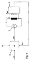
- EBS control device comprises a regulator housing (ECU) with a microcontroller system 18, as shown schematically in FIGS. 1, 2 and 4, and a valve block (HCU) connected to the regulator with electromagnetically operated valves used to control the hydraulic flow 1.
- the controller also includes a drive circuit (current source 3), with which the valve current I can be individually set pulse width modulated for each valve and also measured.
- corresponding valve drivers are provided for each valve, which are realized by means of individually controllable PWM driver stages.
- a measuring device 4 is provided, with which the induction voltage U ind can be measured.
- a signal ⁇ is available which is proportional to the integral over U ind (t).
- I is the coil current
- N is the number of turns of the spool
- RM total of the total magnetic resistance of the magnetic circuit in the valve.
- valve 1 measuring device 4 When switching off the valve current I in Fig. 1, there is a change in the magnetic flux ⁇ in valve 1, which can be measured by the connected to valve 1 measuring device 4 via induction voltage U ind . Measuring device 4 forms the time integral over the course of the induced Voltage U ind and supplies the integrated signal to the microcontroller 18. This signal is proportional to the magnetic flux ⁇ caused by the valve spool.
- An alternative measuring device for determining this integral is described below in connection with FIG. 9.
- valve current flowing through valve spool 1 forms therein the actual control value of the control.
- the pressure gradient G to be set is predetermined by the ABS / ESP control within the computing unit ⁇ C (EBS control unit).
- the differential pressure is known to the arithmetic unit. Depending on the features of the brake control device this is completely sensory or partially determined by a pressure model in a known manner.
- the spring force, the maximum ram stroke and the dependence of the magnetic flux on the valve current are determined once or at different times according to the measuring routine described below (recalibration). Thus, all acting forces and the calculated force / displacement function of the valve stem are known; it is possible to calculate the valve current required for the required pressure gradient.
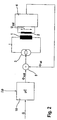
- FIG. 2 shows another possibility for realizing the invention with an additional coil control loop.
- the required pressure gradient G is likewise present in the arithmetic unit (.mu.C).
- the differential pressure is known to the arithmetic unit.
- the spring force and the maximum ram stroke are determined via the measuring routine described below.
- the magnetic flux is detected with a measuring coil 2.
- the measuring coil is arranged to detect the effective magnetic flux through yoke and armature.
- a voltage U ind is induced in the measuring coil whose integral is proportional to the existing magnetic flux.
- the signal ⁇ is which is derived from the signal generated by step 4 integral value, it is intended in differentiating stage 5 with the signal ⁇ together and forms the setpoint variable for the valve driver.
- the measuring routine for determining the valve-specific parameters can be repeated at any time, even during vehicle operation (recalibration), for example to compensate for operational changes or wear of the mechanical or even the electrical components.
- the electronic control increases the coil current via driver 3 until the magnetic flux in the magnetic circuit corresponds to the calculated flux.
- FIG. 2 it is a ram force control in which the ram position depends on the pressure conditions at the valve.
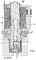
- Fig. 3 shows the structure of a present invention usable solenoid valve in an ABS / ESP valve block.
- the valve according to the examples according to the invention is a normally open valve, which is operated in a manner known per se by means of a PWM-regulated current.
- Corresponding valves are under the name analogized digital valves "AD valve" known.
- the construction of such an SO-AD valve, in particular the components of the magnetic circuit guiding the field lines, will be described in more detail below.
- the energized valve coil 6 serves to move the axially guided in the valve housing 13 armature 7, which engages sealingly via plunger 8 in the valve seat 9. Hydraulic fluid flows via valve inlet 10 to the valve seat 9 and escapes via outlet 12.
- Spring 11 pushes the plunger and armature into the open position, provided that no current flows through coil 6.
- coil 6 penetrate the magnetic field lines yoke 14 and penetrate into the housing 13 a.
- the transition point between the yoke 14 and the housing 13 forms the magnetic resistance RM LR2 .
- the field lines penetrate the air gap 15 between the armature 7 and the housing 13, wherein the magnetic resistance present at this location is designated by RM A.
- armature 7 and yoke 14 there is a further air gap, which is associated with the magnetic resistance RM LR1 .
- the size RM valve can be measured in the closed state and the size RM air results from the formula l ⁇ 0 * A At ker .
- a anchor is the specific for the valve series magnetically effective area of the armature 7 (model-specific characteristic KG all ) and 1 is the ram stroke.
- the actual measuring method does not determine the value for RM air directly but via a measurement of the magnetic resistance when the valve is fully open and subtracting the magnetic resistance of the closed valve. In this way, the ram stroke 1 can be determined.
- FIG. 3 also shows the measuring coil 2 required for carrying out the exemplary embodiment described in FIG. 2, which is positioned in the region of the yoke 14.
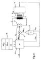
- Fig. 4 schematically illustrates another example of a control loop in which the plunger position 1 is controlled directly.
- the total magnetic resistance RM is composed of the magnetic resistance of the closed valve and the magnetic resistance of the air gap.
- the magnetic resistance of the closed valve can be determined by a unique measuring routine.
- the output of divider 17 is connected to differentiator 5.
- the current differential pressure needed.
- the current valve current is determined and multiplied by the number of turns of the exciter coil.
- the product is the flooding ⁇ (magnetic tension).
- the current magnetic voltage is divided by the current magnetic flux.
- the result is the current magnetic resistance.
- a setpoint / actual value comparison is carried out and the manipulated variable I (coil current) is generated from this.
- the method according to the example in FIG. 4 also offers the possibility of determining the pressure in the fluid lines connected to the valve without additional pressure sensors in the individual pressure sensors.
- the pressure can be calculated analogously to the method described above from the currently measured at this plunger position ram force in conjunction with the known general characteristics KG all of the valve.
- the input pressure is determined, for example, by the brake pedal operation.
- the input pressure deviates from the pressure in the individual hydraulic lines leading to the brake cylinders. Since, in principle, only the differential pressure prevailing at the valve can be determined according to the preceding measurement method, it may be necessary to determine the admission pressure by sensor (for example pressure sensor on the tandem master cylinder). However, the form can also be calculated by model considerations. Furthermore, it is possible, by considering certain operating conditions of the brake system to determine the pressure without precise knowledge of the form. In this way, a completely pressure sensorless pressure determination can be realized. This saves considerable costs for additional pressure sensors in an ABS / ESP brake control unit.
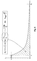
- FIG. 5 shows the current flow in a valve spool after switching off the flow at a closed valve.
- the magnetic resistance RM ges with a known coil turns N can be determined from the integral of the power curve.
- the physical relationship results from the formulas given in the box of FIG. 5, where W L is the magnetic energy of the magnetic circuit and R is the ohmic resistance of the electrical coil circuit.
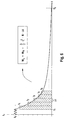
- FIG. 6 An example for carrying out a measuring method for determining the magnetic resistance according to the principle in FIG. 5 is sketched in FIG. 6.
- a current value I 0 is set by the EBS control unit (regulated), in which the valve is securely closed.
- the duty cycle of the PWM control is set so that no more power is fed into the coil driver.
- the current stored by the inductor sounds through the Rezirkulations Kunststoffkeit the output stage.
- the current is first successively increased, starting from a suitably small current of, for example, I ⁇ 0, the stepwise increase.
- the current is initially maintained at a value I 1 at which the valve is just opened, ie at a higher current, the valve would close.
- the current is switched off and the time ⁇ 1 is measured until the current current value has fallen below a threshold value S (time t 2 ). Due to the open position of the valve results in a low inductance and thus a short time constant ⁇ 1 in the exponential Stromabkling .
- sub-image b the current waveform is shown when the corresponding valve is driven with a current I 2 , which causes a closing of the valve.
- the closing process can be seen on a short-term survey 71 of the current in the constant current range.
- the current is switched off as above, the current again sounds below the threshold S from.
- the time constant ⁇ 2 of the initially closed valve is higher due to the lower magnetic resistance (higher inductance) in sub-image b) than the corresponding time constant in sub-image a).
- the opening of the valve which is also recognizable at an elevation 72 in the course of the current, also causes an extension of the time constant.
- FIG. 8 schematically shows an example of an algorithm 82 for calculating the valve opening characteristic curve by means of the valve-specific individual characteristics KG ind (measuring method 81) determined according to the examples in FIGS. 5 to 7 in an electrohydraulic control device 82.
- the valve-specific individual parameters KG ind can generally be characteristic curves or parameters of the valve.
- a curve is needed for a valve control with high accuracy, which indicates the current necessary to open the valve at a predetermined differential pressure ⁇ P (differential pressure-dependent valve opening flow characteristic f ( ⁇ P)).
- KG all which are characteristic of the valve series, are specified on the input side in the controller. These can be designated by the model-specific anchor surface A anchor and the valve sealing A sealing closer. Furthermore, the actual differential pressure .DELTA.P for the relevant valve is specified at the input as a variable variable (Var), which is either determined by the sensor or approximately calculated by the EBS system from other variables.
- Var variable variable
- the current-dependent magnetic force F magn (I) can be calculated.
- the valve In the equilibrium state, the valve is just closed.
- the magnetic force F magn which is necessary for this, gives the holding current:
- F feather + F hydraulic F magn
- the differential pressure-dependent holding current for discrete differential pressures can therefore be calculated relatively accurately taking into account the valve sealing surface and the sealing cross section.
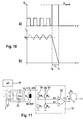
- the exemplary embodiment illustrated in FIG. 9a relates to a circuit arrangement as described in FIG. 1, with the difference that a rectangular shaper 19 shown in FIG. 11 is provided for the simplified measurement of the induction voltage.
- Rectangular former 19 can likewise advantageously be used instead of the measuring device 4 in FIG. 2.
- the EBS regulator comprises a driver circuit 3 (current source) with which the valve current I can be individually set and also pulse-width modulated for each valve.
- the induction voltage U ind in a simple manner over a time measurement, as sketched in part of image b) are measured.
- the magnetic flux in coil 1 of the actuator induces a voltage U L (terminal voltage) when switching off the current at the time t 0 , so that the current drops during the turn-off in a time t c to about the value 0.
- U L terminal voltage
- the voltage curve of U L is shown in detail in Fig. 10a).
- the meanwhile caused by the PWM valve control current profile is shown in Fig. 10b).
- the variables R L (resistance of the coil), U L (regulated Abkommutierwood), and I 0 (valve current) are the arithmetic unit 18 known.
- the time t c which is proportional to the inductance L is, is detected by means of rectangular shaper 19.
- an electrical signal At the output of rectangular shaper 19 is an electrical signal, which is proportional to t c . This signal is supplied via line 20 arithmetic unit 18 as actual size for the control to be made.
- Current source 3 is composed of a current driver 21 and a recirculation circuit 22, which regulates the recirculation current after switching off the current at time t 0 with a controllable resistance, wherein Rezirkulationswan 22 is driven by the arithmetic unit 18.
- a corresponding circuit for driving hydraulic valves is known from the patent application DE 102004017239.0 already known.
- a first voltage divider 51 consisting of resistors R 1 and 9R 1 is connected, which reduces the high voltage values U 0 at the signal input S + of the comparator 53 by about a factor of 10.
- a second voltage divider 52 generates at the input S- of the comparator 53 a reference voltage which is equal to half the logic supply voltage. Comparator 53 thus evaluates the difference of the signals S + and S-, whereby a suitable square-wave signal is generated.
- the current can be commutated after switching off within a relatively short time (less than 1 ms), as shown in Fig. 10b.
- the clamping voltage U L can be set to a constant value U const (FIG. 10 a).
- PWM pulse width modulated control
Landscapes
- Physics & Mathematics (AREA)
- Engineering & Computer Science (AREA)
- Electromagnetism (AREA)
- Fluid Mechanics (AREA)
- Transportation (AREA)
- Mechanical Engineering (AREA)
- Power Engineering (AREA)
- Magnetically Actuated Valves (AREA)
- Regulating Braking Force (AREA)
- Fluid-Pressure Circuits (AREA)
- Control Of Direct Current Motors (AREA)
- Details Of Valves (AREA)
- Power Conversion In General (AREA)
- Flow Control (AREA)
- Control Of Motors That Do Not Use Commutators (AREA)
- Valve Device For Special Equipments (AREA)
Applications Claiming Priority (4)
| Application Number | Priority Date | Filing Date | Title |
|---|---|---|---|
| DE10335586 | 2003-07-31 | ||
| DE10355836 | 2003-11-26 | ||
| DE102004024058 | 2004-05-13 | ||
| EP04766348A EP1651487B1 (fr) | 2003-07-31 | 2004-07-28 | Procede pour determiner le courant d'attaque d'un appareil de reglage |
Related Parent Applications (1)
| Application Number | Title | Priority Date | Filing Date |
|---|---|---|---|
| EP04766348A Division EP1651487B1 (fr) | 2003-07-31 | 2004-07-28 | Procede pour determiner le courant d'attaque d'un appareil de reglage |
Publications (3)
| Publication Number | Publication Date |
|---|---|
| EP1876078A2 true EP1876078A2 (fr) | 2008-01-09 |
| EP1876078A3 EP1876078A3 (fr) | 2009-04-15 |
| EP1876078B1 EP1876078B1 (fr) | 2014-12-17 |
Family
ID=34108295
Family Applications (3)
| Application Number | Title | Priority Date | Filing Date |
|---|---|---|---|
| EP04766345A Expired - Lifetime EP1652197B1 (fr) | 2003-07-31 | 2004-07-28 | Procede pour determiner le flux magnetique dans au moins une electrovanne pouvant etre commandee electriquement par l'intermediaire d'un etage d'excitation |
| EP07019587.0A Expired - Lifetime EP1876078B1 (fr) | 2003-07-31 | 2004-07-28 | Méthode à déterminer le courant dans un actionneur électrique |
| EP04766348A Expired - Lifetime EP1651487B1 (fr) | 2003-07-31 | 2004-07-28 | Procede pour determiner le courant d'attaque d'un appareil de reglage |
Family Applications Before (1)
| Application Number | Title | Priority Date | Filing Date |
|---|---|---|---|
| EP04766345A Expired - Lifetime EP1652197B1 (fr) | 2003-07-31 | 2004-07-28 | Procede pour determiner le flux magnetique dans au moins une electrovanne pouvant etre commandee electriquement par l'intermediaire d'un etage d'excitation |
Family Applications After (1)
| Application Number | Title | Priority Date | Filing Date |
|---|---|---|---|
| EP04766348A Expired - Lifetime EP1651487B1 (fr) | 2003-07-31 | 2004-07-28 | Procede pour determiner le courant d'attaque d'un appareil de reglage |
Country Status (8)
| Country | Link |
|---|---|
| US (2) | US20060209486A1 (fr) |
| EP (3) | EP1652197B1 (fr) |
| JP (2) | JP4889488B2 (fr) |
| KR (1) | KR101166406B1 (fr) |
| AT (1) | ATE380728T1 (fr) |
| DE (4) | DE112004001348D2 (fr) |
| ES (1) | ES2297466T3 (fr) |
| WO (2) | WO2005009815A2 (fr) |
Cited By (3)
| Publication number | Priority date | Publication date | Assignee | Title |
|---|---|---|---|---|
| DE102011080227A1 (de) * | 2011-08-01 | 2013-02-07 | Continental Teves Ag & Co. Ohg | Verfahren zur Optimierung der Druckstellgenauigkeit |
| DE102016200118A1 (de) | 2016-01-08 | 2017-07-13 | Continental Teves Ag & Co. Ohg | Verfahren zur Bestimmung des Öffnungsstromes eines analog angesteuerten Ventils und Druckregelvorrichtung |
| US11667272B2 (en) | 2019-01-24 | 2023-06-06 | ZF Active Safety US Inc. | Vehicle brake system with adaptive pressure calibration |
Families Citing this family (35)
| Publication number | Priority date | Publication date | Assignee | Title |
|---|---|---|---|---|
| JP4552720B2 (ja) * | 2005-03-25 | 2010-09-29 | 株式会社アドヴィックス | 車両用ブレーキ液圧制御装置 |
| KR101068909B1 (ko) | 2005-06-17 | 2011-09-30 | 주식회사 만도 | 솔레노이드밸브의 제어회로 |
| DE102005049300A1 (de) | 2005-10-12 | 2007-04-26 | Continental Teves Ag & Co. Ohg | Verfahren zur Bestimmung des Raddrucks in einem elektronisch ansteuerbaren Kraftfahrzeugbremsenregelungssystem |
| DE102005051937A1 (de) * | 2005-10-29 | 2007-05-03 | Pierburg Gmbh | Schubumluftventilvorrichtung für eine Brennkraftmaschine |
| US7513482B2 (en) * | 2005-11-11 | 2009-04-07 | Advics Co., Ltd. | Actuator for controlling brake hydraulic pressure and solenoid valve thereof |
| DE102007015265B4 (de) * | 2006-03-28 | 2021-01-07 | Continental Teves Ag & Co. Ohg | Verfahren zur Ermittlung der Öffnungsstrom-Charakteristik von analog angesteuerten Ventilen |
| WO2007131947A1 (fr) * | 2006-05-17 | 2007-11-22 | Continental Teves Ag & Co. Ohg | Procédé et circuit de réglage de courant à modulation de largeur d'impulsion pour la commande de charges inductives dans des véhicules automobiles |
| DE102006057501A1 (de) * | 2006-05-19 | 2007-11-22 | Continental Teves Ag & Co. Ohg | Verfahren zur Kalibrierung von analog angesteuerten hydraulischen Einlassventilen |
| DE102006055767B4 (de) * | 2006-06-13 | 2015-10-01 | Continental Teves Ag & Co. Ohg | Verfahren zur Kalibrierung von analog angesteuerten hydraulischen Ventilen |
| DE102006045353A1 (de) * | 2006-09-26 | 2008-04-03 | Lucas Automotive Gmbh | Regeleinheit und Verfahren zur Regelung einer elektromagnetischen Ventilanordnung |
| US7667999B2 (en) * | 2007-03-27 | 2010-02-23 | Sandisk 3D Llc | Method to program a memory cell comprising a carbon nanotube fabric and a steering element |
| DE102007019929A1 (de) * | 2007-04-27 | 2008-11-06 | Continental Teves Ag & Co. Ohg | Korrekturverfahren zum Korrigieren von Ansteuerkennlinien für analogisierte Hydraulikventile in Kraftfahrzeugbremssystemen |
| DE102007032950A1 (de) * | 2007-07-14 | 2009-01-15 | Continental Teves Ag & Co. Ohg | Verfahren zum Bemessen des Vordrucks an einem analogisierten, elektromagnetisch angesteuerten Hydraulikventil |
| DE102007032949B4 (de) * | 2007-07-14 | 2019-04-25 | Continental Teves Ag & Co. Ohg | Verfahren zur Bestimmung der Förderleistung oder der Betätigungshäufigkeit einer Fluidpumpe, insbesondere in einem elektronischen Kraftfahrzeugbremssystem |
| CN100564898C (zh) * | 2007-11-28 | 2009-12-02 | 三一重工股份有限公司 | 电液比例流量阀调速控制系统和方法 |
| DE102008006653A1 (de) * | 2008-01-30 | 2009-08-06 | Continental Teves Ag & Co. Ohg | Verfahren zur Konditionierung eines Regelventils |
| JP5276656B2 (ja) * | 2008-05-23 | 2013-08-28 | ボッシュ株式会社 | 内部パラメータの自動キャリブレーション機能付きの車両用abs制御装置 |
| US8386083B2 (en) * | 2008-06-16 | 2013-02-26 | Mks Instruments, Inc. | Systems and methods for updating valve cracking current in mass flow controllers |
| US9248816B2 (en) | 2012-02-07 | 2016-02-02 | Robert Bosch Gmbh | Hydraulic unit with variable damping |
| DE102013203589A1 (de) * | 2012-03-06 | 2013-09-12 | Continental Teves Ag & Co. Ohg | Verfahren zum Betreiben einer Bremsanlage sowie Bremsanlage |
| JP5680010B2 (ja) * | 2012-03-21 | 2015-03-04 | 株式会社アドヴィックス | 車両用制動装置 |
| JP6027395B2 (ja) * | 2012-10-29 | 2016-11-16 | 株式会社堀場エステック | 流体制御装置 |
| DE102013224662A1 (de) | 2013-12-02 | 2015-06-03 | Siemens Aktiengesellschaft | Elektromagnetischer Aktuator |
| CN104929838B (zh) * | 2014-03-20 | 2018-07-17 | 通用汽车环球科技运作有限责任公司 | 致动器中的参数估计 |
| DE102015104010B4 (de) | 2014-03-20 | 2022-05-05 | GM Global Technology Operations LLC (n. d. Gesetzen des Staates Delaware) | Elektromagnetisches kraftstoffeinspritzventil mit integriertem flusssensor |
| US9777660B2 (en) * | 2014-03-20 | 2017-10-03 | GM Global Technology Operations LLC | Parameter estimation in an actuator |
| DE102014226505A1 (de) | 2014-12-18 | 2016-06-23 | Robert Bosch Gmbh | Elektrische Bestimmung von Kenngrößen magnetischer Schaltventile |
| US9581674B2 (en) | 2015-07-30 | 2017-02-28 | Hamilton Sundstrand Corporation | Dynamic calibrating current sensor |
| DE102015219673B4 (de) * | 2015-10-12 | 2025-08-07 | Schaeffler Technologies AG & Co. KG | Erkennen eines vorbestimmten Öffnungszustandes eines einen Magnetspulenantrieb aufweisenden Kraftstoffinjektors |
| KR101769781B1 (ko) | 2016-04-01 | 2017-08-22 | 주식회사 인팩 | 액추에이터의 구동축 동심도 검출방법 |
| CN108918971B (zh) * | 2018-03-29 | 2022-04-19 | 浙江长兴笛卡尔科技有限公司 | 计算动态等效内阻的方法及装置 |
| DE102018217352B4 (de) * | 2018-10-10 | 2025-02-06 | Vitesco Technologies Germany Gmbh | Aktorvorrichtung sowie Verfahren zur Kompensation eines magnetischen Streufeldes bei einer Aktorvorrichtung |
| KR102307365B1 (ko) * | 2020-07-21 | 2021-10-01 | (주)현대케피코 | 공기 차단 밸브 제어 방법 |
| DE102022201506A1 (de) | 2022-02-14 | 2023-08-17 | Robert Bosch Gesellschaft mit beschränkter Haftung | Verfahren zum stetigen Ausschwenken einer hydraulischen Pumpe |
| CN121866454A (zh) * | 2023-09-18 | 2026-04-14 | 胡斯可国际股份有限公司 | 用于液压控制系统电液设备校准的系统及方法 |
Family Cites Families (22)
| Publication number | Priority date | Publication date | Assignee | Title |
|---|---|---|---|---|
| JPS5872784A (ja) * | 1981-10-26 | 1983-04-30 | Matsushita Electric Ind Co Ltd | 自己保持型電磁弁の制御装置 |
| US4450427A (en) * | 1981-12-21 | 1984-05-22 | General Electric Company | Contactor with flux sensor |
| US4855675A (en) * | 1984-05-21 | 1989-08-08 | Sacol Powerline Limited | Inductive transducers for indicating establishment of a preselected spatial relationship between two parts |
| US4665348A (en) * | 1984-08-09 | 1987-05-12 | Synektron Corporation | Method for sensing and controlling the position of a variable reluctance actuator |
| DE3730523A1 (de) * | 1987-09-11 | 1989-03-30 | Bosch Gmbh Robert | Verfahren und einrichtung zur detektion der schaltzeiten von magnetventilen |
| DE3807278C2 (de) * | 1988-03-05 | 1996-05-23 | Tech Ueberwachungs Verein Rhei | Verfahren zur sicherheitstechnischen Überprüfung von Magnetventilen und Meßanordnung zur Durchführung des Verfahrens |
| US5193568A (en) * | 1991-06-20 | 1993-03-16 | Martin Marietta Energy Systems, Inc. | Noninvasive valve monitor using alternating electromagnetic field |
| JPH07110077A (ja) * | 1993-10-08 | 1995-04-25 | Mikuni Corp | 流量制御リニアソレノイドバルブ及びその駆動回路 |
| DE4440531C2 (de) * | 1993-11-18 | 2003-04-30 | Volkswagen Ag | Verfahren zur größenmäßigen Ermittlung von Hydraulikdrücken in einer blockiergeschützten Kfz-Bremsanlage |
| US5551770A (en) * | 1994-10-27 | 1996-09-03 | Ford Motor Company | Method for estimating pressure in a pressure actuated controller |
| DE19508329A1 (de) * | 1995-03-09 | 1996-09-12 | Teves Gmbh Alfred | Bremsdruckregelanlage |
| DE19529433A1 (de) * | 1995-08-10 | 1997-02-13 | Teves Gmbh Alfred | Verfahren und Schaltungsanordnung zur Überwachung einer Steuerschaltung |
| JP3127798B2 (ja) * | 1995-10-23 | 2001-01-29 | トヨタ自動車株式会社 | ソレノイドバルブのギャップ測定方法 |
| DE19544207C2 (de) * | 1995-11-28 | 2001-03-01 | Univ Dresden Tech | Verfahren zur modellbasierten Messung und Regelung von Bewegungen an elektromagnetischen Aktoren |
| US6577133B1 (en) * | 1998-07-20 | 2003-06-10 | Kelsey-Hayes Company | Inductive measurement of armature travel within a solenoid valve |
| FR2784712B1 (fr) * | 1998-10-15 | 2001-09-14 | Sagem | Procede et dispositif d'actionnement electromagnetique de soupape |
| US6657847B1 (en) * | 1999-07-13 | 2003-12-02 | Siemens Automotive Corporation | Method of using inductance for determining the position of an armature in an electromagnetic solenoid |
| EP1296865B1 (fr) * | 2000-06-20 | 2004-09-08 | Continental Teves AG & Co. oHG | Procede et systeme asservi de commande d'un systeme de freinage a regulation electronique |
| DE10053607A1 (de) * | 2000-10-28 | 2002-05-02 | Bosch Gmbh Robert | Anordnung und Verfahren zum Bestimmen der Temperatur von Ventilen |
| DE10053606B4 (de) * | 2000-10-28 | 2017-05-04 | Robert Bosch Gmbh | Magnetventilregelung und Verfahren zum Regeln eines Magnetventils |
| JP4803882B2 (ja) * | 2001-01-19 | 2011-10-26 | 本田技研工業株式会社 | 電磁アクチュエータ制御装置 |
| DE10201453A1 (de) * | 2001-09-10 | 2003-05-28 | Knorr Bremse Systeme | Verfahren und Steuersystem zum Betreiben eines Magnetventiles für pneumatische Bremszylinder |
-
2004
- 2004-07-28 WO PCT/EP2004/051639 patent/WO2005009815A2/fr not_active Ceased
- 2004-07-28 US US10/566,616 patent/US20060209486A1/en not_active Abandoned
- 2004-07-28 AT AT04766348T patent/ATE380728T1/de not_active IP Right Cessation
- 2004-07-28 EP EP04766345A patent/EP1652197B1/fr not_active Expired - Lifetime
- 2004-07-28 KR KR1020067002192A patent/KR101166406B1/ko not_active Expired - Fee Related
- 2004-07-28 DE DE112004001348T patent/DE112004001348D2/de not_active Withdrawn - After Issue
- 2004-07-28 DE DE112004001351T patent/DE112004001351D2/de not_active Expired - Fee Related
- 2004-07-28 US US10/566,782 patent/US20070158607A1/en not_active Abandoned
- 2004-07-28 DE DE502004005710T patent/DE502004005710D1/de not_active Expired - Lifetime
- 2004-07-28 JP JP2006521584A patent/JP4889488B2/ja not_active Expired - Fee Related
- 2004-07-28 ES ES04766348T patent/ES2297466T3/es not_active Expired - Lifetime
- 2004-07-28 EP EP07019587.0A patent/EP1876078B1/fr not_active Expired - Lifetime
- 2004-07-28 DE DE502004004149T patent/DE502004004149D1/de not_active Expired - Lifetime
- 2004-07-28 WO PCT/EP2004/051636 patent/WO2005013295A1/fr not_active Ceased
- 2004-07-28 EP EP04766348A patent/EP1651487B1/fr not_active Expired - Lifetime
-
2011
- 2011-03-24 JP JP2011066372A patent/JP5535971B2/ja not_active Expired - Fee Related
Cited By (6)
| Publication number | Priority date | Publication date | Assignee | Title |
|---|---|---|---|---|
| DE102011080227A1 (de) * | 2011-08-01 | 2013-02-07 | Continental Teves Ag & Co. Ohg | Verfahren zur Optimierung der Druckstellgenauigkeit |
| US9545901B2 (en) | 2011-08-01 | 2017-01-17 | Continental Teves Ag & Co. Ohg | Method for optimizing the pressure setting accuracy |
| DE102011080227B4 (de) | 2011-08-01 | 2022-05-25 | Continental Teves Ag & Co. Ohg | Verfahren, Verwendung und Fahrzeugbremsanlage zur Optimierung der Druckstellgenauigkeit |
| DE102016200118A1 (de) | 2016-01-08 | 2017-07-13 | Continental Teves Ag & Co. Ohg | Verfahren zur Bestimmung des Öffnungsstromes eines analog angesteuerten Ventils und Druckregelvorrichtung |
| WO2017118541A1 (fr) | 2016-01-08 | 2017-07-13 | Continental Teves Ag & Co. Ohg | Procédé de détermination du courant d'ouverture d'une soupape à commande analogique et dispositif de régulation de la pression |
| US11667272B2 (en) | 2019-01-24 | 2023-06-06 | ZF Active Safety US Inc. | Vehicle brake system with adaptive pressure calibration |
Also Published As
| Publication number | Publication date |
|---|---|
| US20060209486A1 (en) | 2006-09-21 |
| US20070158607A1 (en) | 2007-07-12 |
| WO2005013295A1 (fr) | 2005-02-10 |
| WO2005009815A3 (fr) | 2006-02-02 |
| JP5535971B2 (ja) | 2014-07-02 |
| EP1652197B1 (fr) | 2007-06-20 |
| EP1876078B1 (fr) | 2014-12-17 |
| KR101166406B1 (ko) | 2012-07-23 |
| EP1876078A3 (fr) | 2009-04-15 |
| EP1652197A1 (fr) | 2006-05-03 |
| ES2297466T3 (es) | 2008-05-01 |
| EP1651487A2 (fr) | 2006-05-03 |
| WO2005009815A2 (fr) | 2005-02-03 |
| JP2011157071A (ja) | 2011-08-18 |
| DE112004001348D2 (de) | 2006-08-10 |
| DE502004005710D1 (de) | 2008-01-24 |
| EP1651487B1 (fr) | 2007-12-12 |
| JP2007500643A (ja) | 2007-01-18 |
| ATE380728T1 (de) | 2007-12-15 |
| KR20060069823A (ko) | 2006-06-22 |
| JP4889488B2 (ja) | 2012-03-07 |
| DE502004004149D1 (de) | 2007-08-02 |
| DE112004001351D2 (de) | 2006-09-21 |
Similar Documents
| Publication | Publication Date | Title |
|---|---|---|
| EP1651487B1 (fr) | Procede pour determiner le courant d'attaque d'un appareil de reglage | |
| DE19654427B4 (de) | Verfahren und Vorrichtung zur Regelung des Drucks in wenigstens einer Radbremse | |
| EP2238001B1 (fr) | Procédé de conditionnement d'une soupape de régulation | |
| EP2152555B1 (fr) | Procédé de correction des caractéristiques de commande de soupapes hydraulique à fonctionnement analogique dans des systèmes de freinage d'automobiles | |
| DE102007010514A1 (de) | Verfahren zur Kalibrierung von analogisierten Ventilen in einer Druckregelvorrichtung | |
| EP1651485B1 (fr) | Procede et dispositif pour produire et/ou ajuster un actionneur pouvant etre commande de maniere electromagnetique | |
| DE102007032949B4 (de) | Verfahren zur Bestimmung der Förderleistung oder der Betätigungshäufigkeit einer Fluidpumpe, insbesondere in einem elektronischen Kraftfahrzeugbremssystem | |
| WO2001098124A1 (fr) | Procede et systeme asservi de commande d'un systeme de freinage a regulation electronique | |
| DE102011080227A1 (de) | Verfahren zur Optimierung der Druckstellgenauigkeit | |
| EP2890594A1 (fr) | Procédé d'inversion de commutation pour une électrovanne à fonctionnement analogique, système de freinage électrohydraulique et utilisation du système de freinage électrohydraulique | |
| EP3612421B1 (fr) | Methode pour determiner les prametres de commutation des soupapes a solenoide d'un systeme de freinage | |
| DE102005056776A1 (de) | Elektromagnetisch ansteuerbares Stellgerät und Verfahren zu dessen Herstellung und/oder Justage | |
| EP1651486B1 (fr) | Procede et dispositif pour mesurer une pression de fluide au moyen d'un organe de regulation | |
| EP1937529B1 (fr) | Procede pour determiner la pression aux roues dans un systeme de regulation de freinage de vehicule automobile a commande electronique | |
| DE10104497B4 (de) | Verfahren zur Steuerung des Druckes in den Radbremsen eines elektronisch geregelten Bremssystems | |
| EP2170667B1 (fr) | Procédé pour mesurer la pression d'alimentation au niveau d'une soupape hydraulique analoguée, à commande électromagnétique | |
| DE10106464A1 (de) | Verfahren und Regelsystem zur Ansteuerung eines elektronisch regelbaren Bremsbetätigungssystems | |
| DE102007018515A1 (de) | Vorrichtung zur Bremsdruckregelung mit Blockierschutzfunktion und weiteren Regelungen | |
| DE19744111C1 (de) | Elektronisch steuerbarer Bremskraftverstärker | |
| DE102011075295A1 (de) | Verfahren zur Kalibrierung eines analog regelnden Hydraulikventils | |
| DE10021436B4 (de) | Verfahren und Einrichtung zum Ermitteln einer Stellgröße eines Ventils und Verfahren und Einrichtung zum Ermitteln einer die Bewegungsgeschwindigkeit eines Aktuators eines Ventils wiedergebenden Größe | |
| DE19937475A1 (de) | Vorrichtung und Verfahren zum Steuern einer hydraulischen Bremsanlage | |
| DE102008029486A1 (de) | Ventileinrichtung |
Legal Events
| Date | Code | Title | Description |
|---|---|---|---|
| PUAI | Public reference made under article 153(3) epc to a published international application that has entered the european phase |
Free format text: ORIGINAL CODE: 0009012 |
|
| AC | Divisional application: reference to earlier application |
Ref document number: 1651487 Country of ref document: EP Kind code of ref document: P |
|
| AK | Designated contracting states |
Kind code of ref document: A2 Designated state(s): AT BE BG CH CY CZ DE DK EE ES FI FR GB GR HU IE IT LI LU MC NL PL PT RO SE SI SK TR |
|
| PUAL | Search report despatched |
Free format text: ORIGINAL CODE: 0009013 |
|
| AK | Designated contracting states |
Kind code of ref document: A3 Designated state(s): AT BE BG CH CY CZ DE DK EE ES FI FR GB GR HU IE IT LI LU MC NL PL PT RO SE SI SK TR |
|
| 17P | Request for examination filed |
Effective date: 20091015 |
|
| AKX | Designation fees paid |
Designated state(s): DE FR |
|
| 17Q | First examination report despatched |
Effective date: 20131112 |
|
| GRAP | Despatch of communication of intention to grant a patent |
Free format text: ORIGINAL CODE: EPIDOSNIGR1 |
|
| INTG | Intention to grant announced |
Effective date: 20140820 |
|
| GRAS | Grant fee paid |
Free format text: ORIGINAL CODE: EPIDOSNIGR3 |
|
| GRAA | (expected) grant |
Free format text: ORIGINAL CODE: 0009210 |
|
| AC | Divisional application: reference to earlier application |
Ref document number: 1651487 Country of ref document: EP Kind code of ref document: P |
|
| AK | Designated contracting states |
Kind code of ref document: B1 Designated state(s): DE FR |
|
| REG | Reference to a national code |
Ref country code: DE Ref legal event code: R096 Ref document number: 502004014789 Country of ref document: DE Effective date: 20150212 |
|
| REG | Reference to a national code |
Ref country code: DE Ref legal event code: R097 Ref document number: 502004014789 Country of ref document: DE |
|
| PLBE | No opposition filed within time limit |
Free format text: ORIGINAL CODE: 0009261 |
|
| STAA | Information on the status of an ep patent application or granted ep patent |
Free format text: STATUS: NO OPPOSITION FILED WITHIN TIME LIMIT |
|
| 26N | No opposition filed |
Effective date: 20150918 |
|
| REG | Reference to a national code |
Ref country code: FR Ref legal event code: PLFP Year of fee payment: 13 |
|
| REG | Reference to a national code |
Ref country code: FR Ref legal event code: PLFP Year of fee payment: 14 |
|
| REG | Reference to a national code |
Ref country code: FR Ref legal event code: PLFP Year of fee payment: 15 |
|
| REG | Reference to a national code |
Ref country code: DE Ref legal event code: R084 Ref document number: 502004014789 Country of ref document: DE |
|
| REG | Reference to a national code |
Ref country code: DE Ref legal event code: R081 Ref document number: 502004014789 Country of ref document: DE Owner name: CONTINENTAL AUTOMOTIVE TECHNOLOGIES GMBH, DE Free format text: FORMER OWNER: CONTINENTAL TEVES AG & CO. OHG, 60488 FRANKFURT, DE |
|
| P01 | Opt-out of the competence of the unified patent court (upc) registered |
Effective date: 20230522 |
|
| PGFP | Annual fee paid to national office [announced via postgrant information from national office to epo] |
Ref country code: FR Payment date: 20230725 Year of fee payment: 20 Ref country code: DE Payment date: 20230731 Year of fee payment: 20 |
|
| REG | Reference to a national code |
Ref country code: DE Ref legal event code: R081 Ref document number: 502004014789 Country of ref document: DE Owner name: CONTINENTAL AUTOMOTIVE TECHNOLOGIES GMBH, DE Free format text: FORMER OWNER: CONTINENTAL AUTOMOTIVE TECHNOLOGIES GMBH, 30165 HANNOVER, DE |
|
| REG | Reference to a national code |
Ref country code: DE Ref legal event code: R071 Ref document number: 502004014789 Country of ref document: DE |