EP1876082A2 - Fahrzeugsteuerungseinheit, Fahrzeugsteuerungsverfahren und Fahrzeug - Google Patents
Fahrzeugsteuerungseinheit, Fahrzeugsteuerungsverfahren und Fahrzeug Download PDFInfo
- Publication number
- EP1876082A2 EP1876082A2 EP07252667A EP07252667A EP1876082A2 EP 1876082 A2 EP1876082 A2 EP 1876082A2 EP 07252667 A EP07252667 A EP 07252667A EP 07252667 A EP07252667 A EP 07252667A EP 1876082 A2 EP1876082 A2 EP 1876082A2
- Authority
- EP
- European Patent Office
- Prior art keywords
- electricity storage
- storage device
- power
- inverter
- brake chopper
- Prior art date
- Legal status (The legal status is an assumption and is not a legal conclusion. Google has not performed a legal analysis and makes no representation as to the accuracy of the status listed.)
- Withdrawn
Links
Images



Classifications
-
- B—PERFORMING OPERATIONS; TRANSPORTING
- B60—VEHICLES IN GENERAL
- B60W—CONJOINT CONTROL OF VEHICLE SUB-UNITS OF DIFFERENT TYPE OR DIFFERENT FUNCTION; CONTROL SYSTEMS SPECIALLY ADAPTED FOR HYBRID VEHICLES; ROAD VEHICLE DRIVE CONTROL SYSTEMS FOR PURPOSES NOT RELATED TO THE CONTROL OF A PARTICULAR SUB-UNIT
- B60W20/00—Control systems specially adapted for hybrid vehicles
- B60W20/10—Controlling the power contribution of each of the prime movers to meet required power demand
- B60W20/13—Controlling the power contribution of each of the prime movers to meet required power demand in order to stay within battery power input or output limits; in order to prevent overcharging or battery depletion
-
- B—PERFORMING OPERATIONS; TRANSPORTING
- B60—VEHICLES IN GENERAL
- B60K—ARRANGEMENT OR MOUNTING OF PROPULSION UNITS OR OF TRANSMISSIONS IN VEHICLES; ARRANGEMENT OR MOUNTING OF PLURAL DIVERSE PRIME-MOVERS IN VEHICLES; AUXILIARY DRIVES FOR VEHICLES; INSTRUMENTATION OR DASHBOARDS FOR VEHICLES; ARRANGEMENTS IN CONNECTION WITH COOLING, AIR INTAKE, GAS EXHAUST OR FUEL SUPPLY OF PROPULSION UNITS IN VEHICLES
- B60K6/00—Arrangement or mounting of plural diverse prime-movers for mutual or common propulsion, e.g. hybrid propulsion systems comprising electric motors and internal combustion engines
- B60K6/20—Arrangement or mounting of plural diverse prime-movers for mutual or common propulsion, e.g. hybrid propulsion systems comprising electric motors and internal combustion engines the prime-movers consisting of electric motors and internal combustion engines, e.g. HEVs
- B60K6/42—Arrangement or mounting of plural diverse prime-movers for mutual or common propulsion, e.g. hybrid propulsion systems comprising electric motors and internal combustion engines the prime-movers consisting of electric motors and internal combustion engines, e.g. HEVs characterised by the architecture of the hybrid electric vehicle
- B60K6/46—Series type
-
- B—PERFORMING OPERATIONS; TRANSPORTING
- B60—VEHICLES IN GENERAL
- B60L—PROPULSION OF ELECTRICALLY-PROPELLED VEHICLES; SUPPLYING ELECTRIC POWER FOR AUXILIARY EQUIPMENT OF ELECTRICALLY-PROPELLED VEHICLES; ELECTRODYNAMIC BRAKE SYSTEMS FOR VEHICLES IN GENERAL; MAGNETIC SUSPENSION OR LEVITATION FOR VEHICLES; MONITORING OPERATING VARIABLES OF ELECTRICALLY-PROPELLED VEHICLES; ELECTRIC SAFETY DEVICES FOR ELECTRICALLY-PROPELLED VEHICLES
- B60L50/00—Electric propulsion with power supplied within the vehicle
- B60L50/50—Electric propulsion with power supplied within the vehicle using propulsion power supplied by batteries or fuel cells
- B60L50/60—Electric propulsion with power supplied within the vehicle using propulsion power supplied by batteries or fuel cells using power supplied by batteries
- B60L50/61—Electric propulsion with power supplied within the vehicle using propulsion power supplied by batteries or fuel cells using power supplied by batteries by batteries charged by engine-driven generators, e.g. series hybrid electric vehicles
-
- B—PERFORMING OPERATIONS; TRANSPORTING
- B60—VEHICLES IN GENERAL
- B60L—PROPULSION OF ELECTRICALLY-PROPELLED VEHICLES; SUPPLYING ELECTRIC POWER FOR AUXILIARY EQUIPMENT OF ELECTRICALLY-PROPELLED VEHICLES; ELECTRODYNAMIC BRAKE SYSTEMS FOR VEHICLES IN GENERAL; MAGNETIC SUSPENSION OR LEVITATION FOR VEHICLES; MONITORING OPERATING VARIABLES OF ELECTRICALLY-PROPELLED VEHICLES; ELECTRIC SAFETY DEVICES FOR ELECTRICALLY-PROPELLED VEHICLES
- B60L7/00—Electrodynamic brake systems for vehicles in general
- B60L7/10—Dynamic electric regenerative braking
- B60L7/14—Dynamic electric regenerative braking for vehicles propelled by AC motors
-
- B—PERFORMING OPERATIONS; TRANSPORTING
- B60—VEHICLES IN GENERAL
- B60L—PROPULSION OF ELECTRICALLY-PROPELLED VEHICLES; SUPPLYING ELECTRIC POWER FOR AUXILIARY EQUIPMENT OF ELECTRICALLY-PROPELLED VEHICLES; ELECTRODYNAMIC BRAKE SYSTEMS FOR VEHICLES IN GENERAL; MAGNETIC SUSPENSION OR LEVITATION FOR VEHICLES; MONITORING OPERATING VARIABLES OF ELECTRICALLY-PROPELLED VEHICLES; ELECTRIC SAFETY DEVICES FOR ELECTRICALLY-PROPELLED VEHICLES
- B60L7/00—Electrodynamic brake systems for vehicles in general
- B60L7/24—Electrodynamic brake systems for vehicles in general with additional mechanical or electromagnetic braking
- B60L7/26—Controlling the braking effect
-
- B—PERFORMING OPERATIONS; TRANSPORTING
- B60—VEHICLES IN GENERAL
- B60W—CONJOINT CONTROL OF VEHICLE SUB-UNITS OF DIFFERENT TYPE OR DIFFERENT FUNCTION; CONTROL SYSTEMS SPECIALLY ADAPTED FOR HYBRID VEHICLES; ROAD VEHICLE DRIVE CONTROL SYSTEMS FOR PURPOSES NOT RELATED TO THE CONTROL OF A PARTICULAR SUB-UNIT
- B60W10/00—Conjoint control of vehicle sub-units of different type or different function
- B60W10/04—Conjoint control of vehicle sub-units of different type or different function including control of propulsion units
- B60W10/08—Conjoint control of vehicle sub-units of different type or different function including control of propulsion units including control of electric propulsion units, e.g. motors or generators
-
- B—PERFORMING OPERATIONS; TRANSPORTING
- B60—VEHICLES IN GENERAL
- B60W—CONJOINT CONTROL OF VEHICLE SUB-UNITS OF DIFFERENT TYPE OR DIFFERENT FUNCTION; CONTROL SYSTEMS SPECIALLY ADAPTED FOR HYBRID VEHICLES; ROAD VEHICLE DRIVE CONTROL SYSTEMS FOR PURPOSES NOT RELATED TO THE CONTROL OF A PARTICULAR SUB-UNIT
- B60W10/00—Conjoint control of vehicle sub-units of different type or different function
- B60W10/24—Conjoint control of vehicle sub-units of different type or different function including control of energy storage means
- B60W10/26—Conjoint control of vehicle sub-units of different type or different function including control of energy storage means for electrical energy, e.g. batteries or capacitors
-
- B—PERFORMING OPERATIONS; TRANSPORTING
- B60—VEHICLES IN GENERAL
- B60W—CONJOINT CONTROL OF VEHICLE SUB-UNITS OF DIFFERENT TYPE OR DIFFERENT FUNCTION; CONTROL SYSTEMS SPECIALLY ADAPTED FOR HYBRID VEHICLES; ROAD VEHICLE DRIVE CONTROL SYSTEMS FOR PURPOSES NOT RELATED TO THE CONTROL OF A PARTICULAR SUB-UNIT
- B60W30/00—Purposes of road vehicle drive control systems not related to the control of a particular sub-unit, e.g. of systems using conjoint control of vehicle sub-units
- B60W30/18—Propelling the vehicle
- B60W30/18009—Propelling the vehicle related to particular drive situations
- B60W30/18109—Braking
- B60W30/18127—Regenerative braking
-
- B—PERFORMING OPERATIONS; TRANSPORTING
- B60—VEHICLES IN GENERAL
- B60L—PROPULSION OF ELECTRICALLY-PROPELLED VEHICLES; SUPPLYING ELECTRIC POWER FOR AUXILIARY EQUIPMENT OF ELECTRICALLY-PROPELLED VEHICLES; ELECTRODYNAMIC BRAKE SYSTEMS FOR VEHICLES IN GENERAL; MAGNETIC SUSPENSION OR LEVITATION FOR VEHICLES; MONITORING OPERATING VARIABLES OF ELECTRICALLY-PROPELLED VEHICLES; ELECTRIC SAFETY DEVICES FOR ELECTRICALLY-PROPELLED VEHICLES
- B60L2200/00—Type of vehicles
- B60L2200/26—Rail vehicles
-
- B—PERFORMING OPERATIONS; TRANSPORTING
- B60—VEHICLES IN GENERAL
- B60L—PROPULSION OF ELECTRICALLY-PROPELLED VEHICLES; SUPPLYING ELECTRIC POWER FOR AUXILIARY EQUIPMENT OF ELECTRICALLY-PROPELLED VEHICLES; ELECTRODYNAMIC BRAKE SYSTEMS FOR VEHICLES IN GENERAL; MAGNETIC SUSPENSION OR LEVITATION FOR VEHICLES; MONITORING OPERATING VARIABLES OF ELECTRICALLY-PROPELLED VEHICLES; ELECTRIC SAFETY DEVICES FOR ELECTRICALLY-PROPELLED VEHICLES
- B60L2210/00—Converter types
- B60L2210/20—AC to AC converters
-
- B—PERFORMING OPERATIONS; TRANSPORTING
- B60—VEHICLES IN GENERAL
- B60W—CONJOINT CONTROL OF VEHICLE SUB-UNITS OF DIFFERENT TYPE OR DIFFERENT FUNCTION; CONTROL SYSTEMS SPECIALLY ADAPTED FOR HYBRID VEHICLES; ROAD VEHICLE DRIVE CONTROL SYSTEMS FOR PURPOSES NOT RELATED TO THE CONTROL OF A PARTICULAR SUB-UNIT
- B60W20/00—Control systems specially adapted for hybrid vehicles
-
- B—PERFORMING OPERATIONS; TRANSPORTING
- B60—VEHICLES IN GENERAL
- B60W—CONJOINT CONTROL OF VEHICLE SUB-UNITS OF DIFFERENT TYPE OR DIFFERENT FUNCTION; CONTROL SYSTEMS SPECIALLY ADAPTED FOR HYBRID VEHICLES; ROAD VEHICLE DRIVE CONTROL SYSTEMS FOR PURPOSES NOT RELATED TO THE CONTROL OF A PARTICULAR SUB-UNIT
- B60W2510/00—Input parameters relating to a particular sub-units
- B60W2510/24—Energy storage means
- B60W2510/242—Energy storage means for electrical energy
- B60W2510/244—Charge state
-
- Y—GENERAL TAGGING OF NEW TECHNOLOGICAL DEVELOPMENTS; GENERAL TAGGING OF CROSS-SECTIONAL TECHNOLOGIES SPANNING OVER SEVERAL SECTIONS OF THE IPC; TECHNICAL SUBJECTS COVERED BY FORMER USPC CROSS-REFERENCE ART COLLECTIONS [XRACs] AND DIGESTS
- Y02—TECHNOLOGIES OR APPLICATIONS FOR MITIGATION OR ADAPTATION AGAINST CLIMATE CHANGE
- Y02T—CLIMATE CHANGE MITIGATION TECHNOLOGIES RELATED TO TRANSPORTATION
- Y02T10/00—Road transport of goods or passengers
- Y02T10/60—Other road transportation technologies with climate change mitigation effect
- Y02T10/62—Hybrid vehicles
-
- Y—GENERAL TAGGING OF NEW TECHNOLOGICAL DEVELOPMENTS; GENERAL TAGGING OF CROSS-SECTIONAL TECHNOLOGIES SPANNING OVER SEVERAL SECTIONS OF THE IPC; TECHNICAL SUBJECTS COVERED BY FORMER USPC CROSS-REFERENCE ART COLLECTIONS [XRACs] AND DIGESTS
- Y02—TECHNOLOGIES OR APPLICATIONS FOR MITIGATION OR ADAPTATION AGAINST CLIMATE CHANGE
- Y02T—CLIMATE CHANGE MITIGATION TECHNOLOGIES RELATED TO TRANSPORTATION
- Y02T10/00—Road transport of goods or passengers
- Y02T10/60—Other road transportation technologies with climate change mitigation effect
- Y02T10/70—Energy storage systems for electromobility, e.g. batteries
-
- Y—GENERAL TAGGING OF NEW TECHNOLOGICAL DEVELOPMENTS; GENERAL TAGGING OF CROSS-SECTIONAL TECHNOLOGIES SPANNING OVER SEVERAL SECTIONS OF THE IPC; TECHNICAL SUBJECTS COVERED BY FORMER USPC CROSS-REFERENCE ART COLLECTIONS [XRACs] AND DIGESTS
- Y02—TECHNOLOGIES OR APPLICATIONS FOR MITIGATION OR ADAPTATION AGAINST CLIMATE CHANGE
- Y02T—CLIMATE CHANGE MITIGATION TECHNOLOGIES RELATED TO TRANSPORTATION
- Y02T10/00—Road transport of goods or passengers
- Y02T10/60—Other road transportation technologies with climate change mitigation effect
- Y02T10/72—Electric energy management in electromobility
Definitions
- the present invention relates to a vehicle control unit suitable for controlling a vehicle, a vehicle provided with the vehicle control unit, and a vehicle control method.
- the vehicle speed is decreased by a braking method using a brake system or a method using an electrical brake (regenerative brake) in which the motor is used as a generator.
- the electrical brake the generated electric power (regenerative power) is charged in an energy storage device such as a capacitor, and thereby the loss of energy can be reduced. Thereby, the regenerative energy obtained at the time of braking can be utilized effectively.
- Japanese Patent Laid-Open No. 2003-134604 discloses an example of a vehicle in which the regenerative energy generated when a railway vehicle is braked by a regenerative brake is stored in a electricity storage device such as a battery and utilized effectively, by which the railway vehicle is operated with high efficiency.
- An object of the present invention is to provide a vehicle control unit, and a vehicle, which can realize an efficient operation utilizing regenerative energy and achieve reduced maintenance and low cost.
- a vehicle control unit in accordance with the present invention includes an ac motor for driving a vehicle, an inverter for converting a direct current into an alternating current of variable voltage and variable frequency to drive the ac motor, a brake chopper formed by a series circuit consisting of a resistor and a switching element connected to the direct current side of the inverter, and an electricity storage device connected to the direct current side of the inverter. Also, a vehicle in accordance with the present invention is mounted with the above-described vehicle control unit.
- the regenerative energy generated at the time of braking can be stored in the electricity storage device. Also, in the case where the electricity storage amount of the electricity storage device exceeds the upper limit, the regenerative energy can be consumed by the brake chopper, so that a mechanical brake need not be used.
- the regenerative energy generated at the time of braking is stored in the electricity storage device, and can be utilized effectively by being consumed when power runs short, for example, during acceleration or during vehicle stop, so that an efficient operation can be realized. Also, even in the case where the electricity storage amount of the electricity storage device exceeds the upper limit, the regenerative energy can be consumed by the brake chopper, so that a mechanical brake need not be used. Therefore, brake shoes etc. can be prevented from being worn, by which the maintenance can be reduced. Further, the capacity of the electricity storage device need not be increased excessively, so that a low-cost and lightweight vehicle control unit and a vehicle provided with the vehicle control unit can be realized.
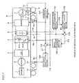
- FIG. 1 shows an example of the general configuration in accordance with the first embodiment of the present invention.
- This example is configured so that an engine 1, a generator 2 connected to the engine 1, and an AC/DC converter 3 for converting the generated electric power into a direct current are connected in series, and on the direct current side of the AC/DC converter 3, a brake chopper 4, an electricity storage device 5, and an inverter 6 are connected in parallel.
- the brake chopper 4 is formed by a series circuit consisting of a resistor 401 and a switching element 402.
- the electricity storage device 5 consists of a chargeable and dischargeable battery such as a lithium-ion battery.
- the inverter 6 is connected with an ac motor 7.
- wheels 8 are driven to run a vehicle 9.
- the wheel 8 is provided with a mechanical brake 10, and the ac motor 7 is provided with a speed sensor 11.
- an inverter control section 101 for controlling the inverter 6, a mechanical brake control section 103 for controlling the mechanical brake 10, an electricity storage amount control section 105 for controlling the electricity storage amount of the electricity storage device 5, and a brake chopper control section 107 for controlling the brake chopper 4 to carry out the control of each of the devices.
- the generator 2 when the vehicle is accelerated, the generator 2 is driven by the engine 1, and the generated electric power is converted into a direct current by the AC/DC converter 3.
- the dc power converted by the AC/DC converter 3 is transmitted to the inverter 6.
- the direct current is converted into an alternating current to drive the ac motor 7, by which the wheels 8 are driven to run the vehicle 9.
- the ac motor 7 is operated as a generator to apply brake.
- the power generated by the ac motor 7 is input to the inverter 6, and in the inverter 6, the power is converted into a dc power and is stored in the electricity storage device 5.
- the inverter control section 101 receives the speed Vt of the ac motor 7, which is detected by the speed sensor 11, and a first torque command Tref, and sends a second torque command T*.
- the first torque command Tref is a command sent from a host controller according to the notch signal of driver's cab and the speed.
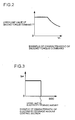
- FIG. 2 shows a characteristic of the upper limit value of the second torque command T*.
- the inverter control section 101 determines the upper limit value of the second torque command T* using the speed Vt of the ac motor 7 and the characteristic shown in FIG. 2, limits the first torque command Tref by the determined upper limit value of the second torque command, and outputs the value as the second torque command T*.
- the inverter 6 converts the direct current into an alternating current of variable frequency and variable voltage to drive the ac motor 7 so that the second torque command T* sent from the inverter control section 101 and the output torque of the ac motor 7 coincide with each other.
- the mechanical brake control section 103 is configured so as to receive the output of a subtracter 102.
- the subtracter 102 receives the first torque command Tref sent from the host controller and the second torque command T* sent from the inverter control section 101, and subtracts the second torque command T* from the first torque command Tref to determine a torque difference ⁇ T.
- the mechanical brake control section 103 carries out control so that the torque difference ⁇ T sent form the subtracter 102 and the braking force of the mechanical brake 10 coincide with each other.
- an electricity storage device observing section 104 receives an electricity storage device voltage Vb and an electricity storage device current Ib of the electricity storage device 5, and estimates an electricity storage amount SOC.
- the electricity storage amount control section 105 receives the electricity storage amount SOC sent from the electricity storage device observing section 104, and sends an electricity storage device current command Ib* based on the electricity storage amount SOC.
- FIG. 3 shows the relationship between the electricity storage amount SOC and the electricity storage device current command Ib* sent from the electricity storage amount control section 105.
- the electricity storage device current command Ib* is a rated current, and in the case where it exceeds the electricity storage amount upper limit, the electricity storage device current command Ib* is zero.
- the electricity storage device current command Ib* sent from the electricity storage amount control section 105 is fed into a subtracter 106.
- the subtracter 106 receives the electricity storage device current command Ib* and the electricity storage device current Ib, and subtracts the electricity storage device current Ib from the electricity storage device current command Ib* to output an electricity storage device current difference ⁇ Ib.
- the brake chopper 4 receives the conduction ratio VBr sent from the brake chopper control section 107, performs switching of the switching element 402 based on the conduction ratio VBr, and consumes electric power in the resistor 401.
- the brake chopper 4 By controlling the electricity storage amount control section 105 and the brake chopper control section 107 in association with each other in this manner, in the brake chopper 4, an excess of regenerative power can be consumed so as not to exceed the electricity storage amount upper limit of the electricity storage device 5.
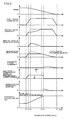
- FIG. 4 shows one example of the operation at the braking time in accordance with the first embodiment of the present invention.
- the abscissa represents time, and the ordinate represents, from the upside, the speed of the vehicle 9, the first torque command Tref, the second torque command T*, the braking force of mechanical brake, the power of regenerative brake, the power of mechanical brake, the electricity storage device current Ib and the electricity storage device current command Ib*, the conduction ratio VBr of brake chopper, and the electricity storage amount SOC.
- the vehicle 9 is running, and the electricity storage amount SOC takes a value smaller than the electricity storage amount upper limit.
- the first torque command Tref rises, and the braking of the vehicle 9 starts.
- the second torque command T* also rises, so that the decrease amount of kinetic energy of the vehicle 9 is made regenerative brake power by the regenerative brake. Since the regenerative brake power flows into the electricity storage device 5 via the inverter 6, the electricity storage device current Ib increases, and the electricity storage amount SOC increases.
- the second torque command T* is limited by the upper limit value.
- the torque difference ⁇ T increases, so that the braking force of mechanical brake is generated.
- the first torque command Tref becomes constant, and subsequently, as the speed decreases, the second torque command T* increases. Thereby, the braking force of mechanical brake is decreased, and at time T4, the braking force of mechanical brake becomes zero.
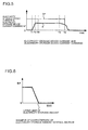
- FIG. 5 is a graph enlargedly showing the state of the electricity storage device current Ib and the electricity storage device current command Ib* near time T5. After the electricity storage device current command Ib* has become zero in this manner, the current flows to the brake chopper 4 side, by which the electricity storage device current Ib is decreased.
- the electricity storage amount SOC of the electricity storage device 5 reaches the electricity storage amount upper limit, braking can be performed without the use of the mechanical brake, so that the wear of the mechanical brake can be restrained. Also, if the conduction ratio VBr increases, control is carried out so that the electricity storage device current Ib decreases and coincides with the electricity storage device current command Ib*. Therefore, the electricity storage amount SOC also does not exceed the electricity storage amount upper limit.
- the conduction ratio VBr decreases so that the electricity storage device current Ib coincides with the electricity storage device current command Ib*, and the current of the brake chopper 4 also decreases. Therefore, the power stored in the electricity storage device is not consumed by the brake chopper 4.
- the vehicle 9 stops at time T6 the first torque command Tref becomes zero, and the regenerative brake power also becomes zero, so that the conduction ratio VBr also becomes zero.
- the electricity storage amount control section 105 may have a characteristic such that the electricity storage device current command Ib* is decreased gradually with respect to the electricity storage amount SOC so that the electricity storage device current command Ib* becomes zero at the electricity storage amount upper limit as shown in FIG. 6.
- the electricity storage device current command Ib* decreases from the state in which the electricity storage amount SOC is smaller than the electricity storage amount upper limit, and the electricity storage device current Ib also decreases, so that the electricity storage amount SOC is less prone to exceed the electricity storage amount upper limit.
- the regenerative energy caused by the regenerative brake is stored in the electricity storage device 5, by which the regenerative energy can be utilized effectively. Also, even in the case where regenerative energy exceeding the electricity storage amount upper limit of the electricity storage device 5, the regenerative power can be treated by the low-cost brake chopper, so that the mechanical brake need not be used, and the maintenance can be reduced.
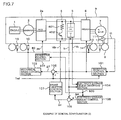
- FIG. 7 shows an example of the general configuration in accordance with the second embodiment.
- the same reference numerals are applied to the same elements as those shown in FIG. 1 explained in the first embodiment, and the detailed explanation thereof is omitted.
- an AC/DC converter 3a is connected to the generator 2, and a converter control section 201 for controlling the AC/DC converter 3a is provided.
- the brake chopper 4 On the direct current side of the AC/DC converter 3a, the brake chopper 4, the electricity storage device 5, and the inverter 6 are connected in parallel.
- the converter control section 201 operates a converter output command P* so that power flows from the direct current side to the alternating current side when the electricity storage amount SOC exceeds the electricity storage amount upper limit in a braked state to control the AC/DC converter 3a.
- the AC/DC converter 3a converts the alternating current of variable voltage and variable frequency on the generator 2 side and the direct current on the inverter 6 side bidirectionally according to the converter output command P* which is the output of the converter control section 201. That is to say, when the electricity storage amount SOC exceeds the electricity storage amount upper limit in a braked state, the generator 2 is controlled so that electrical energy is converted into mechanical energy, and a state in which the vehicle 9 is braked by the engine brake is formed. At this time, the regenerative energy produced by the ac motor 7 is consumed by the engine 1 via the inverter 6, the AC/DC converter 3a, and the generator 2.
- FIG. 8 shows one example of the operation in accordance with the second embodiment of the present invention.
- the explanation of the same portions as those in one example of the operation shown in FIG. 4 explained in the first embodiment is omitted.
- the chart that is the sixth from the upside in FIG. 4 shows the change in the mechanical brake power
- the chart that is the sixth from the upside in FIG. 8 shows the change in the converter output command P*.
- the converter output command P* is zero, and the operations of other portions are the same as the operations shown in FIG. 4.
- a brake chopper conduction ratio command VBr is increased by the electricity storage device current difference ⁇ Ib, which is a difference between the electricity storage device current command Ib* and the electricity storage device current Ib.
- ⁇ Ib is a difference between the electricity storage device current command Ib* and the electricity storage device current Ib.
- some of regenerative brake power is consumed by the engine 1 via the AC/DC converter 3a and the generator 2, so that the electricity storage device current Ib decreases as compared with the first embodiment, and the brake chopper conduction ratio command VBr also takes a smaller value than in the first embodiment.
- the energy consumed by the brake chopper 4 is decreased as compared with the first embodiment, so that the capacity of the brake chopper can be decreased.
- the regenerative power can be utilized effectively by storing the regenerative power caused by the regenerative brake in the electricity storage device 5, even in the case where the regenerative energy exceeding the electricity storage amount upper limit of the electricity storage device 5 is produced, the regenerative power can be treated by the low-cost brake chopper, and the maintenance can be reduced because the mechanical brake need not be used.
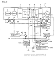
- FIG. 9 shows an example of the general configuration in accordance with the third embodiment.
- the same reference numerals are applied to the same elements as those shown in FIG. 1 explained in the first embodiment, and the detailed explanation thereof is omitted.
- a current detector 301 for detecting an inverter direct current which is the dc side current of the inverter 6, and an inverter power calculating section 302.
- the inverter power calculating section 302 calculates inverter power Pi from the product of the inverter direct current detected by the current detector 301 times the electricity storage device voltage Vb.
- the sign of the inverter power Pi is made positive.
- An electricity storage amount control section 105a sends chargeable power Pb* based on the electricity storage amount SOC fed from the electricity storage device observing section 104.
- the output of the electricity storage amount control section 105 is the electricity storage device current command Ib*, while in this example, the output of the electricity storage amount control section 105a is the chargeable power Pb*.
- the characteristic of the chargeable power Pb* with respect to the electricity storage amount SOC is shown in FIG. 10.
- the chargeable power Pb* is rated maximum chargeable power of the electricity storage device, and in the case where the electricity storage amount SOC exceeds the electricity storage amount upper limit, the chargeable power Pb* is zero.
- a subtracter 106a receives the inverter power Pi sent from the inverter power calculating section 302 and the chargeable power Pb* sent from the electricity storage amount control section 105a, and subtracts the chargeable power Pb* from the inverter power Pi to output a power difference ⁇ P.
- a brake chopper control section 107a receives the power difference ⁇ P from the subtracter 106a, and calculates the conduction ratio VBr so that the power difference ⁇ P and the power consumption of the brake chopper 4 coincide with each other to control the brake chopper 4.
- FIG. 11 shows one example of the operation in accordance with the third embodiment of the present invention.
- the explanation of the same portions as those in one example of the operation shown in FIG. 4 explained in the first embodiment is omitted.
- the chart that is the seventh from the upside in FIG. 4 shows the electricity storage device current Ib and the electricity storage device current command Ib*, while the chart that is the seventh from the upside in FIG. 11 shows the chargeable power Pb* and the inverter power Pi.
- the inverter power Pi is the amount of power obtained by excluding a loss in the inverter 6 from the regenerative brake power, but approximately coincides with the regenerative brake power because the loss in the inverter 6 is smaller than the regenerative brake power.
- the operation before time T5 is the same as that in FIG. 4.
- the electricity storage amount SOC reaches the electricity storage amount upper limit
- the chargeable power Pb* becomes zero, and therefore the power difference ⁇ P takes a positive value.
- the conduction ratio VBr of the brake chopper 4 increases, and the power consumption of the brake chopper 4 is controlled so as to coincide with the power difference ⁇ P.
- a difference between the inverter power Pi and the power difference ⁇ P coincides with the chargeable power Pb*, and the amount of power obtained by excluding the power consumption in the brake chopper 4 from the inverter power Pi is charged in the electricity storage device 5. Therefore, the power charged in the electricity storage device 5 coincides with the chargeable power Pb* and becomes zero. Thereby, the electricity storage device 5 is made unchargeable, so that the electricity storage amount SOC is kept constant.
- the regenerative power can be utilized effectively by storing the regenerative power caused by the regenerative brake in the electricity storage device 5. Also, even in the case where the regenerative energy exceeding the electricity storage amount upper limit of the electricity storage device 5 is produced, the regenerative power can be treated by the low-cost brake chopper, and the maintenance can be reduced because the mechanical brake need not be used.
- the electricity storage amount control section 105a may have a characteristic such that the chargeable power Pb* is decreased gradually with respect to the electricity storage amount SOC so that the chargeable power Pb* becomes zero at the electricity storage amount upper limit.
- the chargeable power Pb* decreases from the state in which the electricity storage amount SOC is smaller than the electricity storage amount upper limit, and the power consumption in the brake chopper 4 also decreases, so that the electricity storage amount SOC is less prone to exceed the electricity storage amount upper limit.
- the inverter power calculating section 302 the inverter power Pi is determined from the current and voltage on the direct current side of the inverter 6.
- the inverter power Pi can be calculated by multiplying the current and voltage on the alternating current side of the inverter 6 by the efficiency of the inverter 6. In this case, the detector used for the control of the ac motor 7 can be used.
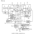
- FIG. 12 shows an example of the general configuration in accordance with the fourth embodiment.
- the same reference numerals are applied to the same elements as those shown in FIG. 9 explained in the third embodiment, and the detailed explanation thereof is omitted.
- the AC/DC converter 3a is connected to the generator 2, and there are provided a current detector 303 for detecting a converter direct current, which is the current on the direct current side of the AC/DC converter 3a, a converter power calculating section 304, and the converter control section 201 for controlling the AC/DC converter 3a.
- the AC/DC converter 3a and the converter control section 201 are equivalent to those explained in the second embodiment.
- the converter power calculating section 304 calculates converter power Pc from the product of the converter direct current times the electricity storage device voltage Vb. However, in the case where the power is converted from the direct current side to the alternating current side of the AC/DC converter 3a, the sign of the converter power Pc is made positive.
- a subtracter 106b receives the inverter power Pi sent from the inverter power calculating section 302, the chargeable power Pb* sent from the electricity storage amount control section 105a, and the converter power Pc sent from the converter power calculating section 304, and subtracts the chargeable power Pb* and the converter power Pc from the inverter power Pi to output the power difference ⁇ P.
- the brake chopper control section 107a receives the power difference ⁇ P from the subtracter 106b, and calculates the conduction ratio VBr so that the power difference ⁇ P and the power consumption of the brake chopper 4 coincide with each other to control the brake chopper 4.
- This example differs from third embodiment in that some of the inverter power Pi is consumed by the engine 1 via the AC/DC converter 3a and the generator 2. Therefore, the power charged in the electricity storage device 5 is the amount of power obtained by excluding the converter power Pc and the power consumption in the brake chopper 4 from the inverter power Pi. Therefore, in the case where the electricity storage amount SOC exceeds the electricity storage upper limit, the power consumption in the brake chopper 4 is controlled so as to be the amount of power obtained by subtracting the chargeable power Pb* and the converter power Pc from the inverter power Pi, by which the power charged in the electricity storage device 5 coincides with the chargeable power Pb*, and becomes zero. Thereby, as in the third embodiment, the electricity storage amount SOC is kept constant. Also, as in the second embodiment, the capacity of the brake chopper 4 can be reduced.
- an efficient operation can be realized by storing the regenerative energy in the electricity storage device and using it effectively. Further, even in the case where the electricity storage amount of the electricity storage device exceeds the upper limit, the regenerative energy can be consumed by the brake chopper, so that the mechanical brake need not be used, and the maintenance of mechanical brake can be eliminated.
Landscapes
- Engineering & Computer Science (AREA)
- Transportation (AREA)
- Mechanical Engineering (AREA)
- Combustion & Propulsion (AREA)
- Chemical & Material Sciences (AREA)
- Power Engineering (AREA)
- Automation & Control Theory (AREA)
- Sustainable Energy (AREA)
- Sustainable Development (AREA)
- Life Sciences & Earth Sciences (AREA)
- Physics & Mathematics (AREA)
- Electromagnetism (AREA)
- Electric Propulsion And Braking For Vehicles (AREA)
Applications Claiming Priority (1)
| Application Number | Priority Date | Filing Date | Title |
|---|---|---|---|
| JP2006183620A JP2008017563A (ja) | 2006-07-03 | 2006-07-03 | 車両制御装置、車両制御方法及び車両 |
Publications (1)
| Publication Number | Publication Date |
|---|---|
| EP1876082A2 true EP1876082A2 (de) | 2008-01-09 |
Family
ID=38626185
Family Applications (1)
| Application Number | Title | Priority Date | Filing Date |
|---|---|---|---|
| EP07252667A Withdrawn EP1876082A2 (de) | 2006-07-03 | 2007-07-02 | Fahrzeugsteuerungseinheit, Fahrzeugsteuerungsverfahren und Fahrzeug |
Country Status (3)
| Country | Link |
|---|---|
| EP (1) | EP1876082A2 (de) |
| JP (1) | JP2008017563A (de) |
| CN (1) | CN101100170A (de) |
Cited By (11)
| Publication number | Priority date | Publication date | Assignee | Title |
|---|---|---|---|---|
| WO2010019784A3 (en) * | 2008-08-14 | 2010-05-20 | General Electric Company | Vehicle, system and method |
| EP2193969A1 (de) | 2008-12-05 | 2010-06-09 | Hitachi Ltd. | Fahrzeugsteuerungssystem |
| WO2012045522A1 (de) * | 2010-10-08 | 2012-04-12 | Robert Bosch Gmbh | Hybridantriebseinrichtung |
| CN102307746B (zh) * | 2009-02-09 | 2012-08-29 | 丰田自动车株式会社 | 电源系统以及具备该电源系统的电动车辆 |
| WO2013026459A1 (de) * | 2011-08-25 | 2013-02-28 | Audi Ag | Verfahren zum bremsen eines kraftfahrzeugs |
| FR3002905A1 (fr) * | 2013-03-05 | 2014-09-12 | Peugeot Citroen Automobiles Sa | Procede de pilotage d'une machine electrique d'un vehicule automobile hybride |
| WO2014154735A3 (de) * | 2013-03-26 | 2014-12-31 | Continental Automotive Gmbh | Verfahren zum betreiben einer rekuperationsbremseinrichtung eines kraftfahrzeugs und rekuperationsbremseinrichtung für ein kraftfahrzeug |
| DE102017213051A1 (de) * | 2017-07-28 | 2019-01-31 | Continental Teves Ag & Co. Ohg | Verfahren zur Lastflussregelung, Lastflussregler und Lastflussregelsystem |
| EP3353374A4 (de) * | 2015-09-22 | 2019-05-22 | Services Petroliers Schlumberger | Bohrlochgeneratorsystem |
| CN110406527A (zh) * | 2018-04-27 | 2019-11-05 | 通用电气全球采购有限责任公司 | 用于具有动态制动的车辆的控制系统和方法 |
| EP4406772A1 (de) * | 2023-01-26 | 2024-07-31 | ALSTOM Holdings | Schienenfahrzeug mit stromspeicherung |
Families Citing this family (12)
| Publication number | Priority date | Publication date | Assignee | Title |
|---|---|---|---|---|
| JP5077295B2 (ja) * | 2009-06-16 | 2012-11-21 | トヨタ自動車株式会社 | 車両搭載用燃料電池システム |
| JP5010645B2 (ja) * | 2009-07-07 | 2012-08-29 | 株式会社東芝 | 電気車制御装置 |
| JP5415619B2 (ja) * | 2010-07-15 | 2014-02-12 | 日立建機株式会社 | 電動式作業車両 |
| FR2975243B1 (fr) * | 2011-05-13 | 2013-04-26 | Michelin Soc Tech | Dispositif et procede de gestion du freinage electrique d'un vehicule |
| JP5425849B2 (ja) * | 2011-09-14 | 2014-02-26 | 株式会社日立製作所 | 鉄道車両の駆動制御装置 |
| FR3013295B1 (fr) * | 2013-11-18 | 2015-12-18 | Peugeot Citroen Automobiles Sa | Procede de commande d'un alternateur associe a un moteur thermique de vehicule automobile |
| CN103676850B (zh) * | 2013-11-27 | 2017-04-12 | 中车唐山机车车辆有限公司 | Tcms通信系统以及通信故障检测方法 |
| CN105751902B (zh) * | 2016-03-31 | 2017-08-29 | 湖北师范学院 | 一种电机全电子再生制动能量回收系统 |
| JP7188871B2 (ja) * | 2017-06-28 | 2022-12-13 | トヨタ自動車株式会社 | 貨物自動車 |
| CN108128171A (zh) * | 2017-12-21 | 2018-06-08 | 成都客车股份有限公司 | 电动汽车的制动能量回馈系统与电缓速方法 |
| DE102020215604A1 (de) * | 2020-12-10 | 2022-06-15 | Robert Bosch Gesellschaft mit beschränkter Haftung | Ansteuerschaltung für eine elektrische Maschine, elektrisches Antriebssystem und Verfahren zum Abbremsen einer elektrischen Maschine |
| CN115214371A (zh) * | 2021-12-17 | 2022-10-21 | 广州汽车集团股份有限公司 | 一种车辆附件控制方法、控制器及存储介质 |
Citations (1)
| Publication number | Priority date | Publication date | Assignee | Title |
|---|---|---|---|---|
| JP2003134604A (ja) | 2001-10-19 | 2003-05-09 | Hitachi Ltd | 鉄道車両 |
-
2006
- 2006-07-03 JP JP2006183620A patent/JP2008017563A/ja active Pending
-
2007
- 2007-06-29 CN CNA2007101263038A patent/CN101100170A/zh active Pending
- 2007-07-02 EP EP07252667A patent/EP1876082A2/de not_active Withdrawn
Patent Citations (1)
| Publication number | Priority date | Publication date | Assignee | Title |
|---|---|---|---|---|
| JP2003134604A (ja) | 2001-10-19 | 2003-05-09 | Hitachi Ltd | 鉄道車両 |
Cited By (16)
| Publication number | Priority date | Publication date | Assignee | Title |
|---|---|---|---|---|
| WO2010019784A3 (en) * | 2008-08-14 | 2010-05-20 | General Electric Company | Vehicle, system and method |
| EP2193969A1 (de) | 2008-12-05 | 2010-06-09 | Hitachi Ltd. | Fahrzeugsteuerungssystem |
| EP2394837A4 (de) * | 2009-02-09 | 2014-10-22 | Toyota Motor Co Ltd | Energieversorgungssystem und elektrofahrzeug damit |
| CN102307746B (zh) * | 2009-02-09 | 2012-08-29 | 丰田自动车株式会社 | 电源系统以及具备该电源系统的电动车辆 |
| WO2012045522A1 (de) * | 2010-10-08 | 2012-04-12 | Robert Bosch Gmbh | Hybridantriebseinrichtung |
| US9401617B2 (en) | 2010-10-08 | 2016-07-26 | Robert Bosch Gmbh | Hybrid drive device |
| US9242565B2 (en) | 2011-08-25 | 2016-01-26 | Audi Ag | Method for braking of a motor vehicle |
| WO2013026459A1 (de) * | 2011-08-25 | 2013-02-28 | Audi Ag | Verfahren zum bremsen eines kraftfahrzeugs |
| FR3002905A1 (fr) * | 2013-03-05 | 2014-09-12 | Peugeot Citroen Automobiles Sa | Procede de pilotage d'une machine electrique d'un vehicule automobile hybride |
| WO2014154735A3 (de) * | 2013-03-26 | 2014-12-31 | Continental Automotive Gmbh | Verfahren zum betreiben einer rekuperationsbremseinrichtung eines kraftfahrzeugs und rekuperationsbremseinrichtung für ein kraftfahrzeug |
| EP3353374A4 (de) * | 2015-09-22 | 2019-05-22 | Services Petroliers Schlumberger | Bohrlochgeneratorsystem |
| DE102017213051A1 (de) * | 2017-07-28 | 2019-01-31 | Continental Teves Ag & Co. Ohg | Verfahren zur Lastflussregelung, Lastflussregler und Lastflussregelsystem |
| CN110406527A (zh) * | 2018-04-27 | 2019-11-05 | 通用电气全球采购有限责任公司 | 用于具有动态制动的车辆的控制系统和方法 |
| CN110406527B (zh) * | 2018-04-27 | 2022-09-02 | Ip传输控股公司 | 用于具有动态制动的车辆的控制系统和方法 |
| EP4406772A1 (de) * | 2023-01-26 | 2024-07-31 | ALSTOM Holdings | Schienenfahrzeug mit stromspeicherung |
| FR3145317A1 (fr) * | 2023-01-26 | 2024-08-02 | Alstom Holdings | Véhicule ferroviaire à stockage d’énergie électrique |
Also Published As
| Publication number | Publication date |
|---|---|
| JP2008017563A (ja) | 2008-01-24 |
| CN101100170A (zh) | 2008-01-09 |
Similar Documents
| Publication | Publication Date | Title |
|---|---|---|
| US8820445B2 (en) | Charge/discharge control device and charge/discharge control method for power storage device, and electric-powered vehicle | |
| EP2326586B1 (de) | Verwaltung von energie von mehreren quellen in einem aufzugsenergiesystem | |
| CN101100170A (zh) | 车辆控制装置、车辆控制方法以及车辆 | |
| US7317295B2 (en) | Electric motor driving system, electric four-wheel drive vehicle, and hybrid vehicle | |
| US8886479B2 (en) | Charge state detecting device for battery pack and method for detecting charge state | |
| EP3640103A1 (de) | Kraftregenerationssystem für arbeitsfahrzeuge | |
| US20180208075A1 (en) | Control device for electric vehicle and electric vehicle | |
| US8907612B2 (en) | Inverter for driving an electric motor comprising an integrated regulator | |
| US10239530B2 (en) | Vehicle control apparatus for a regenerative braking system based on the battery input power | |
| EP2193969A1 (de) | Fahrzeugsteuerungssystem | |
| JP2008295300A (ja) | 蓄電器を備えた車両の電力制限装置 | |
| US12371022B2 (en) | Optimizing regenerative braking | |
| JP2019122201A (ja) | 電動車両 | |
| US10293708B2 (en) | Recuperative brake on a vehicle | |
| WO2022117857A1 (en) | Method and device for controlling an electric drive system for an electric vehicle | |
| JP5069484B2 (ja) | ハイブリッド車両の制御装置 | |
| JP2016119746A (ja) | モータ制御システム | |
| JP5772209B2 (ja) | 蓄電装置の充放電制御装置およびそれを搭載した電動車両 | |
| KR102726817B1 (ko) | 차량의 전기장치 출력 제어 방법 | |
| JPH09308117A (ja) | バッテリ残存容量測定装置 | |
| JP2009055784A (ja) | 車両制御装置、車両制御方法及び車両 | |
| CN108544928B (zh) | 制动载荷控制系统、电动汽车及制动载荷分配方法 | |
| JP2023047001A (ja) | 電気自動車 | |
| JP2022176630A (ja) | 電気自動車 | |
| JP2017073934A (ja) | 電源制御装置 |
Legal Events
| Date | Code | Title | Description |
|---|---|---|---|
| PUAI | Public reference made under article 153(3) epc to a published international application that has entered the european phase |
Free format text: ORIGINAL CODE: 0009012 |
|
| 17P | Request for examination filed |
Effective date: 20070723 |
|
| AK | Designated contracting states |
Kind code of ref document: A2 Designated state(s): AT BE BG CH CY CZ DE DK EE ES FI FR GB GR HU IE IS IT LI LT LU LV MC MT NL PL PT RO SE SI SK TR |
|
| AX | Request for extension of the european patent |
Extension state: AL BA HR MK YU |
|
| STAA | Information on the status of an ep patent application or granted ep patent |
Free format text: STATUS: THE APPLICATION HAS BEEN WITHDRAWN |
|
| 18W | Application withdrawn |
Effective date: 20091116 |