EP1876115B1 - Conteneur de forme parallélépipèdique, en particulier conteneur ISO, pour matières granuleuses - Google Patents
Conteneur de forme parallélépipèdique, en particulier conteneur ISO, pour matières granuleuses Download PDFInfo
- Publication number
- EP1876115B1 EP1876115B1 EP07012558A EP07012558A EP1876115B1 EP 1876115 B1 EP1876115 B1 EP 1876115B1 EP 07012558 A EP07012558 A EP 07012558A EP 07012558 A EP07012558 A EP 07012558A EP 1876115 B1 EP1876115 B1 EP 1876115B1
- Authority
- EP
- European Patent Office
- Prior art keywords
- bulk material
- wall
- material container
- container according
- side wall
- Prior art date
- Legal status (The legal status is an assumption and is not a legal conclusion. Google has not performed a legal analysis and makes no representation as to the accuracy of the status listed.)
- Active
Links
- 239000013590 bulk material Substances 0.000 title claims description 63
- 238000000034 method Methods 0.000 description 3
- 238000005192 partition Methods 0.000 description 3
- 230000005540 biological transmission Effects 0.000 description 2
- 230000000295 complement effect Effects 0.000 description 2
- 230000000694 effects Effects 0.000 description 2
- 238000007789 sealing Methods 0.000 description 2
- 229910000831 Steel Inorganic materials 0.000 description 1
- 238000005429 filling process Methods 0.000 description 1
- 238000009434 installation Methods 0.000 description 1
- 230000014759 maintenance of location Effects 0.000 description 1
- 239000010959 steel Substances 0.000 description 1
- 239000000725 suspension Substances 0.000 description 1
Images


Classifications
-
- B—PERFORMING OPERATIONS; TRANSPORTING
- B65—CONVEYING; PACKING; STORING; HANDLING THIN OR FILAMENTARY MATERIAL
- B65D—CONTAINERS FOR STORAGE OR TRANSPORT OF ARTICLES OR MATERIALS, e.g. BAGS, BARRELS, BOTTLES, BOXES, CANS, CARTONS, CRATES, DRUMS, JARS, TANKS, HOPPERS, FORWARDING CONTAINERS; ACCESSORIES, CLOSURES, OR FITTINGS THEREFOR; PACKAGING ELEMENTS; PACKAGES
- B65D88/00—Large containers
- B65D88/02—Large containers rigid
- B65D88/12—Large containers rigid specially adapted for transport
- B65D88/122—Large containers rigid specially adapted for transport with access from above
- B65D88/124—Large containers rigid specially adapted for transport with access from above closable top
- B65D88/126—Large containers rigid specially adapted for transport with access from above closable top by rigid element, e.g. lid
-
- B—PERFORMING OPERATIONS; TRANSPORTING
- B65—CONVEYING; PACKING; STORING; HANDLING THIN OR FILAMENTARY MATERIAL
- B65D—CONTAINERS FOR STORAGE OR TRANSPORT OF ARTICLES OR MATERIALS, e.g. BAGS, BARRELS, BOTTLES, BOXES, CANS, CARTONS, CRATES, DRUMS, JARS, TANKS, HOPPERS, FORWARDING CONTAINERS; ACCESSORIES, CLOSURES, OR FITTINGS THEREFOR; PACKAGING ELEMENTS; PACKAGES
- B65D88/00—Large containers
- B65D88/02—Large containers rigid
- B65D88/12—Large containers rigid specially adapted for transport
- B65D88/127—Large containers rigid specially adapted for transport open-sided container, i.e. having substantially the whole side free to provide access, with or without closures
-
- B—PERFORMING OPERATIONS; TRANSPORTING
- B65—CONVEYING; PACKING; STORING; HANDLING THIN OR FILAMENTARY MATERIAL
- B65D—CONTAINERS FOR STORAGE OR TRANSPORT OF ARTICLES OR MATERIALS, e.g. BAGS, BARRELS, BOTTLES, BOXES, CANS, CARTONS, CRATES, DRUMS, JARS, TANKS, HOPPERS, FORWARDING CONTAINERS; ACCESSORIES, CLOSURES, OR FITTINGS THEREFOR; PACKAGING ELEMENTS; PACKAGES
- B65D90/00—Component parts, details or accessories for large containers
- B65D90/008—Doors for containers, e.g. ISO-containers
- B65D90/0086—Doors for containers, e.g. ISO-containers rotating or wound around a horizontal axis
Definitions
- the invention relates to a bulk container in cuboid shape, in particular as an ISO container, with horizontal bottom and top walls, two vertical Lijns109wandache and two vertical Querorganwandept and with an upper-side cover portion extending to the second Leksishwandung and by means of an opening kinematics from the plane of Ceiling wall can be folded up about a horizontal pivot axis, which runs parallel to the Leksswandeptept, and with an outlet opening on the first transverse side wall, which is closable with an outlet flap.
- an exit opening is provided in one of the two transverse side walls, which is closable with an outlet flap.
- the outlet opening is relatively small and arranged in the region of the bottom wall. This requires the installation of baffles for guiding the bulk material to the outlet opening.
- the baffles significantly reduce the transport volume of the bulk container.
- the emptying is done by a door attached to the transverse side wall, which is sized so large that baffles are not required, but a complete unloading can be effected by opening the door and tilting the bulk container.
- an exit opening which is closed with doors, is dangerous for an operator when opening the doors, since even the slight opening of a door wing allows the bulk material to flow out, with the risk that the operator will be seized by the bulk material and thereby injured becomes.
- trucks are known with a box-like structure, which have a hinged about a horizontal pivot axis lid portion at the edge remote from the pivot axis a right angle downwardly angled wall segment connects.
- the wall segment extends over the entire height of the longitudinal side wall (see. DE 12 88 927 B . US 2006/0022489 A1 ) or over the larger part of the side wall, wherein the lower part is hinged (see. US 6,247,747 B1 ).
- the possibility should be opened to load the structure from the side.
- goods to be transported goods are specified.
- For the transport of bulk such vehicles are inadequate load capacity taking advantage of the transport space in question.
- the invention has for its object to form a bulk material container of the type mentioned in such a way that it can be loaded and unloaded easier and safer with bulk material in particular by means of wheel loaders.
- the lid portion at the edge remote from the pivot axis a right-angled down wall segment and the second Lutzsdorfwandung has an upwardly open wall cutout, in which encloses the Wandungssegment in the closed state of the lid portion by filling the Wandungsausitess, wherein the height of the wall portion is at least 1/4 and at most 1/2 of the height of the second Lutzsdorfwandung, and that the outlet flap is suspended at its upper edge about a horizontal axis folded up.
- the basic idea of the invention is to provide a wall cutout on the longitudinal side wall over which the loading process is carried out, so that the longitudinal side wall in the region of the wall cutout and thus the loading edge is lower, with the consequence that it is no longer necessary when loaded with a wheel loader is to build a ramp to start the wheel loader.
- the lower loading edge gives in the area of the wall cutout The driver of the wheel loader better visibility. This allows him to position the blade more accurately, so that misloads are avoided, so the entire bulk material in the blade passes into the bulk container. In the closed state, there is no risk of loss of bulk material, because the wall cutout in the longitudinal side wall is filled by the wall segment mounted at right angles to the cover section, so that the bulk material container is then completely closed.
- the height of the wall cutout or the wall segment is dimensioned so that on the one hand the most complete loadability is ensured with bulk material and on the other hand, the loading is greatly facilitated.
- the special suspension of the outlet flap facilitates the unloading of the bulk container, because after opening a closing device, the outlet flap is pushed open by the pressure of the bulk material by itself.
- the wall section and the wall segment expediently have a rectangular shape, but at least a horizontal lower edge.
- the lower edge of the wall segment and the upper edge of the second longitudinal side wall in the region of the wall cutout should have complementary wedge shape. Due to the wedge shape it is ensured that no bulk material can remain in the closing area and the closing area remains clean.
- the width of the wall cut-out should be at least such that conventional wheel loaders can drive their bucket into the wall cut-out.
- the wall cutout should be at least 2/3 of the longitudinal extent of the second longitudinal side wall.
- the wall cutout can also extend over the entire length of the bulk container.
- the pivot axis of the lid portion should extend in the remote with respect to the Wandungssegment half of the top wall to provide a sufficiently large loading opening can.
- the pivot axis is arranged so that it extends in the region of the plane of the first longitudinal side wall, so that the cover portion extends over the entire width of the top wall and thus it provides a large filling opening in the open state.
- the pivot axis of the lid portion extends below the plane of the top wall, and expediently so that the lid portion at the edge adjacent the pivot axis has a right-angled downward wall segment and the first longitudinal side wall has an upwardly open cutout , in which the Wandungssegment engages in the closed state of the lid portion by filling the cutout, wherein the pivot axis extends in the region of the lower edge of the cutout.
- the extension of the lid portion in the longitudinal direction of the bulk container must not be identical to the extension of the Wandungssegmentes in the same direction. Conveniently, however, these two dimensions should be identical.
- the opening kinematics is advantageously arranged in the region of the second transverse side wall, that is to say at the end of the bulk goods container remote from the outlet opening. It is expediently arranged on the inside of the second transverse side wall, since they are there against external influences is protected and does not change the standard external dimensions of the bulk container.
- the opening kinematics should be encapsulated towards the interior of the bulk goods container, so that the bulk material can not damage the opening kinematics.
- This can be done, for example, in the form that the opening kinematics between the second transverse side wall and a partition wall is arranged, which extends advantageously over the entire inner cross section of the bulk container. In particular, this can be done in such a way that the opening kinematics is arranged in a shaft open only at the top, the opening of which is closed by the lid portion in the closed state.
- the opening kinematics has an externally accessible connection for the attachment of an actuating device, for example a crank or a drive motor.
- the connection is expediently arranged on one of the longitudinal side walls, preferably on the second longitudinal side wall, since in this way the opening and closing of the cover section can be well observed.
- the opening kinematics can be designed, for example, such that a drive shaft, a gearbox which converts the rotational movement of the drive shaft into a translational movement, and a gearbox with the output of the gearbox on the one hand and the cover portion on the other hand connected push rod.
- the push rod can then be divided, namely in a first, connected to the transmission output, axially displaceably guided rod segment and a hinged thereto and the lid portion second rod segment.
- there is a worm gear as it is on the one hand self-locking and thus prevents an automatic lowering of the lid portion and on the other hand with her a high translation is feasible, so that the pivoting of the lid portion can be done without much use of force or with a conventional drill.
- the outlet flap extends at least to the bottom wall, so that the bulk material can emerge freely there. This can be facilitated in the usual way by tilting the bulk material container.
- the outlet flap should be as large as possible, in particular extend over the entire width of the first transverse side wall, so that on the front sides of the L Lucass109wandungen no leakage of the bulk material obstructing projections are present.
- the outlet flap does not have to go over the entire height of the first Quermatiwandung. However, it has proved to be useful if the outlet flap forms the first transverse side wall, so it consists of it, and is suspended from the ceiling wall. This results in the largest possible outlet opening, which allows a fast and complete unloading of the bulk container by opening the outlet flap and easy tilting of the bulk container in the direction of the outlet flap.
- the outlet flap preferably has at its lower edge a closing device, via which the outlet flap can be fixed in the closed position.
- the closing device is advantageously designed such that the outlet flap can be braced against a frame delimiting the outlet opening in order to achieve a good sealing effect.
- the outlet flap ends below the top of the bottom wall and the closing device is arranged inside or below the bottom wall so as to protect against the bulk material.
- the outlet flap may have at least one bracket at the bottom, which in the closed position of the outlet flap has a form-locking connection with the closing device.
- deflectors should be provided above it.
- the locking device is preferably connected to an actuating device which can be actuated on one of the two longitudinal side walls from the outside. In this way, it is avoided in the sense of the second part of the task that an operator who opens the closing device and thus releases the exit flap, is detected by the then flowing bulk material. The operator is then in a safe position next to the associated L josspitwandung and can watch from there the discharge process well.
- the interior of the bulk container has cuboid shape and is provided with smooth walls. In this way, the retention of bulk material nests is avoided.
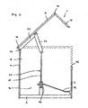
- the in FIG. 1 illustrated bulk container 1 has the usual for ISO container cuboid shape with a horizontal bottom wall 2, an equally horizontal top wall 3, two parallel and vertical Lekstrewandungen 4, 5 and two also vertical and mutually parallel Querboxwandept 7, 8.
- the Leksswandungen 4, 5 are with the bottom wall 2 and the top wall 3 rigidly connected.
- the rear side, second transverse side wall 8 connects not only the bottom wall 2 and the top wall 3, but also the two Lekstrewandungen 4, 5 and thus closes the bulk container 1 from the rear side.
- the first transverse side wall 7 can be pivoted upwards via an upper-side pivot axis 9 on the frame of the bulk material container 1 and thus on the top wall 3 from a vertical position into the oblique position shown, wherein it releases the entire inner cross-section of the bulk material container 1.
- the transverse side wall 7 thus forms an outlet flap for the filled in the bulk material container 1 bulk material.
- the bulk goods container 1 has on the top side a cover section 10 whose width corresponds to the width of the top wall 3 and extends in the longitudinal direction of the bulk container 1 over a large part of the length of the top wall 3.
- the lid portion 10 has a lid plate 11 which is in the closed state in the plane of the top wall 3 and flush with this.
- On the cover plate 11 is followed at the back, ie in the region of the first longitudinal side wall 4, a wall segment 12, which engages in a correspondingly shaped cutout in the first longitudinal side wall 4 and is connected thereto via a pivot axis 13.
- the pivot axis 13 extends on the upper edge of the cutout in the first longitudinal side wall 4.
- About the pivot axis 13 of the entire cover portion 10 of the in the FIGS. 1 and 2 shown pivoted position in a in FIG. 2 Dashed position shown closed position pivoted.
- a Wandungssegment 14 It protrudes at right angles from the cover plate 11 downwards and has a rectangular shape.
- the second longitudinal side wall 5 has a rectangular, upwardly open wall cutout 15 which is congruent with the wall segment 14. In the closed state of the Dekkelabsacrificings 10, the wall segment 14 completely fills the wall cut-out 15 and thus closes the bulk material container 1. In the closed position, the bulk material container 1 can be secured by a securing or tensioning device.
- an opening kinematics 16 is provided for the up and Zuschenken the lid portion 10.
- This opening kinematics is arranged adjacent to the second transverse side wall 8 and to the interior of the bulk container 1 by a partition wall 17 (see. FIG. 1 ; in FIG. 2 omitted).
- the partition wall 17 and the second transverse side wall 8 form an upwardly open shaft.
- the opening kinematics 16 has a crankshaft 18 which extends parallel to the second transverse side wall 8 and extends to the second longitudinal side wall 5.
- the crankshaft 18 leads to a worm gear 19, to which an upwardly extending push rod 20 connects.
- the push rod 20 is divided into a first, exclusively vertically displaceable rod segment 21 which is connected to the output of the worm gear 19, and a second rod segment 22, on the one hand at the upper end of the first rod segment 21 and on the other the underside of a carrier 23 is articulated.
- the carrier 23 is welded to the underside of the cover plate 11.
- the crankshaft 18 is offset from the outside in a corresponding rotational movement. This is then converted in the worm gear 19 in a translational movement, with the result that the first rod segment 21 is displaced vertically.
- this movement is transmitted to the cover plate 11 and then leads to a corresponding pivoting movement between the illustrated open position and a closed position in which the cover plate 11 assumes a horizontal position.
- the bulk material container 1 can be loaded via the second longitudinal side wall 5, for example, by moving the blade of a wheel loader through the wall cutout 15 and then tilting it.
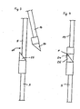
- the lower portions of the wall segment 14 and the upper portions of the second longitudinal side wall 5 can be seen in cross-section.
- the wall segment 14 has at the lower edge of a wedge strip 24 which extends over the entire length of the lower edge.
- a wedge strip 25 is likewise attached, which extends over the entire width of the wall cutout 15.
- the wedges 24, 25 have complementary shape, so that in the closed state of the lid portion 10 they come into planar contact with each other and thereby achieve a good sealing effect.
- the wall portion 14 may have a fixing plate F at the upper end portion of its wedge strip 24, which engages over the wedge strip 25 of the longitudinal side wall in the closed position and prevents the wall portion 14 moves further down.
- the closed position is defined exactly.
- FIG. 5 shows the collision of the first transverse side wall 7 and bottom wall 2.
- a steel strip 26 is fixed, which projects down over the lower edge of the transverse side wall 7 and there has an inwardly directed, U-shaped bracket 27. Over the width of the transverse side wall 7 more such bracket are provided. They each pass through an opening 28 in the end face of the bottom wall 2.
- a closing device 29 is arranged. It has a over the width of the bottom wall extending closing shaft 30, sitting on the locking hooks 31 rotatably, each with a locking hook 31 is associated with a bracket 27.
- a fork 32 is additionally mounted rotationally fixed, in which an actuating lever 33 engages.
- the actuating lever 33 is mounted on an actuating rod 34 which projects outward on one of the longitudinal side walls 4, 5 and There can be put into rotation by attaching a crank or the like.
- a safety device is provided to prevent accidental operation.
- the transverse side wall 7 is braced against the end face of the bottom wall 2, because the hook-shaped ends of the locking hooks 31 each engage in a bracket 27.
- the actuating rod 34 is rotated from the outside by means of a crank in a clockwise direction.
- the closing shaft 30 and the attached hooks 31 are rotated counterclockwise, so that the hook-like ends of the locking hooks 31 out of the eyelets formed by the bracket 27.
- the transverse side wall 7 is then released. By tilting the bulk material container 1 - in this view counterclockwise - the leaking bulk material for unfolding the transverse side wall 7, as shown in question 1.
- bracket 27 Abweisbleche 35 are mounted, which ensure in the open state of the transverse side wall 7 that the bracket 27 are protected, so are not torn off by the expiring bulk material.
Landscapes
- Engineering & Computer Science (AREA)
- Mechanical Engineering (AREA)
- Closures For Containers (AREA)
- Buffer Packaging (AREA)
- Baking, Grill, Roasting (AREA)
- Containers Having Bodies Formed In One Piece (AREA)
- Transition And Organic Metals Composition Catalysts For Addition Polymerization (AREA)
Claims (27)
- Conteneur (1) de forme parallélépipédique pour matières en vrac, se présentant notamment comme un conteneur ISO comprenant des parois horizontales (2, 3) de fond et de dessus ; deux parois verticales (4, 5) de côtés longitudinaux et deux parois verticales (7, 8) de côtés transversaux ; une région supérieure (10) formant couvercle, qui s'étend jusqu'à la seconde paroi (5) de côté longitudinal et peut être relevée par pivotement autour d'un axe horizontal de pivotement (13), au moyen d'un mécanisme d'ouverture (16), pour sortir du plan de la paroi (3) de dessus, lequel axe s'étend parallèlement aux parois (4, 5) de côtés longitudinaux ; ainsi qu'un orifice de sortie pratiqué au niveau de la première paroi (7) de côté transversal, et pouvant être obturé par un volet de sortie, caractérisé par le fait que la région (10) formant couvercle comporte, sur le bord éloigné de l'axe de pivotement (13), un segment de paroi (14) coudé à angle droit vers le bas, et la seconde paroi (5) de côté longitudinal présente une découpe (15) ouverte vers le haut et dans laquelle ledit segment de paroi (14) vient se nicher à l'état fermé de ladite région (10) formant couvercle, avec occultation intégrale de ladite découpe (15), la hauteur de ladite découpe (15) représentant au minimum 1/4 et, au maximum, la moitié de la hauteur de la seconde paroi (5) de côté longitudinal ; et par le fait que le volet de sortie (7) est suspendu, sur son bord supérieur, avec faculté de pivotement vers le haut autour d'un axe horizontal (9).
- Conteneur pour matières en vrac, selon la revendication 1, caractérisé par le fait que la découpe (15) de la paroi, et le segment de paroi (14), possèdent une forme rectangulaire.
- Conteneur pour matières en vrac, selon la revendication 1 ou 2, caractérisé par le fait que le bord inférieur (24) du segment de paroi (14), et le bord supérieur (25) de la découpe (15) de la paroi, possèdent un profil cunéiforme.
- Conteneur pour matières en vrac, selon l'une des revendications 1 à 3, caractérisé par le fait que la largeur de la découpe (15) de la paroi représente au moins les 2/3 de l'étendue longitudinale de la seconde paroi (5) de côté longitudinal.
- Conteneur pour matières en vrac, selon l'une des revendications 1 à 4, caractérisé par le fait que l'axe de pivotement (13) de la région (10) formant couvercle s'étend dans la région du plan de la première paroi (4) de côté longitudinal.
- Conteneur pour matières en vrac, selon la revendication 5, caractérisé par le fait que l'axe de pivotement (13) de la région (10) formant couvercle s'étend au-dessous du plan de la paroi (3) de dessus.
- Conteneur pour matières en vrac, selon la revendication 6, caractérisé par le fait que la région (10) formant couvercle comporte, sur le bord voisin de l'axe de pivotement (13), un segment de paroi (12) coudé à angle droit vers le bas, et la première paroi (4) de côté longitudinal présente une découpe ouverte vers le haut et dans laquelle ledit segment de paroi (12) vient se nicher à l'état fermé de ladite région (10) formant couvercle, avec occultation intégrale de ladite découpe, ledit axe de pivotement (13) s'étendant dans la zone du bord inférieur de ladite découpe.
- Conteneur pour matières en vrac, selon l'une des revendications 1 à 7, caractérisé par le fait que le mécanisme d'ouverture (16) est disposé dans la région de la seconde paroi (8) de côté transversal.
- Conteneur pour matières en vrac, selon la revendication 8, caractérisé par le fait que le mécanisme d'ouverture (16) est disposé à la face inférieure de la seconde paroi (8) de côté transversal.
- Conteneur pour matières en vrac, selon la revendication 9, caractérisé par le fait que le mécanisme d'ouverture (16) est encapsulé en direction de l'espace interne dudit conteneur (1) pour matières en vrac.
- Conteneur pour matières en vrac, selon la revendication 10, caractérisé par le fait que le mécanisme d'ouverture (16) est interposé entre une cloison séparatrice (17) et la seconde paroi (8) de côté transversal.
- Conteneur pour matières en vrac, selon la revendication 11, caractérisé par le fait que la cloison séparatrice (17) couvre intégralement la section transversale intérieure dudit conteneur (1) pour matières en vrac.
- Conteneur pour matières en vrac, selon l'une des revendications 9 à 12, caractérisé par le fait que le mécanisme d'ouverture (16) est logé dans un coffrage ouvert uniquement à la face supérieure, dont l'orifice est obturé par la région (10) formant couvercle à l'état fermé.
- Conteneur pour matières en vrac, selon l'une des revendications 1 à 13, caractérisé par le fait que le mécanisme d'ouverture (16) présente un raccord accessible de l'extérieur et destiné à l'engagement d'un système d'actionnement.
- Conteneur pour matières en vrac, selon la revendication 14, caractérisé par le fait que le raccord est disposé sur l'une des parois (4, 5) de côtés longitudinaux.
- Conteneur pour matières en vrac, selon la revendication 15, caractérisé par le fait que le raccord est situé dans la seconde paroi (5) de côté longitudinal.
- Conteneur pour matières en vrac, selon l'une des revendications 1 à 16, caractérisé par le fait que le mécanisme d'ouverture (16) comprend un arbre menant (18) ; une transmission (19) convertissant le mouvement rotatoire dudit arbre menant (18) en un mouvement translatoire ; et une tige de poussée (20) reliée, d'une part, à la sortie de ladite transmission (19) et, d'autre part, à la région (10) formant couvercle.
- Conteneur pour matières en vrac, selon la revendication 17, caractérisé par le fait que la tige de poussée (20) comprend un premier segment (21) guidé à coulissements axiaux et relié à la sortie de la transmission ; et un second segment (22) relié, de manière articulée, au segment précité et à la région (10) formant couvercle.
- Conteneur pour matières en vrac, selon la revendication 17 ou 18, caractérisé par le fait que la transmission est réalisée sous la forme d'un engrenage (19) à vis sans fin.
- Conteneur pour matières en vrac, selon l'une des revendications 1 à 19, caractérisé par le fait que le volet de sortie (7) matérialise la première paroi de côté transversal, et est suspendu à la paroi (3) de dessus.
- Conteneur pour matières en vrac, selon l'une des revendications 1 à 20, caractérisé par le fait que le volet de sortie (7) présente un système de fermeture (29) dans la région de son bord inférieur.
- Conteneur pour matières en vrac, selon la revendication 21, caractérisé par le fait que le système de fermeture (29) est réalisé de telle sorte que le volet de sortie (7) puisse être bloqué contre un cadre délimitant périphériquement l'orifice de sortie.
- Conteneur pour matières en vrac, selon la revendication 21 ou 22, caractérisé par le fait que le volet de sortie (7) s'achève au-dessous de la face supérieure de la paroi de fond (2), et le système de fermeture (29) est disposé à l'intérieur ou au-dessous de ladite paroi de fond (2).
- Conteneur pour matières en vrac, selon la revendication 23, caractérisé par le fait que le volet de sortie (7) comporte, intérieurement, au moins un étrier (27) présentant, en position fermée dudit volet de sortie (7), une liaison par concordance de formes avec le système de fermeture (29).
- Conteneur pour matières en vrac, selon la revendication 24, caractérisé par le fait qu'une tôle déflectrice (35) est respectivement présente au-dessus de l'étrier ou des étriers (27).
- Conteneur pour matières en vrac, selon l'une des revendications 21 à 25, caractérisé par le fait que le système de fermeture (29) est relié à un système d'actionnement (34) pouvant être manoeuvré, depuis l'extérieur, sur l'une des deux parois (4, 5) de côtés longitudinaux.
- Conteneur pour matières en vrac, selon l'une des revendications 1 à 26, caractérisé par le fait que l'espace interne dudit conteneur (1) pour matières en vrac offre une forme parallélépipédique à parois lisses.
Applications Claiming Priority (1)
| Application Number | Priority Date | Filing Date | Title |
|---|---|---|---|
| DE202006010375U DE202006010375U1 (de) | 2006-07-03 | 2006-07-03 | Schüttgutcontainer in Quaderform, insbesondere als ISO-Container |
Publications (3)
| Publication Number | Publication Date |
|---|---|
| EP1876115A2 EP1876115A2 (fr) | 2008-01-09 |
| EP1876115A3 EP1876115A3 (fr) | 2008-03-19 |
| EP1876115B1 true EP1876115B1 (fr) | 2010-04-07 |
Family
ID=38513808
Family Applications (1)
| Application Number | Title | Priority Date | Filing Date |
|---|---|---|---|
| EP07012558A Active EP1876115B1 (fr) | 2006-07-03 | 2007-06-27 | Conteneur de forme parallélépipèdique, en particulier conteneur ISO, pour matières granuleuses |
Country Status (3)
| Country | Link |
|---|---|
| EP (1) | EP1876115B1 (fr) |
| AT (1) | ATE463447T1 (fr) |
| DE (2) | DE202006010375U1 (fr) |
Cited By (1)
| Publication number | Priority date | Publication date | Assignee | Title |
|---|---|---|---|---|
| EP3753866A1 (fr) | 2019-06-20 | 2020-12-23 | PeLift AB | Mécanisme de commande pour l'ouverture et la fermeture d'un couvercle de récipient |
Families Citing this family (4)
| Publication number | Priority date | Publication date | Assignee | Title |
|---|---|---|---|---|
| GB2506865A (en) * | 2012-10-09 | 2014-04-16 | Sita Reenergy Rotterdam B V | Intermodal container with hinged roof and/or end wall |
| CN108952293B (zh) * | 2018-10-18 | 2024-04-05 | 吉林建筑大学 | 一种家庭应急避险方仓 |
| CN113233029B (zh) * | 2021-06-10 | 2022-08-05 | 眉山中车物流装备有限公司 | 一种新型轻量化自卸集装箱 |
| US11878859B2 (en) * | 2021-08-02 | 2024-01-23 | Cakeboxx Technologies, Llc | Side wing opening container |
Family Cites Families (17)
| Publication number | Priority date | Publication date | Assignee | Title |
|---|---|---|---|---|
| DE1288927B (de) * | 1962-10-27 | 1969-02-06 | Continental Gummi Werke Ag | Nutzfahrzeug, insbesondere Strassenfahrzeug |
| GB1206689A (en) * | 1968-10-28 | 1970-09-30 | Nat Carbonising Company Ltd | Improvements in containers |
| DE2809375A1 (de) * | 1978-03-04 | 1979-09-13 | Guenter Peters | Lastkraftwagen mit ladepritsche und aufbau |
| DE2952225A1 (de) * | 1979-12-22 | 1981-07-02 | Heinz 4474 Lathen Bergmann | Tuerverschluss fuer tueren und deckel von behaeltern |
| KR940007559B1 (ko) * | 1984-11-05 | 1994-08-20 | 가부시기가이샤 산요오 미까와 보데 | 하물(荷物) 적재대 |
| JPS6344482A (ja) * | 1986-07-31 | 1988-02-25 | 日綜産業株式会社 | 折り畳み自在なコンテナ |
| DE3705202C1 (en) * | 1987-02-19 | 1988-03-03 | Heinz Bergmann | Container |
| EP0787643B1 (fr) * | 1995-08-22 | 2002-07-17 | Toray Industries, Inc. | Panneau et compartiment de fret pour camion |
| AUPQ726700A0 (en) * | 2000-05-03 | 2000-05-25 | Christakos, George | Containment system |
| FI20001260L (fi) | 2000-05-03 | 2001-12-03 | Oy Langh Ship Ab | Kontti |
| US6732883B2 (en) * | 2000-10-27 | 2004-05-11 | Wastequip Manufacturing Company | Waste container with displaceable panel closure |
| FI5314U1 (fi) * | 2001-11-26 | 2002-04-09 | Oy Langh Ship Ab | Kontti |
| DE20218054U1 (de) | 2002-11-21 | 2003-03-06 | M. Sirch GmbH & Co. KG Apparate und Behälterbau, 87600 Kaufbeuren | Container |
| US6938960B1 (en) * | 2003-06-30 | 2005-09-06 | Caleb Eby | Top-loading container and cover assembly for collecting, storing, handling, and transporting bulk materials |
| DE202004002043U1 (de) * | 2004-02-10 | 2004-06-17 | Richter, Michael | Federunterstützte Hubmechanik für Deckelcontainer |
| US7125068B2 (en) * | 2004-07-28 | 2006-10-24 | Waldorf Merle K | Transfer trailer |
| DE102004053546A1 (de) | 2004-11-05 | 2006-05-11 | Rainer Dirnhofer | Seecontainer zum Transport von Schüttgütern |
-
2006
- 2006-07-03 DE DE202006010375U patent/DE202006010375U1/de not_active Expired - Lifetime
-
2007
- 2007-06-27 DE DE502007003379T patent/DE502007003379D1/de active Active
- 2007-06-27 EP EP07012558A patent/EP1876115B1/fr active Active
- 2007-06-27 AT AT07012558T patent/ATE463447T1/de active
Cited By (1)
| Publication number | Priority date | Publication date | Assignee | Title |
|---|---|---|---|---|
| EP3753866A1 (fr) | 2019-06-20 | 2020-12-23 | PeLift AB | Mécanisme de commande pour l'ouverture et la fermeture d'un couvercle de récipient |
Also Published As
| Publication number | Publication date |
|---|---|
| EP1876115A3 (fr) | 2008-03-19 |
| EP1876115A2 (fr) | 2008-01-09 |
| DE502007003379D1 (de) | 2010-05-20 |
| ATE463447T1 (de) | 2010-04-15 |
| DE202006010375U1 (de) | 2007-09-06 |
Similar Documents
| Publication | Publication Date | Title |
|---|---|---|
| EP2871141B1 (fr) | Conteneur destiné au transport de produits en vrac | |
| EP1876115B1 (fr) | Conteneur de forme parallélépipèdique, en particulier conteneur ISO, pour matières granuleuses | |
| DE3342281A1 (de) | Container mit einem laderaum fuer stueck- und schuettgut | |
| EP0116947B1 (fr) | Conteneur avec dispositif de décharge à sa partie inférieure, particulièrement pour vieux papiers | |
| EP2741975B1 (fr) | Conteneur de transport | |
| DE102010030812A1 (de) | Verdeckvorrichtung für einen Lastentransportbehälter eines Lastentransportfahrzeugs und ein damit ausgerüstetes Lastentransportfahrzeug | |
| DE2830192A1 (de) | Fahrzeugtuer, insbesondere fuer gewerbliche kraftfahrzeuge | |
| CH645580A5 (de) | Lastkraftwagen mit einer ladepritsche und einem aufbau. | |
| DE112010001118T5 (de) | Fester Open-Top-Container | |
| EP1955932A2 (fr) | Mécanisme de fermeture pour une structure de véhicule | |
| EP0379031A2 (fr) | Coffre de toit pour véhicule | |
| DE2651561A1 (de) | Behaelter | |
| AT17104U1 (de) | ISO-Normcontainer | |
| EP2845822A1 (fr) | Conteneur et système comprenant un tel conteneur | |
| EP2428434B1 (fr) | Mécanisme de fermeture pour une structure de véhicule | |
| DE19821298B4 (de) | Toranordnung für von oben beschickbare Lagerbunker | |
| DE4006532A1 (de) | Ladepritsche fuer fahrzeug mit wenigstens einer oeffenbaren seitenwand | |
| EP0319665B1 (fr) | Conteneur | |
| EP0034356A1 (fr) | Dispositif de fermeture avec une barre rotative pour parois rabattables de véhicules de transport | |
| EP2151372A1 (fr) | Plateforme pour véhicules utilitaires comprenant une poutre de soutien des portes arrières | |
| WO2009049835A1 (fr) | Poubelle dotée d'un mécanisme de compression | |
| AT402723B (de) | Seitenwand für den aufbau eines fahrzeuges | |
| DE3929873A1 (de) | Ladebruecke, insbesondere fuer kippfahrzeuge | |
| AT404121B (de) | Müllsammelfahrzeug | |
| DE2261934A1 (de) | Bordwand |
Legal Events
| Date | Code | Title | Description |
|---|---|---|---|
| PUAI | Public reference made under article 153(3) epc to a published international application that has entered the european phase |
Free format text: ORIGINAL CODE: 0009012 |
|
| AK | Designated contracting states |
Kind code of ref document: A2 Designated state(s): AT BE BG CH CY CZ DE DK EE ES FI FR GB GR HU IE IS IT LI LT LU LV MC MT NL PL PT RO SE SI SK TR |
|
| AX | Request for extension of the european patent |
Extension state: AL BA HR MK YU |
|
| PUAL | Search report despatched |
Free format text: ORIGINAL CODE: 0009013 |
|
| AK | Designated contracting states |
Kind code of ref document: A3 Designated state(s): AT BE BG CH CY CZ DE DK EE ES FI FR GB GR HU IE IS IT LI LT LU LV MC MT NL PL PT RO SE SI SK TR |
|
| AX | Request for extension of the european patent |
Extension state: AL BA HR MK YU |
|
| 17P | Request for examination filed |
Effective date: 20080728 |
|
| AKX | Designation fees paid |
Designated state(s): AT BE BG CH CY CZ DE DK EE ES FI FR GB GR HU IE IS IT LI LT LU LV MC MT NL PL PT RO SE SI SK TR |
|
| AXX | Extension fees paid |
Extension state: RS Payment date: 20080728 Extension state: MK Payment date: 20080728 Extension state: BA Payment date: 20080728 Extension state: AL Payment date: 20080728 Extension state: HR Payment date: 20080728 |
|
| GRAP | Despatch of communication of intention to grant a patent |
Free format text: ORIGINAL CODE: EPIDOSNIGR1 |
|
| RTI1 | Title (correction) |
Free format text: CUBOID BULK MATERIAL CONTAINER, IN PARTICULAR AS AN ISO CONTAINER |
|
| GRAS | Grant fee paid |
Free format text: ORIGINAL CODE: EPIDOSNIGR3 |
|
| GRAA | (expected) grant |
Free format text: ORIGINAL CODE: 0009210 |
|
| AK | Designated contracting states |
Kind code of ref document: B1 Designated state(s): AT BE BG CH CY CZ DE DK EE ES FI FR GB GR HU IE IS IT LI LT LU LV MC MT NL PL PT RO SE SI SK TR |
|
| AX | Request for extension of the european patent |
Extension state: AL BA HR MK RS |
|
| REG | Reference to a national code |
Ref country code: GB Ref legal event code: FG4D Free format text: NOT ENGLISH |
|
| REG | Reference to a national code |
Ref country code: CH Ref legal event code: EP |
|
| REG | Reference to a national code |
Ref country code: IE Ref legal event code: FG4D Free format text: LANGUAGE OF EP DOCUMENT: GERMAN |
|
| REF | Corresponds to: |
Ref document number: 502007003379 Country of ref document: DE Date of ref document: 20100520 Kind code of ref document: P |
|
| REG | Reference to a national code |
Ref country code: NL Ref legal event code: VDEP Effective date: 20100407 |
|
| PG25 | Lapsed in a contracting state [announced via postgrant information from national office to epo] |
Ref country code: SI Free format text: LAPSE BECAUSE OF FAILURE TO SUBMIT A TRANSLATION OF THE DESCRIPTION OR TO PAY THE FEE WITHIN THE PRESCRIBED TIME-LIMIT Effective date: 20100407 |
|
| LTIE | Lt: invalidation of european patent or patent extension |
Effective date: 20100407 |
|
| REG | Reference to a national code |
Ref country code: IE Ref legal event code: FD4D |
|
| PG25 | Lapsed in a contracting state [announced via postgrant information from national office to epo] |
Ref country code: LT Free format text: LAPSE BECAUSE OF FAILURE TO SUBMIT A TRANSLATION OF THE DESCRIPTION OR TO PAY THE FEE WITHIN THE PRESCRIBED TIME-LIMIT Effective date: 20100407 Ref country code: ES Free format text: LAPSE BECAUSE OF FAILURE TO SUBMIT A TRANSLATION OF THE DESCRIPTION OR TO PAY THE FEE WITHIN THE PRESCRIBED TIME-LIMIT Effective date: 20100718 Ref country code: NL Free format text: LAPSE BECAUSE OF FAILURE TO SUBMIT A TRANSLATION OF THE DESCRIPTION OR TO PAY THE FEE WITHIN THE PRESCRIBED TIME-LIMIT Effective date: 20100407 Ref country code: SE Free format text: LAPSE BECAUSE OF FAILURE TO SUBMIT A TRANSLATION OF THE DESCRIPTION OR TO PAY THE FEE WITHIN THE PRESCRIBED TIME-LIMIT Effective date: 20100407 |
|
| PG25 | Lapsed in a contracting state [announced via postgrant information from national office to epo] |
Ref country code: FI Free format text: LAPSE BECAUSE OF FAILURE TO SUBMIT A TRANSLATION OF THE DESCRIPTION OR TO PAY THE FEE WITHIN THE PRESCRIBED TIME-LIMIT Effective date: 20100407 Ref country code: IS Free format text: LAPSE BECAUSE OF FAILURE TO SUBMIT A TRANSLATION OF THE DESCRIPTION OR TO PAY THE FEE WITHIN THE PRESCRIBED TIME-LIMIT Effective date: 20100807 Ref country code: LV Free format text: LAPSE BECAUSE OF FAILURE TO SUBMIT A TRANSLATION OF THE DESCRIPTION OR TO PAY THE FEE WITHIN THE PRESCRIBED TIME-LIMIT Effective date: 20100407 |
|
| PGFP | Annual fee paid to national office [announced via postgrant information from national office to epo] |
Ref country code: DE Payment date: 20100529 Year of fee payment: 4 |
|
| BERE | Be: lapsed |
Owner name: NEUSS-DUSSELDORFER HAFEN G.M.B.H. & CO. KG Effective date: 20100630 |
|
| PG25 | Lapsed in a contracting state [announced via postgrant information from national office to epo] |
Ref country code: PL Free format text: LAPSE BECAUSE OF FAILURE TO SUBMIT A TRANSLATION OF THE DESCRIPTION OR TO PAY THE FEE WITHIN THE PRESCRIBED TIME-LIMIT Effective date: 20100407 Ref country code: CY Free format text: LAPSE BECAUSE OF FAILURE TO SUBMIT A TRANSLATION OF THE DESCRIPTION OR TO PAY THE FEE WITHIN THE PRESCRIBED TIME-LIMIT Effective date: 20100519 |
|
| PG25 | Lapsed in a contracting state [announced via postgrant information from national office to epo] |
Ref country code: EE Free format text: LAPSE BECAUSE OF FAILURE TO SUBMIT A TRANSLATION OF THE DESCRIPTION OR TO PAY THE FEE WITHIN THE PRESCRIBED TIME-LIMIT Effective date: 20100407 Ref country code: IE Free format text: LAPSE BECAUSE OF FAILURE TO SUBMIT A TRANSLATION OF THE DESCRIPTION OR TO PAY THE FEE WITHIN THE PRESCRIBED TIME-LIMIT Effective date: 20100407 Ref country code: MC Free format text: LAPSE BECAUSE OF NON-PAYMENT OF DUE FEES Effective date: 20100630 Ref country code: PT Free format text: LAPSE BECAUSE OF FAILURE TO SUBMIT A TRANSLATION OF THE DESCRIPTION OR TO PAY THE FEE WITHIN THE PRESCRIBED TIME-LIMIT Effective date: 20100809 Ref country code: DK Free format text: LAPSE BECAUSE OF FAILURE TO SUBMIT A TRANSLATION OF THE DESCRIPTION OR TO PAY THE FEE WITHIN THE PRESCRIBED TIME-LIMIT Effective date: 20100407 Ref country code: GR Free format text: LAPSE BECAUSE OF FAILURE TO SUBMIT A TRANSLATION OF THE DESCRIPTION OR TO PAY THE FEE WITHIN THE PRESCRIBED TIME-LIMIT Effective date: 20100708 |
|
| PLBE | No opposition filed within time limit |
Free format text: ORIGINAL CODE: 0009261 |
|
| STAA | Information on the status of an ep patent application or granted ep patent |
Free format text: STATUS: NO OPPOSITION FILED WITHIN TIME LIMIT |
|
| PG25 | Lapsed in a contracting state [announced via postgrant information from national office to epo] |
Ref country code: CZ Free format text: LAPSE BECAUSE OF FAILURE TO SUBMIT A TRANSLATION OF THE DESCRIPTION OR TO PAY THE FEE WITHIN THE PRESCRIBED TIME-LIMIT Effective date: 20100407 Ref country code: RO Free format text: LAPSE BECAUSE OF FAILURE TO SUBMIT A TRANSLATION OF THE DESCRIPTION OR TO PAY THE FEE WITHIN THE PRESCRIBED TIME-LIMIT Effective date: 20100407 Ref country code: SK Free format text: LAPSE BECAUSE OF FAILURE TO SUBMIT A TRANSLATION OF THE DESCRIPTION OR TO PAY THE FEE WITHIN THE PRESCRIBED TIME-LIMIT Effective date: 20100407 |
|
| 26N | No opposition filed |
Effective date: 20110110 |
|
| REG | Reference to a national code |
Ref country code: FR Ref legal event code: ST Effective date: 20110228 |
|
| PG25 | Lapsed in a contracting state [announced via postgrant information from national office to epo] |
Ref country code: IT Free format text: LAPSE BECAUSE OF FAILURE TO SUBMIT A TRANSLATION OF THE DESCRIPTION OR TO PAY THE FEE WITHIN THE PRESCRIBED TIME-LIMIT Effective date: 20100407 |
|
| PG25 | Lapsed in a contracting state [announced via postgrant information from national office to epo] |
Ref country code: MT Free format text: LAPSE BECAUSE OF FAILURE TO SUBMIT A TRANSLATION OF THE DESCRIPTION OR TO PAY THE FEE WITHIN THE PRESCRIBED TIME-LIMIT Effective date: 20100407 |
|
| PG25 | Lapsed in a contracting state [announced via postgrant information from national office to epo] |
Ref country code: FR Free format text: LAPSE BECAUSE OF NON-PAYMENT OF DUE FEES Effective date: 20100630 |
|
| PG25 | Lapsed in a contracting state [announced via postgrant information from national office to epo] |
Ref country code: BE Free format text: LAPSE BECAUSE OF NON-PAYMENT OF DUE FEES Effective date: 20100630 |
|
| REG | Reference to a national code |
Ref country code: CH Ref legal event code: PL |
|
| GBPC | Gb: european patent ceased through non-payment of renewal fee |
Effective date: 20110627 |
|
| REG | Reference to a national code |
Ref country code: DE Ref legal event code: R119 Ref document number: 502007003379 Country of ref document: DE Effective date: 20120103 |
|
| PG25 | Lapsed in a contracting state [announced via postgrant information from national office to epo] |
Ref country code: CH Free format text: LAPSE BECAUSE OF NON-PAYMENT OF DUE FEES Effective date: 20110630 Ref country code: LI Free format text: LAPSE BECAUSE OF NON-PAYMENT OF DUE FEES Effective date: 20110630 Ref country code: DE Free format text: LAPSE BECAUSE OF NON-PAYMENT OF DUE FEES Effective date: 20120103 |
|
| PG25 | Lapsed in a contracting state [announced via postgrant information from national office to epo] |
Ref country code: GB Free format text: LAPSE BECAUSE OF NON-PAYMENT OF DUE FEES Effective date: 20110627 |
|
| PG25 | Lapsed in a contracting state [announced via postgrant information from national office to epo] |
Ref country code: BG Free format text: LAPSE BECAUSE OF FAILURE TO SUBMIT A TRANSLATION OF THE DESCRIPTION OR TO PAY THE FEE WITHIN THE PRESCRIBED TIME-LIMIT Effective date: 20100407 Ref country code: HU Free format text: LAPSE BECAUSE OF FAILURE TO SUBMIT A TRANSLATION OF THE DESCRIPTION OR TO PAY THE FEE WITHIN THE PRESCRIBED TIME-LIMIT Effective date: 20101008 Ref country code: LU Free format text: LAPSE BECAUSE OF NON-PAYMENT OF DUE FEES Effective date: 20100627 |
|
| PG25 | Lapsed in a contracting state [announced via postgrant information from national office to epo] |
Ref country code: TR Free format text: LAPSE BECAUSE OF FAILURE TO SUBMIT A TRANSLATION OF THE DESCRIPTION OR TO PAY THE FEE WITHIN THE PRESCRIBED TIME-LIMIT Effective date: 20100407 |
|
| REG | Reference to a national code |
Ref country code: AT Ref legal event code: MM01 Ref document number: 463447 Country of ref document: AT Kind code of ref document: T Effective date: 20120627 |
|
| PG25 | Lapsed in a contracting state [announced via postgrant information from national office to epo] |
Ref country code: BG Free format text: LAPSE BECAUSE OF FAILURE TO SUBMIT A TRANSLATION OF THE DESCRIPTION OR TO PAY THE FEE WITHIN THE PRESCRIBED TIME-LIMIT Effective date: 20100707 |
|
| PG25 | Lapsed in a contracting state [announced via postgrant information from national office to epo] |
Ref country code: AT Free format text: LAPSE BECAUSE OF NON-PAYMENT OF DUE FEES Effective date: 20120627 |