EP1876272A1 - Vorrichtung zum Bearbeiten von Webmustern für Florgewebe - Google Patents
Vorrichtung zum Bearbeiten von Webmustern für Florgewebe Download PDFInfo
- Publication number
- EP1876272A1 EP1876272A1 EP07008872A EP07008872A EP1876272A1 EP 1876272 A1 EP1876272 A1 EP 1876272A1 EP 07008872 A EP07008872 A EP 07008872A EP 07008872 A EP07008872 A EP 07008872A EP 1876272 A1 EP1876272 A1 EP 1876272A1
- Authority
- EP
- European Patent Office
- Prior art keywords
- pile
- weaving
- information
- pattern
- input
- Prior art date
- Legal status (The legal status is an assumption and is not a legal conclusion. Google has not performed a legal analysis and makes no representation as to the accuracy of the status listed.)
- Withdrawn
Links
- 238000009941 weaving Methods 0.000 claims abstract description 143
- 239000004744 fabric Substances 0.000 claims abstract description 37
- 238000010009 beating Methods 0.000 claims abstract description 20
- 238000000034 method Methods 0.000 description 63
- 235000014676 Phragmites communis Nutrition 0.000 description 5
- 238000003780 insertion Methods 0.000 description 4
- 230000037431 insertion Effects 0.000 description 3
- 238000012790 confirmation Methods 0.000 description 1
- 238000012937 correction Methods 0.000 description 1
- 230000007547 defect Effects 0.000 description 1
- 238000010586 diagram Methods 0.000 description 1
- 239000011159 matrix material Substances 0.000 description 1
- 239000000203 mixture Substances 0.000 description 1
- 238000012986 modification Methods 0.000 description 1
- 230000004048 modification Effects 0.000 description 1
- 238000012545 processing Methods 0.000 description 1
Images


Classifications
-
- D—TEXTILES; PAPER
- D03—WEAVING
- D03C—SHEDDING MECHANISMS; PATTERN CARDS OR CHAINS; PUNCHING OF CARDS; DESIGNING PATTERNS
- D03C19/00—Methods or devices concerned with designing or making patterns, not provided for in other groups of this subclass
- D03C19/005—Electronic
-
- D—TEXTILES; PAPER
- D03—WEAVING
- D03D—WOVEN FABRICS; METHODS OF WEAVING; LOOMS
- D03D39/00—Pile-fabric looms
- D03D39/22—Terry looms
- D03D39/223—Cloth control
-
- D—TEXTILES; PAPER
- D03—WEAVING
- D03J—AUXILIARY WEAVING APPARATUS; WEAVERS' TOOLS; SHUTTLES
- D03J1/00—Auxiliary apparatus combined with or associated with looms
- D03J1/005—Displays or displaying data
Definitions
- the present invention relates to a pile loom that forms piles by driving pile forming elements through driving means that is independent of a main driving motor of the loom so as to change a relative position between a cloth fell of a woven cloth and a beating position, the pile forming elements being driven on the basis of a pile weaving pattern containing pile forming information set in correspondence with weaving steps, the pile forming information including the number of weaving cycles to be performed in one pile forming cycle.
- the present invention relates to a device for writing and editing the pile weaving pattern to be used in the pile loom.
- one pile forming cycle in the present invention refers to one unit of weaving cycles for forming piles. More specifically, one pile forming cycle consists of a plurality of weaving cycles for forming one pile. For example, if one pile is to be formed by inserting three weft threads and performing three beating operations, then one pile forming cycle consists of three weaving cycles.
- weaving steps in the present invention refers to steps that proceed in units of weaving cycles in one repeat of a weave structure, and a step number indicates what number of step (what number of weaving cycle) in one repeat. Accordingly, one step equals one weaving cycle.
- pile weaving pattern in the present invention refers to a pattern in which pile forming information including the number of weaving cycles (which will be referred to as “the number of pile picks” hereinafter) in at least one pile forming cycle is set in correspondence with the weaving steps for one repeat of a weave structure.
- pile forming information refers to information that includes at least the number of pile picks. For example, if the number of pile picks is three picks (i.e. three weaving cycles), the pile forming information will include the numerical value "3".
- the pile forming information includes the number of loose picks (namely, the number of weft insertion processes in which each inserted weft thread is beaten to a position that is distant from the cloth fell of the woven cloth), the number of fast picks (namely, the number of weft insertion processes in which each inserted weft thread is beaten against the cloth fell together with a loose-pick weft thread), and the relative position between the cloth fell of the woven cloth and the beating position of the reed.
- the number of loose picks namely, the number of weft insertion processes in which each inserted weft thread is beaten to a position that is distant from the cloth fell of the woven cloth
- the number of fast picks namely, the number of weft insertion processes in which each inserted weft thread is beaten against the cloth fell together with a loose-pick weft thread
- Patent Document 1 discloses an example of this type of a pile loom, which is a cloth-shifting type that forms piles by shifting the cloth fell relative to a fixed beating position.
- a pile loom 1 of this cloth-shifting type is shown in Fig. 7 and includes a pile-warp beam 2 (at the upper side of Fig. 7) around which a plurality of pile warp threads PT are wound in a sheet-like manner and a ground-warp beam 3 (at the lower side) around which a plurality of ground warp threads GT are wound in a sheet-like manner.
- the pile warp threads PT are let off from the pile-warp beam 2 and are wound around guide rollers 6, 6 and a pile-warp tension roller 7 disposed downstream of the guide rollers 6, 6.
- the pile warp threads PT then pass through a heald 8 and a reed 5 so as to be guided to a cloth fell CF of a woven cloth W.
- the ground warp threads GT are let off from the ground-warp beam 3 and are wound around a ground-warp tension roller 15 serving as a let-off-side terry motion member, which is a pile forming element.
- the ground warp threads GT then pass through the heald 8 and the reed 5 so as to be guided to the cloth fell CF.
- the woven cloth W formed as a result of inserted weft threads (not shown) interwoven with the pile warp threads PT and the ground warp threads GT is guided to a cloth guide roller 16 serving as a take-up-side terry motion member, which is another pile-forming element.
- the woven cloth W then passes through a take-up roller 11 and guide rollers 12, 13 so as to be finally taken up by a cloth roller 4.
- each weft thread inserted into a shed formed between the pile warp threads PT and the ground warp threads GT is beaten against the cloth fell CF by the reed 5.
- the let-off-side and take-up-side terry motion members 15 and 16 are driven such that, for loose-pick beating, the cloth fell CF is positioned distant from the beating position (i.e. frontmost position of the reed 5), whereas, for fast-pick beating, the cloth fell CF is aligned with the beating position.
- the let-off-side terry motion member 15 has its opposite ends supported by support levers 15a, which are rotatably supported by a pile frame (not shown) through a rotary shaft 15b.
- the take-up-side terry motion member 16 has its opposite ends supported by support levers 16a, which are rotatably supported by the pile frame through a rotary shaft 16b. Accordingly, the let-off-side and take-up-side terry motion members 15, 16 are rotatable about the rotary shafts 15b, 16b with respect to the pile frame.
- the support levers 15a, 16a are linked with a rocking lever 18 respectively through linking rods 17, 19.
- the rocking lever 18 is driven in a rocking motion, the let-off-side and take-up-side terry motion members 15, 16 are rocked in the same direction, thereby shifting the cloth fell CF.
- the rocking lever 18 is connected with an output shaft Ms of a driving motor M, which is independent of a main driving motor of the loom.
- the rocking lever 18 is driven by the driving motor M in a rocking motion. Accordingly, by controlling the driving of the driving motor M using a pile controller 48, the timing for shifting the cloth fell CF can be set arbitrarily and can also be changed in the course of a weaving operation.
- a shedding device for moving the pile warp threads PT and the ground warp threads GT in a shedding motion is a type that can electrically control a plurality of heald frames in an individual fashion, such as an electronic dobby shedding device or an electric dobby device that drives the heald frames individually with designated motors, the shedding device will be driven on the basis of preliminarily set shedding patterns.
- weaving pattern information refers to information related to operation (control) modes for devices that are involved in weaving in addition to the shedding patterns for the shedding device.
- this weaving pattern information includes a pile weaving pattern containing pile forming information, such as the number of pile picks and the number of fast picks and loose picks to be performed in one pile forming cycle, and the shifting amount of the cloth fell.
- the aforementioned pile controller 48 controls the driving of the driving motor M on the basis of the pile forming information included in the pile weaving pattern so as to drive the pile forming elements in accordance with the pile weaving pattern.
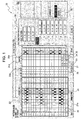
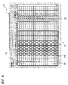
- Fig. 6 illustrates an example of the setting of the weaving pattern information. Specifically, Fig. 6 shows the setting conditions of the weaving pattern information displayed on a display window of a display unit included in a pattern editing device.
- the pattern editing device may be a built-in display device provided on the loom, of which display contents are editable, such as a display device having a touch-panel type display portion, or an external personal computer that is separate from the loom.
- shedding patterns for the shedding device In the left portion of a display window 20 in Fig. 6 are shown shedding patterns for the shedding device, the shedding patterns being one of the items included in the weaving pattern information.
- the example of the setting of the shedding patterns shown in Fig. 6 corresponds to a case where a weaving operation is to be performed using 12 heald frames (first to twelfth heald frames in that order from the cloth fell).
- Each shedding pattern includes drive modes of the heald frames for a corresponding one of weaving cycles.
- the shedding patterns are set for one repeat of a weave structure and are set in correspondence to total steps starting from Step No. 1 (i.e. the first weaving cycle in one repeat of the weave structure).
- each shedding pattern corresponds to one step, i.e.
- total steps refers to the number of weaving cycles (i.e. the number of picks) in one repeat of a weave structure, and in the example shown in Fig. 6, the total steps correspond to 1000 picks.
- the left portion of the display window 20 has a setting display section 21 which includes a plurality of cells 21a arranged in a matrix and shows shedding patterns.
- a display section 22 having numerical values that indicate weaving step numbers.
- Each of the weaving step numbers in the display section 22 not only corresponds to a shedding pattern but also to weaving pattern information.
- numerical values 32 above the setting display section 21 indicate heald frames (first to twentieth heald frames) that correspond to the cells 21a. Since the set shedding patterns in the example shown in Fig. 6 are for weaving using the first to twelfth heald frames, the cells 21a that correspond to the thirteenth to twentieth heald frames in the setting display section 21 are in a non-display mode.
- the corresponding shedding pattern is set such that the cells 21a corresponding to the designated heald frames are displayed in different display modes depending on whether the heald frames are to be positioned at an uppermost position or a lowermost position at the time of warp shedding in that weaving step.
- the display window 20 displays other weaving pattern information to the right of the setting display section 21.
- the weaving pattern information includes the type (color) of weft thread to be inserted in each weaving step, the weft density, and pile forming information that constitutes a pile weaving pattern.
- pile pattern information (P) which is a piece of pile forming information, is set in a setting display section 23 given a reference character "P" thereabove.
- the pile pattern information (P) is shown in the following manner: "3 2L-1F” or "4 2L-2F".
- the first value "3" in “3 2L-1F” indicates the number of pile picks.
- the second value “2L” indicates the number of loose picks, meaning that the number of loose picks is 2 picks.
- the third value “1F” indicates the number of fast picks, meaning that the number of fast picks is 1 pick.
- "3 2L-1F” represents one pile forming cycle consisting of a total of three picks, i.e.
- the display window 20 shown in Fig. 6 can also be used as, for example, an editing/setting window.
- the display window 20 may be configured such that information can be input to the cells in the setting display sections.
- the setting process of the weaving pattern information can be implemented by inputting information to the cells in correspondence to the weaving steps.
- this input process is implemented manually by an operator through the pattern editing device.
- the setting process of the weaving pattern information involves inputting information to the cells in a one-by-one fashion in correspondence to the weaving steps.
- pile forming information such as "3 2L-1F” and "4 2L-2F" is input to the cells in a one-by-one fashion.
- the pile forming information contains information related to the number of pile picks. If the pile forming information indicates that the number of pile picks is "3", the same information will always be set for three weaving steps. Regardless of the fact that the same information is simply required to be input for consecutive weaving steps, the same information has to be input one by one to the cells that correspond to these consecutive weaving steps in the conventional art. This input process is extremely troublesome. In addition, since this process needs to be performed for all the pile weave portions in one repeat of the weave structure, the process requires a large number of inputs, thus requiring too much time and effort.
- the possibility of an input error is considered to be low if there is only one kind of pile forming information to be set for the pile weave portions in one repeat of the weave structure.
- a mixture of different kinds of pile forming information needs to be set, that is, if the pile weaving is to be performed with different numbers of pile picks in one repeat of the weave structure, there is a high possibility of an input error in the setting process. For example, if the pile forming information indicates that the number of pile picks is four picks, the same information should be input for four weaving steps. However, there is a possibility that the same information is erroneously input for only three weaving steps, and the next pile forming information is subsequently input. In the case where such an input error occurs, the process for correcting the error will require even more time and effort.
- the present invention is directed to a pile loom that forms piles by driving pile forming elements through driving means that is independent of a main driving motor of the loom so as to change a relative position between a cloth fell of a woven cloth and a beating position, the pile forming elements being driven on the basis of a pile weaving pattern containing pile forming information set in correspondence with weaving steps, the pile forming information including the number of weaving cycles to be performed in one pile forming cycle.
- the present invention provides a pile-weaving-pattern editing device, which is provided for writing and editing the pile weaving pattern to be used in such a pile loom and includes controlling means having an automatic setting function.
- the controlling means Based on the pile forming information input for an arbitrary one of the weaving steps designated as a starting step, the controlling means automatically sets pile forming information corresponding to the input pile forming information for a plurality of the weaving steps that follows the starting step in accordance with the number of weaving cycles included in the input pile forming information.
- the term "input" is not limited to a case where information is directly input to a corresponding setting section, but may include a case where the setting section is set in a selected state and a desired piece of information is selected from a plurality of pieces of preliminarily set information so that the selected piece of information is set in the setting section.
- the setting sections may be selectable through another input window and information may be input to a selected one of the setting sections through that window so that the information can be set in that setting section.
- the controlling means automatically sets pile forming information corresponding to the input pile forming information for a plurality of the weaving steps that follow the starting step in accordance with the number of weaving cycles included in the pile forming information. Accordingly, when inputting pile forming information that indicates the number of pile picks is n picks, an operator only needs to input the pile forming information for the first weaving step of one pile forming cycle consisting of n picks. For the remaining weaving steps corresponding to (n - 1) picks, the controlling means automatically sets pile forming information corresponding to the pile forming information input by the operator.
- the number of inputs to be performed by the operator is reduced to 1/n or less, and the input process of the pile forming information for the n-pick weaving steps is properly implemented. Accordingly, this significantly reduces the time and effort required for the input process of the pile forming information performed by the operator.
- Figs. 1 to 3 illustrate an embodiment of the invention.
- Fig. 1 shows a setting display window 20 to which weaving pattern information can be input. Sections in Fig. 1 that are equivalent to those in the above description are given the same reference numerals, and descriptions of those sections will not be repeated.
- the pile loom to which the present invention is applied is of a cloth-shifting type.
- the pile loom is not limited to a cloth-shifting-type pile loom, and may include a pile loom of a type in which the beating position is shiftable with respect to a fixed cloth fell.
- setting display sections 23, 24, 25, 26 are provided to the right of the setting display section 21 in which shedding patterns are set.
- weaving pattern information other than the shedding patterns can be input.
- information related to the type (color) of weft thread to be inserted in each weaving step and information related to the weft density (density) are set as weaving pattern information.
- the pile weaving pattern being one of the items included in the weaving pattern information in the present invention is constituted by pile forming information set in the setting display sections 23, 24, 25.
- the pile pattern information (P) being one of the items included in the pile forming information, is set in the setting display section 23 given a reference character "P" thereabove.
- Examples of the pile pattern information (P) are [3 2L-1F], [4 3L-1F], [4 2L-2F], and [5 3L-2F].
- the pile forming information includes cloth-fell position information (L) which is information related to the relative position between the cloth fell CF and the beating position.
- this cloth-fell position information (L) is input to the setting display section 25 given a reference character "L” thereabove.
- pile step information (S) for one pile forming cycle is displayed in Fig. 1. This pile step information (S) is set in the setting display section 24 given a reference character "S" thereabove.
- the setting display sections 23, 24, 25 respectively have cells 23a, 24a, 25a, which correspond to the weaving step numbers shown in the leftmost display section 22 on the setting display window 20.
- the cells 23a, 24a, 25a have information set therein in correspondence to the weaving steps.
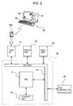
- Fig. 2 illustrates an external personal computer 30 serving as a pattern editing device that is separate from the pile loom.
- the weaving pattern information is set using the personal computer 30 and is set in a setting device 40 of the loom by means of a memory card MC.
- the personal computer 30 includes a main computer unit 31, a display 33 serving as a display unit, and a keyboard 35 serving as an input unit.
- the main computer unit 31 has a program installed therein for writing and editing the weaving pattern information. Accordingly, in this embodiment, the main computer unit 31 corresponds to controlling means according to the present invention.
- the setting device 40 in the loom includes a central processing unit (which will be referred to as a "CPU” hereinafter) 41, an input/output port (which will be referred to as an “I/O port” hereinafter) 42 connected to the CPU 41, and a storage unit 43.
- the I/O port 42 in the setting device 40 is connected to a display unit 45, an input unit 46, and a card interface (which will be referred to as a "card I/F” hereinafter) 47, which are provided in the loom.
- the weaving pattern information written in the personal computer 30 and stored in the memory card MC is read into the CPU 41 via the card I/F 47 and the I/O port 42 and is stored into the storage unit 43.
- the weaving pattern information stored in the storage unit 43 can be displayed on the display unit 45 by operating the input unit 46 to send a display command from the input unit 46 to the CPU 41 via the I/O port 42.
- the CPU 41 Based on the weaving pattern information stored in the storage unit 43, the CPU 41 outputs setting information of the weaving pattern information to controllers of the devices in the loom that are involved with weaving. For example, based on the set pile weaving pattern, the pile forming information can be output to the pile controller 48. Furthermore, based on the set shedding pattern, the set color, and the set density, the setting information can be output to a shed controller for driving the shedding device, a weft-insertion controller for controlling the weft insertion, and a take-up controller for controlling the density, although none of these controllers are shown in the drawings.
- an operator operates the personal computer 30 to display a new setting display window 20 on the display 33. It is assumed that the setting display section 21 and the setting display sections 23 to 26 in the setting display window 20 are in a blank state.
- the operator then begins the setting process of the weaving pattern information including information related to the shedding patterns, the types of weft threads to be inserted in the weaving steps, the densities, and the pile weaving pattern.
- the description of the setting process of the information related to the shedding patterns, the weft types, and the densities will be omitted below.
- the operator first operates the personal computer 30 so that the main computer unit 31 serving as controlling means executes the program for editing the pile weaving pattern.
- the cells 23a, 24a, 25a in the setting display sections 23, 24, 25 are set in a state such that pile forming information can be input thereto.
- a cursor 27 for selecting the cells 23a, 24a, 25a is displayed.
- the operator then puts the cursor 27 on one of the cells 23a in the setting display section 23 that corresponds to Step No. 1, which is the starting step, so that pile forming information for Step No. 1 can be input to that cell 23a.
- the operator confirms that the cell 23a corresponding to the starting step is selected and inputs pile pattern information (P) to that cell 23a.
- the cursor 27 can be moved arbitrarily to a desired position using, for example, cursor keys on the keyboard 35.
- a plurality of pieces of usable pile pattern information (P) is preliminarily set, and the pile pattern information pieces (P) are given the numbers 0 to 9, which are displayed in a display section 28.
- This is intended to facilitate the input process of the pile pattern information (P).
- the pile pattern information (P) can be input to a corresponding cell 23a by operating a numeric key on the keyboard 35 so that the pile pattern information piece (P) corresponding to the input numerical value is input to that cell 23a.
- the controlling means 31 when the operator inputs the pile pattern information (P) for the starting step, the controlling means 31 performs an automatic setting process of pile pattern information (P) for the number of pile picks (for example, n picks) included in the input pile pattern information (P).
- the controlling means 31 automatically sets the same pile pattern information (P) in the (n - 1) cells 23a that follow the input cell 23a.
- the controlling means 31 determines that the number of pile picks is three picks from that pile pattern information (P) and executes a program for automatically setting the same [3 2L-1F] pile pattern information (P) in the cells 23a for the two picks following the input cell 23a.
- the [3 2L-1F] pile pattern information (P) input by the operator is set in the three cells 23a for three consecutive picks including the input cell 23a, which is the state shown in Fig. 1.
- the controlling means 31 executes a program for automatically setting the same pile pattern information (P) in the cells 23a for the three consecutive picks following the input cell 23a.
- the operator for an input process of n-pile-pick pile pattern information (P), the operator only needs to input the pile pattern information (P) to the first cell 23a of the n consecutive cells 23a to which the same pile pattern information (P) is to be input.
- the controlling means 31 then automatically sets the same pile pattern information (P) for the remaining (n - 1) cells 23a. Consequently, this reduces the number of input operations to be performed by the operator and ensures that the input process is performed properly for the number of pile picks included in the pile pattern information (P).
- the controlling means 31 moves the cursor 27 to a cell 23a that follows the automatically set cells 23a, and waits in a standby state.
- the controlling means 31 automatically sets the same pile pattern information (P) in the cells 23a corresponding to Step No. 2 and Step No. 3.
- the controlling means 31 moves the cursor 27 to the cell 23a corresponding to Step No. 4 and waits in a standby state. Accordingly, the cursor 27 is moved automatically to the next cell that is subject to the next input process.
- the input process of the pile pattern information (P) can be performed continuously without having to perform an operation for moving the cursor 27.
- the pile forming information also includes the cloth-fell position information (L) and the pile step information (S) in addition to the pile pattern information (P), which are also set automatically.
- the controlling means 31 simultaneously with the automatic setting process of the pile pattern information (P), the controlling means 31 also automatically sets the cloth-fell position information (L) in the corresponding cells in the setting display section 25 for the corresponding weaving steps, and step numbers for the number of pile picks starting from 1 as the pile step information (S) in the corresponding cells in the setting display section 24.
- the cloth-fell position information (L) is information related to the position of the cloth fell CF relative to the beating position in a cloth-shifting-type pile loom and indicates a cloth-fell position at a beating point at each weaving step in one pile forming cycle, the beating point being a time point at which the inserted weft thread is beaten against the cloth fell in that weaving step. This implies that the cloth-fell position information for a fast-pick weaving step indicates 0 mm.
- a plurality of pieces of cloth-fell position information (L) is set as distance values from the beating position to the cloth fell CF in a separate database (not shown).
- cloth-fell position information pieces (L) are given numbers starting from 1 (for example, 1: 0 mm, 2: 10 mm, 3: 12 mm, and so on). Each of the cells 25a in the setting display section 25 is given one of the numbers that represents the cloth-fell position (i.e. the distance from the beating position).
- [1: 0 mm] is a fixed cloth-fell position information piece (L) that corresponds to fast-pick weaving.
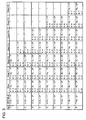
- the controlling means 31 has a database shown in Fig. 3 set and stored therein.
- the controlling means 31 executes a program for automatically setting the pile forming information in accordance with this database.
- the controlling means 31 in a first step (Step), sets "1" in section S (setting display section 24) of the same step number and "2" in section L (setting display section 25) of the same step number based on the fact that [3 2L-1F] is input in section P (setting display section 23).
- the controlling means 31 sets the same [3 2L-1F] pile pattern information (P) in the cell of section P of the subsequent step number, and sets "2" in section S of the same step number and "2" in section L of the same step number.
- the controlling means 31 sets the same [3 2L-1F] pile pattern information (P) in section P of the subsequent step number, and sets "3" in section S of the same step number and "1" in section L of the same step number. This completes the program (No. 0 in the database shown in Fig. 3).
- the program is similarly executed on the basis of the database shown in Fig. 3, whereby the pile forming information is set automatically.
- Each numerical value to be set in section L in the database is appropriately selected in accordance with the weaving conditions from another database having the cloth-fell position information (L) set therein.
- the controlling means 31 has a data checking function for checking whether the pile pattern information (P) set in the above-described manner is set properly.
- This data checking function for the set pile pattern information (P) is executed by operating an data-check enter button 29 provided on the right side of the setting display window 20 or by operating a designated data-check enter key provided on the keyboard 35.
- the same pile pattern information (P) should always be consecutively set for the number of pile picks included in the information (P). Consequently, the checking process of the pile pattern information (P) involves checking whether the same pile pattern information (P) is set consecutively for the number of pile picks for each pile forming cycle so as to determine whether the setting is proper or improper.
- the checking process of the pile pattern information (P) can be implemented by, for example, allowing the controlling means 31 to execute the following program.
- the present invention is not limited to the above-described case.
- the present invention can be employed for editing an already existing pile weaving pattern or for correcting a written pile weaving pattern.
- Fig. 4A illustrates another embodiment of the present invention, in which a stored pile weaving pattern that has been previously set and used is read out and edited so that the edited pile weaving pattern can be used again.
- additional weaving steps are added to an already existing pile weaving pattern for the number of pile picks included in additionally inserted pile forming information.
- the same automatic setting process as in the previous embodiment can be implemented.
- the present embodiment is not limited to the above case where the pile forming information is set after the operator has added the additional weaving steps.
- the operator may send a command to "add [pile pattern information (P)] to Step No. X" so that the controlling means 31 automatically adds additional weaving steps and sets the pile forming information.
- the automatic setting function can be similarly applied to another embodiment shown in Fig. 4B where an already existing pile weaving pattern is subject to a partial change.
- This embodiment shown in Fig. 4B is not limited to a case where already set pile forming information as shown is deleted once and is then replaced with new pile forming information.
- the already set pile forming information can be changed by writing new information over the already set information.
- the controlling means 31 may be equipped with an automatic weaving-step adding function to compensate for an imbalance between the number of pile picks included in the input pile forming information and the number of weaving steps that can be input.
- This function can be implemented by, for example, allowing the controlling means 31 to execute the following program.
- the automatic weaving-step adding function described above is also effective for error correction in a case where an error is found in the setting during the data checking process of the pile pattern information (P). Specifically, with regard to pile forming information with the number of pile picks being n picks, n pieces of the same information should be set. However, if there are only (n - 1) pieces of pile forming information set, the aforementioned automatic weaving-step adding function can be used for the correcting process, thereby facilitating the correcting process.
- the input process of the pile pattern information (P) is implemented by using the cursor 27 to designate a starting step in the above embodiment
- the present invention is not limited to this technique.
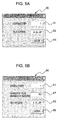
- the starting step can be designated through a setting window 50 that is provided separate from the setting display window 20 of the above embodiment.
- pile pattern information (P) to be input can also be set through this setting window 50.
- the controlling means 31 may input the pile pattern information (P) in the setting display window 20 for the designated starting step.
- a step number to be designated as a starting step can be input to a starting-step setting section 51 on the setting window 50, and pile pattern information (P) for the starting step can be input to a setting section 53.
- the controlling means 31 sets the pile pattern information (P) input to the setting section 53 in one of the cells 23a in the setting display section 23 that corresponds to the designated starting step. Subsequently, the automatic setting process of the pile pattern information (P) described in the above embodiment is implemented.
- the input process of the pile pattern information (P) for a starting step is performed for every starting step in the above embodiment, the present invention is not limited to this technique.
- the input process of the pile pattern information (P) for a starting step may be performed only a designated number of times by the controlling means 31.
- Fig. 5B shows a setting window 60 that is provided separate from the setting display window 20.
- the setting window 60 has setting sections 61 and 63 to which the first starting step and pile pattern information (P) are respectively input.
- the setting window 60 also has a setting section 67 to which the number of piles, i.e. the number of repeats, is input.
- the controlling means 31 inputs the pile pattern information (P) input in the setting section 63 into one of the cells 23a of the setting display section 23 that corresponds to the designated first starting step input in the setting section 61, and then performs the automatic setting process of the pile pattern information (P) described in the above embodiment.
- the controlling means 31 similarly inputs the pile pattern information (P) in the cell 23a that corresponds to the subsequent starting step, which is a cell 23a that follows the cells 23a that have underwent the automatic setting process described above.
- the controlling means 31 repeats the automatic setting process of the pile pattern information (P) described in the above embodiment and the input process of the pile pattern information (P) for the starting steps for the designated number of repeats input in the setting section 67.
- the controlling means 31 is given a function for repeating the input process of the pile pattern information (P) for the starting steps for a designated number of times, whereby the setting process of the pile pattern information (P) for a plurality of pile forming cycles can be performed automatically in one operation.
- the cloth-fell position information pieces (L) are preliminarily set in correspondence with the number of steps from the starting step.
- the cloth-fell position information pieces (L) set for these weaving steps may similarly be set for weaving steps of the subsequent pile forming cycle by the controlling means 31.
- the controlling means 31 may refer to the cloth-fell position information pieces (L) set for the weaving steps (Step Nos. 1 to 3) of the previous pile forming cycle having the same pile pattern information (P) ([3 2L-1F]) set therefor so as to set the same information pieces (L) in the cells 25a that correspond to Step Nos. 4 to 6.
Landscapes
- Engineering & Computer Science (AREA)
- Textile Engineering (AREA)
- Looms (AREA)
Applications Claiming Priority (1)
| Application Number | Priority Date | Filing Date | Title |
|---|---|---|---|
| JP2006186149A JP4942408B2 (ja) | 2006-07-06 | 2006-07-06 | パイル製織パターン編集装置 |
Publications (1)
| Publication Number | Publication Date |
|---|---|
| EP1876272A1 true EP1876272A1 (de) | 2008-01-09 |
Family
ID=38068484
Family Applications (1)
| Application Number | Title | Priority Date | Filing Date |
|---|---|---|---|
| EP07008872A Withdrawn EP1876272A1 (de) | 2006-07-06 | 2007-05-02 | Vorrichtung zum Bearbeiten von Webmustern für Florgewebe |
Country Status (3)
| Country | Link |
|---|---|
| EP (1) | EP1876272A1 (de) |
| JP (1) | JP4942408B2 (de) |
| CN (1) | CN101100781B (de) |
Families Citing this family (3)
| Publication number | Priority date | Publication date | Assignee | Title |
|---|---|---|---|---|
| DE102013219942A1 (de) * | 2013-10-01 | 2015-04-02 | Lindauer Dornier Gesellschaft Mit Beschränkter Haftung | Verfahren und Vorrichtung zum Aufbringen von Kräften und Bewegungen auf Kettfäden einer Webmaschine |
| JP7159063B2 (ja) * | 2019-01-22 | 2022-10-24 | 津田駒工業株式会社 | パイル織機における起動制限方法及び装置 |
| JP7702998B2 (ja) * | 2023-10-06 | 2025-07-04 | ヴィクラム クリシュナ デヴァラージ | 超長パイル高さがある速乾タオルを生成する方法 |
Citations (4)
| Publication number | Priority date | Publication date | Assignee | Title |
|---|---|---|---|---|
| FR2523602A1 (fr) * | 1982-03-22 | 1983-09-23 | Staeubli Ag | Procede et dispositif pour etablir de nouveaux dessins de tissu et supports de donnees |
| US5016183A (en) * | 1988-09-13 | 1991-05-14 | Computer Design, Inc. | Textile design system and method |
| EP0878571A1 (de) * | 1997-05-14 | 1998-11-18 | Kabushiki Kaisha Toyoda Jidoshokki Seisakusho | Schusseintragskontrollvorrichtung mit Schussidentifikationsanlage für Frottierwebmaschine |
| JPH11350303A (ja) * | 1998-06-02 | 1999-12-21 | Toyota Autom Loom Works Ltd | 織機における製織パターン確認装置 |
Family Cites Families (5)
| Publication number | Priority date | Publication date | Assignee | Title |
|---|---|---|---|---|
| JPS62268851A (ja) * | 1986-05-14 | 1987-11-21 | 津田駒工業株式会社 | 多色織機の経緯組織同期確認装置 |
| JPH0551835A (ja) * | 1991-08-13 | 1993-03-02 | Ricoh Co Ltd | 先染ドビー織物の表面柄パターン作成装置 |
| JP3348882B2 (ja) * | 1992-08-11 | 2002-11-20 | 株式会社リコー | 先染ドビー織物の表面柄パターン作成装置 |
| US5518037A (en) * | 1993-09-13 | 1996-05-21 | Kabushiki Kaisha Toyoda Jidoshokki Seisakusho | Cloth fell displacement in a terry loom |
| CN1475944A (zh) * | 2003-06-29 | 2004-02-18 | 浙江大学银河自动化有限公司 | 织物花形设计方法及数据存储装置 |
-
2006
- 2006-07-06 JP JP2006186149A patent/JP4942408B2/ja active Active
-
2007
- 2007-05-02 EP EP07008872A patent/EP1876272A1/de not_active Withdrawn
- 2007-05-25 CN CN 200710104524 patent/CN101100781B/zh active Active
Patent Citations (4)
| Publication number | Priority date | Publication date | Assignee | Title |
|---|---|---|---|---|
| FR2523602A1 (fr) * | 1982-03-22 | 1983-09-23 | Staeubli Ag | Procede et dispositif pour etablir de nouveaux dessins de tissu et supports de donnees |
| US5016183A (en) * | 1988-09-13 | 1991-05-14 | Computer Design, Inc. | Textile design system and method |
| EP0878571A1 (de) * | 1997-05-14 | 1998-11-18 | Kabushiki Kaisha Toyoda Jidoshokki Seisakusho | Schusseintragskontrollvorrichtung mit Schussidentifikationsanlage für Frottierwebmaschine |
| JPH11350303A (ja) * | 1998-06-02 | 1999-12-21 | Toyota Autom Loom Works Ltd | 織機における製織パターン確認装置 |
Also Published As
| Publication number | Publication date |
|---|---|
| JP4942408B2 (ja) | 2012-05-30 |
| CN101100781A (zh) | 2008-01-09 |
| CN101100781B (zh) | 2011-03-16 |
| JP2008013876A (ja) | 2008-01-24 |
Similar Documents
| Publication | Publication Date | Title |
|---|---|---|
| US8165712B2 (en) | Loom, in particular a ribbon loom | |
| EP1876272A1 (de) | Vorrichtung zum Bearbeiten von Webmustern für Florgewebe | |
| EP1849897A1 (de) | Vorrichtung fürs Einstellen von Fachbildungsmuster für eine Webmaschine | |
| JPS58169539A (ja) | 織成意匠図およびデ−タキヤリヤを造るための方法および装置 | |
| JPS5841932A (ja) | 織機の経糸開口監視装置 | |
| KR20060050914A (ko) | 직기에 있어서의 설정값을 설정하는 방법 | |
| JP2006249593A (ja) | 繊維機械の情報表示装置 | |
| EP1439250B1 (de) | Webmaschine mit einer Funktion zur Vermeidung von Schussstreifen | |
| CN101082148B (zh) | 织机的误运转防止装置 | |
| EP2065494A1 (de) | Verfahren zur automatischen Ersetzung von Garnen in einer Schäranlage | |
| CN102899782B (zh) | 织机的织造方法和织造装置 | |
| EP3686332B1 (de) | Verfahren und vorrichtung zur startbeschränkung einer frottierwebmaschine | |
| JP2643454B2 (ja) | ジェットルームにおける織成条件設定方法 | |
| CN101058913B (zh) | 在织机中用背面织造形成织物的方法和装置 | |
| JP4339217B2 (ja) | 設定値決定装置 | |
| EP1808517A2 (de) | Anzeigeeinstellvorrichtung zum Einstellen von selektiven Betriebsmodi für Webelemente einer Webmaschine | |
| JP5189737B2 (ja) | 織機の開口装置、及びその開口装置を使用した織機における織付け方法 | |
| EP1580308B1 (de) | Startsteuervorrichtung und Startsteuerverfahren für eine Webmaschine | |
| CN102899783B (zh) | 织机的织造方法和织造装置 | |
| JP2886616B2 (ja) | 織機の制御方法および装置 | |
| EP1798321B1 (de) | Verfahren zur Steuerung einer Webmaschine | |
| EP3831990B1 (de) | Spinnmustereinstellvorrichtung für eine spinnmaschine | |
| WO2006016757A1 (en) | Process for preparing patterned fabric | |
| JPS6262958A (ja) | 織機の緯糸選択装置 | |
| JPH0913242A (ja) | 織機の運転制御方法 |
Legal Events
| Date | Code | Title | Description |
|---|---|---|---|
| PUAI | Public reference made under article 153(3) epc to a published international application that has entered the european phase |
Free format text: ORIGINAL CODE: 0009012 |
|
| AK | Designated contracting states |
Kind code of ref document: A1 Designated state(s): AT BE BG CH CY CZ DE DK EE ES FI FR GB GR HU IE IS IT LI LT LU LV MC MT NL PL PT RO SE SI SK TR |
|
| AX | Request for extension of the european patent |
Extension state: AL BA HR MK YU |
|
| AKX | Designation fees paid | ||
| STAA | Information on the status of an ep patent application or granted ep patent |
Free format text: STATUS: THE APPLICATION IS DEEMED TO BE WITHDRAWN |
|
| 18D | Application deemed to be withdrawn |
Effective date: 20080710 |
|
| REG | Reference to a national code |
Ref country code: DE Ref legal event code: 8566 |