EP1876281A1 - Tambour pour machine à laver ou sèche-linge - Google Patents
Tambour pour machine à laver ou sèche-linge Download PDFInfo
- Publication number
- EP1876281A1 EP1876281A1 EP06425468A EP06425468A EP1876281A1 EP 1876281 A1 EP1876281 A1 EP 1876281A1 EP 06425468 A EP06425468 A EP 06425468A EP 06425468 A EP06425468 A EP 06425468A EP 1876281 A1 EP1876281 A1 EP 1876281A1
- Authority
- EP
- European Patent Office
- Prior art keywords
- basket
- band
- wall
- interruption
- areas
- Prior art date
- Legal status (The legal status is an assumption and is not a legal conclusion. Google has not performed a legal analysis and makes no representation as to the accuracy of the status listed.)
- Granted
Links
- 238000005406 washing Methods 0.000 title claims abstract description 33
- 238000001035 drying Methods 0.000 title description 3
- 230000002787 reinforcement Effects 0.000 claims description 7
- 238000005452 bending Methods 0.000 claims description 5
- 230000003247 decreasing effect Effects 0.000 claims description 4
- 230000007704 transition Effects 0.000 claims description 2
- 230000000694 effects Effects 0.000 description 7
- 230000010355 oscillation Effects 0.000 description 7
- 230000003116 impacting effect Effects 0.000 description 5
- 230000036961 partial effect Effects 0.000 description 5
- 229910000831 Steel Inorganic materials 0.000 description 4
- 238000007373 indentation Methods 0.000 description 4
- 239000010959 steel Substances 0.000 description 4
- 230000009467 reduction Effects 0.000 description 3
- 238000007792 addition Methods 0.000 description 2
- 238000005553 drilling Methods 0.000 description 2
- 239000007788 liquid Substances 0.000 description 2
- 229910001220 stainless steel Inorganic materials 0.000 description 2
- 239000010935 stainless steel Substances 0.000 description 2
- 239000006096 absorbing agent Substances 0.000 description 1
- 230000009471 action Effects 0.000 description 1
- 230000000295 complement effect Effects 0.000 description 1
- 230000008878 coupling Effects 0.000 description 1
- 238000010168 coupling process Methods 0.000 description 1
- 238000005859 coupling reaction Methods 0.000 description 1
- 230000001419 dependent effect Effects 0.000 description 1
- 238000007654 immersion Methods 0.000 description 1
- 239000012535 impurity Substances 0.000 description 1
- 230000001788 irregular Effects 0.000 description 1
- 230000002427 irreversible effect Effects 0.000 description 1
- 230000000670 limiting effect Effects 0.000 description 1
- 238000000034 method Methods 0.000 description 1
- 238000002156 mixing Methods 0.000 description 1
- 230000004048 modification Effects 0.000 description 1
- 238000012986 modification Methods 0.000 description 1
- 230000002829 reductive effect Effects 0.000 description 1
- 230000035939 shock Effects 0.000 description 1
- 239000000725 suspension Substances 0.000 description 1
- 230000002195 synergetic effect Effects 0.000 description 1
Images




Classifications
-
- D—TEXTILES; PAPER
- D06—TREATMENT OF TEXTILES OR THE LIKE; LAUNDERING; FLEXIBLE MATERIALS NOT OTHERWISE PROVIDED FOR
- D06F—LAUNDERING, DRYING, IRONING, PRESSING OR FOLDING TEXTILE ARTICLES
- D06F37/00—Details specific to washing machines covered by groups D06F21/00 - D06F25/00
- D06F37/02—Rotary receptacles, e.g. drums
- D06F37/04—Rotary receptacles, e.g. drums adapted for rotation or oscillation about a horizontal or inclined axis
-
- D—TEXTILES; PAPER
- D06—TREATMENT OF TEXTILES OR THE LIKE; LAUNDERING; FLEXIBLE MATERIALS NOT OTHERWISE PROVIDED FOR
- D06F—LAUNDERING, DRYING, IRONING, PRESSING OR FOLDING TEXTILE ARTICLES
- D06F25/00—Washing machines with receptacles, e.g. perforated, having a rotary movement, e.g. oscillatory movement, the receptacle serving both for washing and for centrifugally separating water from the laundry and having further drying means, e.g. using hot air
-
- D—TEXTILES; PAPER
- D06—TREATMENT OF TEXTILES OR THE LIKE; LAUNDERING; FLEXIBLE MATERIALS NOT OTHERWISE PROVIDED FOR
- D06F—LAUNDERING, DRYING, IRONING, PRESSING OR FOLDING TEXTILE ARTICLES
- D06F58/00—Domestic laundry dryers
- D06F58/02—Domestic laundry dryers having dryer drums rotating about a horizontal axis
- D06F58/04—Details
Definitions
- the present invention relates to a basket for a washing machine, dryer, or washer-dryer.
- the perforated basket which is intended to accommodate the laundry to be washed, is rotatably arranged within a tank containing the lye. Due to the rotational movement of the basket, the laundry is agitated and caused to spin in the lye, and the lye is carried upwards by the rotating basket, from where it falls on the laundry which results to be completely immersed and soaked, such that the impurities are transferred to the washing and rinsing lye.
- the basket usually consists of a rear wall by means of which the basket is secured within the washing machine, a front wall defining a loading opening through which it is possible to gain access to the interior of the basket and a side wall being generally cylindrical and perforated to allow the lye exchange between the tank and the interior of the basket.
- the side wall is usually formed from a steel sheet with two opposite longitudinal edges and two opposite transversal edges, which is folded about a longitudinal axis of the basket to form this cylinder and the transversal edges of which are connected to each other to keep the cylindrical shape, whereas the longitudinal edges are connected to respective outer edges of the rear and front walls to form the basket.
- New solutions are thus sought for positioning and orienting the blades in order to avoid these problems.
- a blade orientation other than the traditional one causes incompatibility problems between the shape of the blade root and the shape of the side wall and would oblige the manufacturers of washing machines and dryers to manage a range of various dragging blades according to various basket shapes and sizes.
- the general aim of the present invention is to provide a basket having such characteristics as to reconcile the requirements that have not been met or have been only partially met by the known solutions, and to the detriment of other requirements.
- the main object of the present invention is to provide a basket combining a high structural rigidity (against the deformations of the basket) with the possibility of allowing a different placement and orientation of the blades as compared with traditional ones without the requirement of arranging a range of various blades for various baskets.
- a further object of the present invention is to avoid the problem of local instability (snap through) of the side wall at the dragging blades.
- a further object of the present invention is to provide the basket with a shape that is fully consistent with what facilitates the achievement of said main objects and is further suitable to reduce the lye volume that is on the tank bottom, and which cannot be used for washing due to the safety distance between the basket and the tank.
- a loading basket for a washing machine, washer-dryer, dryer and the like comprising:
- Fig. 1 is a schematic sectional view, according to a vertical middle plane, of a washing machine provided with a basket according to an embodiment of the invention
- FIG. 2 is a partial cross-sectional view of a basket according to an embodiment of the invention.
- FIG. 3 is a cut-away perspective view of a basket according to an embodiment
- FIG. 4 is a side view of a basket according to an embodiment of the invention.
- Fig. 5 is a cross-sectional view of the basket from Fig. 4;
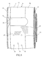
- Fig. 6 is a perspective view of the basket from Fig. 4;
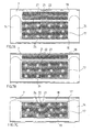
- Fig. 7A, 7B, 7C are partial views of the side wall of the basket according to an embodiment of the invention as developed in a hypothetical development plane.
- FIG. 8 is a partial sectional view of the side wall of a basket according to an embodiment of the invention.
- a front-loading washing machine with biased-axis tank is schematically shown in Fig. 1.
- the washing machine which is generally designated with 1
- the washing machine comprises a cabinet 2, a tank 3 being housed therein, which consists of a generally cylindrical body, either made of plastic or stainless steel, with either biased or horizontal longitudinal axis X (as shown in Fig. 1).
- the tank 3 is coupled to the cabinet 2 by means of known means, which comprise shock absorbers and suspension springs, which are not shown in order to avoid burdening the drawing.
- the tank 3 is provided with a front aperture 5, having a generally round shape, which can be closed by means of a porthole being frontally hinged to the cabinet 2 and not shown, as known per se.
- a basket 6 is housed rotatably about the axis X, for the laundry to be accommodated therein to be washed and/or dried.
- the basket 6 comprises a side wall 7, a rear or bottom wall 8 and a front wall 9.
- the walls 7, 8 and 9 define an inner space 10 intended to accommodate the laundry to be washed and/or dried.
- the front wall 9 of the basket 6 is a stainless steel or plastic ring, with an aperture 11 having a generally round shape, which is placed such as to match the aperture 5 of the tank 3 to provide access to the inner space 10 to load/unload the laundry.
- the rear or bottom wall 8 of the basket 6 is preferably a substantially plane, centrally drawn, steel disk, being concave towards the outside of the basket.
- a support hub 4 for the basket In the middle of the rear wall 8 of the basket 6, there is mounted a support hub 4 for the basket, the basket being operatively connected therethrough to motor means (not shown), which control the rotation of the same about the longitudinal axis X.
- the side wall 7 of the basket is preferably obtained from a flat steel sheet, which is bent such as to form an approximately rotational surface about a longitudinal central axis, being coincident with the longitudinal axis X of the tank 3 when in use.
- the coupling of the bottom 8 and front 9 walls to the side wall 7 is preferably provided by folding two end tracts of the sheet being the side wall 7, such as to give a C-shaped profile to the steel plate at both ends thereof.
- the bottom 8 and front 9 walls are shaped such as to define, at the outer edges thereof, profiles matching the C-shaped profile formed at both end tracts of the side wall 7.
- the basket 6 further comprises one or more, preferably three, dragging blades 12 being arranged on the side wall 7 and projecting to the inside 10 of the basket.
- the side wall 7 comprises a substantially cylindrical and/or truncated cone-shaped wall portion 13 (such as cylindrical, truncated cone-shaped or mixed cylindrical-truncated cone shaped or mixed cylindrical - cylindrical with different diameters or mixed truncated cone-shaped with step or inverted tapering).
- the "continuous" cylindrical and/or truncated-cone shape of the wall portion 13 is interrupted by one or more approximately plane interruption areas 14 extending from a rear area close to the rear wall 8 to the vicinity of the front wall 9 and wherein the dragging blades 12 are fixed to the side wall of the basket at these interruption areas 14.
- the approximately plane shape of the interruption areas allows the blades 12 to be positioned and oriented as desired, without requiring any modification to the connection root in order to adapt the same to the three-dimensionally curved shapes of the prior art baskets.
- the same approximately plane shape implies a synergy effect relative to the mechanical strength of the basket, because the plane area of the side wall can be elastically flexed (to a certain restricted extent) due to the laundry tangent force on the blades, without the occurrence of buckling events that are typical on arc-shaped structures (such as snap through).
- the side wall 7 is shaped such that the interruption areas 14 approximately lie in a plane intersecting the cylindrical and/or truncated cone-shape of the wall portion 13 and border on adjacent continuity cylindrical and/or truncated cone-shaped areas 15 of the wall portion 13 along a folding line 16 substantially without steps or large transition areas.
- the radius of the side wall 7 relative to the longitudinal axis X of the basket coincides with the corresponding radiuses both in the continuity area 15 and in the interruption area 14.
- the approximately interruption area 14 has a slight concavity as seen from the inside of the basket. Due to this (though slight) concavity, the interruption areas 14 provide an initial shape or deformation state that is substantially complementary to an actual deformation thereof caused by the centrifuge force of the laundry mass on the side wall. Thereby, the deformations of the basket under extreme stress can be well controlled, for example during the spin cycle, thus avoiding the occurrence of unplanned and maybe irreversible deformations.
- the interruption areas 14 are advantageously produced by means of cold expansion of the side wall 7 from a substantially cylindrical plate ring, such that the interruption areas 14 have a greater bending radius than and the same sign as the bending radius/es of the adjacent cylindrical and/or truncated cone-shaped continuity areas 15.
- the wall portion 13 comprises a main annular band 17, preferably cylindrical, and a cylindrical or truncated cone-shaped front annular band 18 which is arranged between the main band 17 and the front wall 9 of the basket, wherein the main band 17 has a greater average diameter than the average diameter of the front band 18 such that the barycentre of the inner volume being defined by the basket is shifted to the rear wall 8.
- the barycentre of the basket inner volume is in the rear half thereof, thus resulting in the fact that the prevailing laundry mass and the prevailing part of the centrifugal force by the latter also act in the rear half of the basket closer to the support point thereof. This contributes to a reduction in the width of the oscillations of the rotating basket.
- the interruption area/s is/are advantageously formed as being approximately plane such as to overlap both the main band 17 and the front band 18.
- the main band 17 has a substantially cylindrical shape, except for the approximately plane interruption areas 14, and that the front band 18 has, on the other hand, a substantially truncated-cone shape with a diameter decreasing towards the front wall 9, except for the approximately plane interruption areas 14. Due to the main cylindrical band that is enlarged relative to the front band, one obtains a maximum exploitation of the depth of the washing tank and thus the lye volume in the rear areas of the tank-basket assembly in which the width of the basket oscillations is reduced and a sufficient safety distance in the front area of the basket opposite the support point thereof, where on the contrary the oscillation width is maximum.
- the main cylinder-front cone combination is particularly suitable for the optimum exploitation of the lye volume accommodated within the tank 3, since the reduction in the diameter of the front band to the front wall 9 of the basket adapts the shape thereof (in the moment of maximum oscillation width) to the shape of the tank, thus resulting in the front band 18 of the basket being deeply immersed in the lye throughout the length thereof, without the front edge of the basket impacting against the tank wall.
- the wall portion 13 can comprise a further rear annular band 19 arranged between the main annular band 17 and the rear wall 8 of the basket and having an average diameter lower than the average diameter of the main band.
- the rear band 19 is preferably substantially truncated cone-shaped with a diameter decreasing towards the rear wall 8. This allows providing, for example, a basket in which the rear and front walls have the same external diameter and in which the enlarged main band can be obtained by means of cold expansion of the initially cylindrical side wall.
- the front band 18 has an extension in the longitudinal direction of the basket which is greater than the longitudinal extension of the rear band 19 and the main band 17 has an extension in the longitudinal direction of the basket which is greater than the longitudinal extension of the front band 18 and preferably of both rear 19 and front 18 bands.
- the approximately plane interruption areas are substantially limited to the area required for connecting the blade to the side wall of the basket. It is thus advantageous that these interruption areas are provided along a more or less wide strip substantially extending from the rear wall of the basket to the front wall or at least to the vicinity thereof.
- this interruption area allows any desired orientation of the blades, such as oblique relative to the longitudinal axis X, this interruption area does not require to be formed oblique, rather it can be provided parallel to the projection of the longitudinal axis X on the side wall 7. This contributes to an easier and more accurate cold expansion method.
- the interruption area 14 thus preferably defines a substantially rectangular partial surface, and at the front band 18, the interruption area 14 defines a substantially parabolic partial surface, thus allowing the dragging blade 12 to be extended both in the main band and front band and to be orientated either parallel or biased relative to the longitudinal axis X of the basket.
- the interruption areas 14 are formed at radial reinforcement ribs 20 of the rear wall 8 of the basket, such that the folding line 16 defining the interruption area 14 provides an axial extension of the reinforcement from the radial ribs 20 through the side wall 7 to the vicinity of the front wall 9 of the basket.
- the basket comprises three interruption areas 14 that are spaced from each other at 120° angular pitch and arranged in alignment with three reinforcement ribs 20 of the rear wall 8.
- the basket is provided with a drilling that provides, in the side wall, a pattern of many small through holes 21 that are substantially equidistant from each other and suitable to allow the lye to flow from the tank to the basket, and vice versa.
- a drilling that provides, in the side wall, a pattern of many small through holes 21 that are substantially equidistant from each other and suitable to allow the lye to flow from the tank to the basket, and vice versa.
- Each of these small holes 21 is advantageously formed at the central vertex of a dome 22 thereof, which is for example formed by indentation, projecting to the outside of the basket.
- the drilled side wall 7 Due to the regular pattern of dome-shaped indentations 22 having 2 to 8 mm diameter, preferably 3 to 5 mm, and radially projecting to the outside of the basket, the drilled side wall 7 has a high rigidity and the edges of the small holes 21 result to be moved away from the laundry, such as to avoid an abrasive contact between the through holes 21 and the laundry.
- the perforation is preferably provided only on said wall portion 13, and particularly the main cylindrical band 17 and the truncated cone-shaped band 18.
- the approximately plane interruption areas 14 are substantially provided without perforations, in order to allow the blades to be placed and orientated as desired, without having to take into account the irregular surface profile due to the perforations.
- those areas immediately surrounding the folding line 26 and a folding line 23 being formed between the main band 17 and the front band 18 are preferably provided without perforations 21 and indentations such as to allow the relative folding 16, 23 to be carried out along continuous lines in an easier manner.
- the side wall 7, and particularly the main cylindrical band 17 comprises a plurality of rounded projections 24, which protrude within the basket.
- These rounded projections 24 are preferably provided without small through holes and have a much larger diameter than that of the small holes and domes thereof.
- the rounded projections also have a dome or cap shape (convex as seen from within the basket) which is obtained by means of indentation.
- These rounded projections 24 have a diameter ranging between 1cm and 3cm, preferably about 2cm, and a height ranging between about 1mm and 4mm, preferably 2mm, and exert a soft dragging effect on the laundry in contact with the side wall 7 of the basket 6.
- a particular arrangement of the rounded projections 24 unusually contributes to an improved washing effectiveness, particularly on delicate garments.
- This arrangement of the rounded projections 24 is shown in Fig. 7A, 7B and 7C and provides for a circumferential succession of individual groups of rounded projections 24 (in which each group advantageously comprises three projections 24) which define, in turn, an arrow-tip pattern, i.e. a triangular arrangement with the triangle vertex being oriented in the circumferential direction of the side wall 7.
- Fig. 7A, 7B and 7C show parts of the side wall 7 of baskets having different depths (or, in other words, longitudinal extensions), wherein the main band 17 preferably has the same longitudinal extension, whereas the longitudinal extension of the front band 18 having the shape of a truncated cone changes according to the total depth of the basket. In the case of Fig. 7C, this front band 18 is very shallow and not provided with drilling.
- This blade 12 has a bend along the longitudinal extension thereof, such as to give the laundry, in addition to the well known lifting movement, a further movement in the longitudinal direction of the basket. This greatly contributes to a better mixing of the laundry during washing and drying while preventing the individual items (particularly the delicate ones) from remaining for a long time in areas greatly exposed to the mechanical action of the basket.
- This curved blade 12 has, as is known, a plurality of holes 25 for the lye to pass therethrough, which is accumulated in the lower part of the tank and released when the blade is in a raised position.
- these holes 25 comprise a first set of holes arranged along a longitudinal ridge 26 of the blade and a second set of holes arranged at an (either front or rear) end of the blade 12 such as to enhance the feeding of lye within the basket in the vicinity of this end as compared with the remaining areas of the blade.
- the volume barycentre of the basket is shifted to the support point thereof, which implies a reduction in the width of the oscillations of the basket, with the load and number of revolutions being equal, which allows reducing the safety distance between the basket and the tank and thus a better exploitation of the lye contained within the washing tank. Furthermore, due to the mixed cylindrical-truncated cone shape of the basket, the latter emerges with an overall larger volume thereof in the lye without impacting against the wall of the washing tank.
- the present invention not only can be applied to washing machines with biased-axis tanks, such as those in the example described above, but also to washing machines with horizontal axis, washer-dryers, and dryers.
Landscapes
- Engineering & Computer Science (AREA)
- Textile Engineering (AREA)
- Main Body Construction Of Washing Machines And Laundry Dryers (AREA)
Priority Applications (3)
| Application Number | Priority Date | Filing Date | Title |
|---|---|---|---|
| EP06425468A EP1876281B1 (fr) | 2006-07-06 | 2006-07-06 | Tambour pour machine à laver ou sèche-linge |
| US11/822,257 US7752872B2 (en) | 2006-07-06 | 2007-07-03 | Basket for washing machine, washer-dryer, dryer and the like |
| RU2007125422/12A RU2431705C2 (ru) | 2006-07-06 | 2007-07-05 | Барабан для стиральной машины, моечной машины с сушильной камерой или сушильной камеры |
Applications Claiming Priority (1)
| Application Number | Priority Date | Filing Date | Title |
|---|---|---|---|
| EP06425468A EP1876281B1 (fr) | 2006-07-06 | 2006-07-06 | Tambour pour machine à laver ou sèche-linge |
Publications (2)
| Publication Number | Publication Date |
|---|---|
| EP1876281A1 true EP1876281A1 (fr) | 2008-01-09 |
| EP1876281B1 EP1876281B1 (fr) | 2012-10-10 |
Family
ID=37307220
Family Applications (1)
| Application Number | Title | Priority Date | Filing Date |
|---|---|---|---|
| EP06425468A Ceased EP1876281B1 (fr) | 2006-07-06 | 2006-07-06 | Tambour pour machine à laver ou sèche-linge |
Country Status (3)
| Country | Link |
|---|---|
| US (1) | US7752872B2 (fr) |
| EP (1) | EP1876281B1 (fr) |
| RU (1) | RU2431705C2 (fr) |
Cited By (3)
| Publication number | Priority date | Publication date | Assignee | Title |
|---|---|---|---|---|
| CN108866941A (zh) * | 2018-07-16 | 2018-11-23 | 海信(山东)冰箱有限公司 | 一种滚筒洗衣机提升筋及滚筒洗衣机 |
| CN109154124A (zh) * | 2016-08-26 | 2019-01-04 | 松下知识产权经营株式会社 | 滚筒式洗衣机和滚筒式干燥机 |
| WO2021143607A1 (fr) * | 2020-01-17 | 2021-07-22 | 青岛海尔滚筒洗衣机有限公司 | Tambour interne et machine à laver le linge |
Families Citing this family (8)
| Publication number | Priority date | Publication date | Assignee | Title |
|---|---|---|---|---|
| DE602006017056D1 (de) * | 2006-07-06 | 2010-11-04 | Candy Spa | Trommel für eine Waschmaschine, einen Waschtrockner und dergleichen |
| US8887540B2 (en) * | 2010-07-28 | 2014-11-18 | Bsh Bosch Und Siemens Hausgeraete Gmbh | Laundry drum for a laundry treatment machine |
| JP5479277B2 (ja) * | 2010-09-01 | 2014-04-23 | パナソニック株式会社 | 脱水装置 |
| RU2516147C1 (ru) * | 2012-09-28 | 2014-05-20 | Федеральное государственное бюджетное образовательное учреждение высшего профессионального образования "Южно-Российский государственный университет экономики и сервиса" (ФГБОУ ВПО "ЮРГУЭС") | Стиральная машина барабанного типа |
| USD722212S1 (en) * | 2012-11-05 | 2015-02-03 | Samsung Electronics Co., Ltd. | Drum for washing machine |
| USD720902S1 (en) * | 2012-11-26 | 2015-01-06 | Samsung Electronics Co., Ltd. | Drum for washing machine |
| EP3412823B1 (fr) * | 2017-06-08 | 2022-03-30 | LG Electronics Inc. | Tambour de machine à laver |
| KR102711550B1 (ko) * | 2019-06-27 | 2024-09-27 | 엘지전자 주식회사 | 세탁기 및 그 제조 방법 |
Citations (5)
| Publication number | Priority date | Publication date | Assignee | Title |
|---|---|---|---|---|
| DE1144226B (de) * | 1959-04-23 | 1963-02-28 | Siemens Elektrogeraete Gmbh | Waschmaschinentrommel |
| EP0806513A2 (fr) * | 1996-05-11 | 1997-11-12 | Samsung Electronics Co., Ltd. | Machine à laver |
| WO2001061098A2 (fr) * | 2000-02-16 | 2001-08-23 | BSH Bosch und Siemens Hausgeräte GmbH | Tambour de lave-linge |
| DE10260023B3 (de) * | 2002-12-19 | 2004-01-22 | Miele & Cie. Kg | Waschmaschinentrommel mit Schröpfrippen und Verfahren zur Herstellung des Mantels einer solchen Waschmaschinentrommel |
| US20040244438A1 (en) * | 2001-07-28 | 2004-12-09 | North John Herbert | Washing machines |
Family Cites Families (23)
| Publication number | Priority date | Publication date | Assignee | Title |
|---|---|---|---|---|
| US2734368A (en) * | 1956-02-14 | richardson | ||
| US1020618A (en) * | 1911-07-12 | 1912-03-19 | Eli J Miller | Washing-machine. |
| US2286429A (en) * | 1938-10-29 | 1942-06-16 | Us Hoffman Machinery Corp | Washing machine |
| US2213453A (en) * | 1938-12-05 | 1940-09-03 | Cincinnati Butchers Supply Co | Washer |
| US2334025A (en) * | 1940-03-29 | 1943-11-09 | Leo M O'neill | Drier |
| US2343743A (en) * | 1941-04-10 | 1944-03-07 | Westinghouse Electric & Mfg Co | Cleaning apparatus |
| US2584070A (en) * | 1948-03-27 | 1952-01-29 | Braithwaite I & Son Eng Ltd | Machine for washing, dry cleaning, or garment dyeing |
| US2651509A (en) * | 1951-11-01 | 1953-09-08 | Sam M Hyman | Tumbler pad for drying machines |
| US2727315A (en) * | 1952-09-20 | 1955-12-20 | Gen Motors Corp | Domestic appliance |
| FR1190034A (fr) * | 1956-11-06 | 1959-10-08 | Hoover Ltd | Perfectionnements aux machines à laver |
| US3605281A (en) * | 1969-10-02 | 1971-09-20 | Philco Ford Corp | Clothes dryer |
| US3815258A (en) * | 1972-11-30 | 1974-06-11 | Whirlpool Co | Dryer having drum with two different diameters |
| DE2306873A1 (de) * | 1973-02-13 | 1974-08-22 | Licentia Gmbh | Trommel fuer waeschebehandlungsmaschinen |
| DE2363935C3 (de) * | 1973-12-20 | 1983-03-17 | Bosch-Siemens Hausgeräte GmbH, 7000 Stuttgart | Mantel für eine mantelbeschickbare Wäschetrommel einer Waschmaschine |
| US3938260A (en) * | 1974-12-11 | 1976-02-17 | Whirlpool Corporation | Adjustable baffle for appliance |
| JPS54104660A (en) * | 1978-02-06 | 1979-08-17 | Hitachi Ltd | Electric washing machine |
| NL8700715A (nl) * | 1987-03-26 | 1988-10-17 | Frank Maria Peter Lambrechts | Inrichting voor het behandelen van textiel. |
| JPH0263500A (ja) * | 1988-08-29 | 1990-03-02 | Toshiba Corp | 乾燥機 |
| SU1601250A2 (ru) * | 1988-12-26 | 1990-10-23 | Предприятие П/Я М-5612 | Стиральна машина |
| US4971449A (en) * | 1989-12-19 | 1990-11-20 | American Laundry Machinery Inc. | Drum type agitating and mixing machine |
| US5275026A (en) * | 1992-01-09 | 1994-01-04 | Staber Industries, Inc. | Clothes washing machine |
| JPH0647194A (ja) * | 1992-08-04 | 1994-02-22 | Sanyo Electric Co Ltd | ドラム式洗濯乾燥機 |
| JPH1176679A (ja) * | 1997-09-11 | 1999-03-23 | Sanyo Electric Co Ltd | ドラム式洗濯機 |
-
2006
- 2006-07-06 EP EP06425468A patent/EP1876281B1/fr not_active Ceased
-
2007
- 2007-07-03 US US11/822,257 patent/US7752872B2/en active Active
- 2007-07-05 RU RU2007125422/12A patent/RU2431705C2/ru not_active IP Right Cessation
Patent Citations (5)
| Publication number | Priority date | Publication date | Assignee | Title |
|---|---|---|---|---|
| DE1144226B (de) * | 1959-04-23 | 1963-02-28 | Siemens Elektrogeraete Gmbh | Waschmaschinentrommel |
| EP0806513A2 (fr) * | 1996-05-11 | 1997-11-12 | Samsung Electronics Co., Ltd. | Machine à laver |
| WO2001061098A2 (fr) * | 2000-02-16 | 2001-08-23 | BSH Bosch und Siemens Hausgeräte GmbH | Tambour de lave-linge |
| US20040244438A1 (en) * | 2001-07-28 | 2004-12-09 | North John Herbert | Washing machines |
| DE10260023B3 (de) * | 2002-12-19 | 2004-01-22 | Miele & Cie. Kg | Waschmaschinentrommel mit Schröpfrippen und Verfahren zur Herstellung des Mantels einer solchen Waschmaschinentrommel |
Cited By (3)
| Publication number | Priority date | Publication date | Assignee | Title |
|---|---|---|---|---|
| CN109154124A (zh) * | 2016-08-26 | 2019-01-04 | 松下知识产权经营株式会社 | 滚筒式洗衣机和滚筒式干燥机 |
| CN108866941A (zh) * | 2018-07-16 | 2018-11-23 | 海信(山东)冰箱有限公司 | 一种滚筒洗衣机提升筋及滚筒洗衣机 |
| WO2021143607A1 (fr) * | 2020-01-17 | 2021-07-22 | 青岛海尔滚筒洗衣机有限公司 | Tambour interne et machine à laver le linge |
Also Published As
| Publication number | Publication date |
|---|---|
| US20080006065A1 (en) | 2008-01-10 |
| EP1876281B1 (fr) | 2012-10-10 |
| RU2007125422A (ru) | 2009-01-10 |
| RU2431705C2 (ru) | 2011-10-20 |
| US7752872B2 (en) | 2010-07-13 |
Similar Documents
| Publication | Publication Date | Title |
|---|---|---|
| US7752872B2 (en) | Basket for washing machine, washer-dryer, dryer and the like | |
| RU2433214C2 (ru) | Барабан для стиральной машины, стирально-сушильной машины и тому подобное | |
| RU2402651C2 (ru) | Бытовой водопотребляющий прибор с рельефным бельевым барабаном | |
| EP1964960B1 (fr) | Machine à laver améliorant l'efficacité du lavage | |
| CN101089277B (zh) | 洗衣机及形成其滚筒的方法 | |
| EP2391759B1 (fr) | Machine à laver | |
| EP2987901B1 (fr) | Structure intégrée de cylindre interne et d'agitateur, machine à laver et procédé de lavage | |
| EP2000574B1 (fr) | Corps de cuve rotative et machine à laver de type à tambour doté de celui-ci | |
| EP2719808B1 (fr) | Machine à laver | |
| MX2008009891A (es) | Mejora en los rebordes de elevacion del tambor de una maquina lavadora de ropa. | |
| EP2053152B1 (fr) | Lave-linge ou sèche-linge doté d'un tambour avec éléments de relèvement amovibles | |
| EP2628839A1 (fr) | Machine à laver | |
| RU2413804C2 (ru) | Стиральная машина с фронтальной загрузкой | |
| JPH09173681A (ja) | 二重パルセーターを備えた洗濯機 | |
| EP1043440A2 (fr) | Plaque de lavage pour machine à laver le linge | |
| EP1619285B2 (fr) | Tambour pour machine à laver, sèche-linge, ou équivalent | |
| EP2580384B1 (fr) | Lave-linge | |
| EP2280108A1 (fr) | Machine à laver à chargement frontal | |
| US7428832B2 (en) | Drum washing machine | |
| US12559876B2 (en) | Drum for a washing machine and washing machine | |
| EP4640937A1 (fr) | Tambour pour machine à laver le linge, sèche-linge, lave-linge ou appareils similaires | |
| EP2065507B1 (fr) | Machine de blanchisserie | |
| KR20030055968A (ko) | 세탁기의 저수조 | |
| JP2025187805A (ja) | 洗濯機 | |
| WO2009095303A1 (fr) | Dispositif d'élévation pour machine à laver |
Legal Events
| Date | Code | Title | Description |
|---|---|---|---|
| PUAI | Public reference made under article 153(3) epc to a published international application that has entered the european phase |
Free format text: ORIGINAL CODE: 0009012 |
|
| AK | Designated contracting states |
Kind code of ref document: A1 Designated state(s): AT BE BG CH CY CZ DE DK EE ES FI FR GB GR HU IE IS IT LI LT LU LV MC NL PL PT RO SE SI SK TR |
|
| AX | Request for extension of the european patent |
Extension state: AL BA HR MK YU |
|
| 17P | Request for examination filed |
Effective date: 20080515 |
|
| 17Q | First examination report despatched |
Effective date: 20080612 |
|
| AKX | Designation fees paid |
Designated state(s): DE GB IT |
|
| GRAP | Despatch of communication of intention to grant a patent |
Free format text: ORIGINAL CODE: EPIDOSNIGR1 |
|
| GRAS | Grant fee paid |
Free format text: ORIGINAL CODE: EPIDOSNIGR3 |
|
| GRAA | (expected) grant |
Free format text: ORIGINAL CODE: 0009210 |
|
| AK | Designated contracting states |
Kind code of ref document: B1 Designated state(s): DE GB IT |
|
| RAP1 | Party data changed (applicant data changed or rights of an application transferred) |
Owner name: CANDY S.P.A. |
|
| REG | Reference to a national code |
Ref country code: GB Ref legal event code: FG4D |
|
| RIN1 | Information on inventor provided before grant (corrected) |
Inventor name: FUMAGALLI, SILVANO |
|
| REG | Reference to a national code |
Ref country code: DE Ref legal event code: R096 Ref document number: 602006032356 Country of ref document: DE Effective date: 20121206 |
|
| PLBE | No opposition filed within time limit |
Free format text: ORIGINAL CODE: 0009261 |
|
| STAA | Information on the status of an ep patent application or granted ep patent |
Free format text: STATUS: NO OPPOSITION FILED WITHIN TIME LIMIT |
|
| 26N | No opposition filed |
Effective date: 20130711 |
|
| REG | Reference to a national code |
Ref country code: DE Ref legal event code: R097 Ref document number: 602006032356 Country of ref document: DE Effective date: 20130711 |
|
| PGFP | Annual fee paid to national office [announced via postgrant information from national office to epo] |
Ref country code: IT Payment date: 20190709 Year of fee payment: 14 Ref country code: DE Payment date: 20190830 Year of fee payment: 14 |
|
| PGFP | Annual fee paid to national office [announced via postgrant information from national office to epo] |
Ref country code: GB Payment date: 20190719 Year of fee payment: 14 |
|
| REG | Reference to a national code |
Ref country code: DE Ref legal event code: R119 Ref document number: 602006032356 Country of ref document: DE |
|
| GBPC | Gb: european patent ceased through non-payment of renewal fee |
Effective date: 20200706 |
|
| PG25 | Lapsed in a contracting state [announced via postgrant information from national office to epo] |
Ref country code: GB Free format text: LAPSE BECAUSE OF NON-PAYMENT OF DUE FEES Effective date: 20200706 |
|
| PG25 | Lapsed in a contracting state [announced via postgrant information from national office to epo] |
Ref country code: DE Free format text: LAPSE BECAUSE OF NON-PAYMENT OF DUE FEES Effective date: 20210202 |
|
| PG25 | Lapsed in a contracting state [announced via postgrant information from national office to epo] |
Ref country code: IT Free format text: LAPSE BECAUSE OF NON-PAYMENT OF DUE FEES Effective date: 20200706 |