EP1876317A1 - Porte en sections - Google Patents
Porte en sections Download PDFInfo
- Publication number
- EP1876317A1 EP1876317A1 EP07008061A EP07008061A EP1876317A1 EP 1876317 A1 EP1876317 A1 EP 1876317A1 EP 07008061 A EP07008061 A EP 07008061A EP 07008061 A EP07008061 A EP 07008061A EP 1876317 A1 EP1876317 A1 EP 1876317A1
- Authority
- EP
- European Patent Office
- Prior art keywords
- door
- wicket
- closure
- lock
- leaf
- Prior art date
- Legal status (The legal status is an assumption and is not a legal conclusion. Google has not performed a legal analysis and makes no representation as to the accuracy of the status listed.)
- Granted
Links
- 230000000284 resting effect Effects 0.000 claims 1
- 238000007688 edging Methods 0.000 description 4
- 230000037431 insertion Effects 0.000 description 1
- 238000003780 insertion Methods 0.000 description 1
Images

Classifications
-
- E—FIXED CONSTRUCTIONS
- E05—LOCKS; KEYS; WINDOW OR DOOR FITTINGS; SAFES
- E05B—LOCKS; ACCESSORIES THEREFOR; HANDCUFFS
- E05B65/00—Locks or fastenings for special use
- E05B65/0021—Locks or fastenings for special use for overhead or roll-up doors, e.g. garage doors
-
- E—FIXED CONSTRUCTIONS
- E06—DOORS, WINDOWS, SHUTTERS, OR ROLLER BLINDS IN GENERAL; LADDERS
- E06B—FIXED OR MOVABLE CLOSURES FOR OPENINGS IN BUILDINGS, VEHICLES, FENCES OR LIKE ENCLOSURES IN GENERAL, e.g. DOORS, WINDOWS, BLINDS, GATES
- E06B3/00—Window sashes, door leaves, or like elements for closing wall or like openings; Layout of fixed or moving closures, e.g. windows in wall or like openings; Features of rigidly-mounted outer frames relating to the mounting of wing frames
- E06B3/32—Arrangements of wings characterised by the manner of movement; Arrangements of movable wings in openings; Features of wings or frames relating solely to the manner of movement of the wing
- E06B3/48—Wings connected at their edges, e.g. foldable wings
- E06B3/485—Sectional doors
-
- E—FIXED CONSTRUCTIONS
- E05—LOCKS; KEYS; WINDOW OR DOOR FITTINGS; SAFES
- E05C—BOLTS OR FASTENING DEVICES FOR WINGS, SPECIALLY FOR DOORS OR WINDOWS
- E05C19/00—Other devices specially designed for securing wings, e.g. with suction cups
- E05C19/10—Hook fastenings; Fastenings in which a link engages a fixed hook-like member
- E05C19/12—Hook fastenings; Fastenings in which a link engages a fixed hook-like member pivotally mounted around an axis
- E05C19/14—Hook fastenings; Fastenings in which a link engages a fixed hook-like member pivotally mounted around an axis with toggle action
-
- E—FIXED CONSTRUCTIONS
- E06—DOORS, WINDOWS, SHUTTERS, OR ROLLER BLINDS IN GENERAL; LADDERS
- E06B—FIXED OR MOVABLE CLOSURES FOR OPENINGS IN BUILDINGS, VEHICLES, FENCES OR LIKE ENCLOSURES IN GENERAL, e.g. DOORS, WINDOWS, BLINDS, GATES
- E06B3/00—Window sashes, door leaves, or like elements for closing wall or like openings; Layout of fixed or moving closures, e.g. windows in wall or like openings; Features of rigidly-mounted outer frames relating to the mounting of wing frames
- E06B3/70—Door leaves
- E06B2003/7057—Door leaves with little passing through doors
Definitions
- the invention relates to a sectional door with a door leaf formed from hinged door panels and arranged in a door opening of the door leaf wicket, wherein the wicket door panel constructed of a door leaf, whose lateral edges are formed as hinge side and hinge opposite side, and wherein the wicket on the hinge side is pivotally supported on the door leaf and fixed to the hinge opposite side by a door lock device on the door leaf in a door closed position.
- the door panel is typically vertically aligned.
- the panels of the door leaf are brought in lateral guide rails along an arc in a typically horizontal opening position.
- the wicket door allows passage through the sectional door without having to move the entire door leaf. It can be manually opened and closed and therefore be operated even in the event of a failure of a Torblattantriebes. Furthermore, wicket doors can be opened quickly and reliably in emergency situations, which is why sectional doors whose door leaves have a wicket door are particularly suitable for commercial use and for garages and halls which have no additional exit next to the sectional door.
- a sectional door with the feature described above is from the document DE 20 2005 007 416 U1 known.
- locking devices are provided, in each case on the Torblattinnenseite a horizontally displaceable latch on the wicket door and an associated latch receptacle is placed on the door leaf.
- the locking devices To allow easy insertion of the bolt in the bolt receptacle and especially in emergency situations, To allow quick opening, the locking devices must have a certain amount of play. The required play the locking devices has a negative impact on the burglary, because due to the remaining game easily burglary tools can be attached to the wicket.
- the invention has for its object to provide a sectional door with the features described above, in which both a secure closure and easy operation of the wicket door are guaranteed.
- the door lock device has at least one tension lock with a first and a second part, wherein a part is placed on a surface of the door leaf and the other part on an associated surface of the wicket, the parts having closure portions, the engage behind in the closed position of the clamping closure at its ends, and wherein the first part has a clamping mechanism with a latching in the closed position of the clamping closure and acting on the associated closure portion actuating lever.
- the tension lock formed from the first part and the second part is also characterized by a very easy operation.
- the door leaf may comprise a door frame formed from Zargensegmenten and the door panel composed of edging segments enclosure, each Zargensegment end is placed on an associated Torpaneel the Torblattes and each edging segment on an associated end of a door panel.
- the wicket door By a partial overlapping of door frame and enclosure a stop the wicket door can be set in the door closed position, preferably a door seal between the door frame and enclosure is arranged.
- the clamping lock in its closed position also exerts a force acting in the direction of door thickness on the door leaf of the wicket door, whereby the door seal is compressed and the air-tightness of the wicket door is increased.
- the wicket door in addition to the door lock device has a door lock with a lock box inserted laterally into the wicket door and a handle set and the door leaf has an associated strike plate.
- the wicket door In the open position of the tension lock or the tension locks of the door lock device, the wicket door can be opened and closed particularly easily by the door leaf inside and the door leaf outside by an operation of the door lock.
- the door closure device is brought into the closed position with the at least one tension lock.
- the wicket door from the door leaf outside is not open and it is achieved increased security against burglary.
- the door closure device for example, in the commercial sector, the wicket door at night and on weekends against unauthorized intrusion be secured.
- a door lock is particularly not required if the wicket is provided only as an emergency exit and does not have to be opened and closed by the Torblattau combinites.
- the clamping mechanism of the first part to a tension spring wherein the closure portion of the first part as an eyelet, hook or rigid bracket and the closure portion of the second part is formed as a counter hook.
- the eyelet, the hook or the rigid bracket is first placed on the closure portion of the second part, wherein the closure portions are brought into engagement by a closing movement of the actuating lever and engages the actuating lever against the force of the tension spring in the closed position.
- one of the closure portions is designed as a resilient bow and the other closure portion as a counter hook.
- the first part of the tension lock can be placed on the door leaf or the door leaf without restriction on the inside of the door leaf, the other part being placed on the door leaf or the door leaf accordingly. It is preferably provided that the amount and / or the direction of the clamping force acting in the closed position of the clamping closure is adjustable. Due to the adjustability of the clamping mechanism is a precise adjustment and adjustment of the lock according to the respective requirements possible.
- skirt segments may be provided with protruding cams, the cams being provided in each case in a closed wicket door engage a recess of an associated Zargensegmentes.
- the individual door panels can be fixed in the vertical direction and door thickness direction, wherein the wicket door is held perpendicular to it in the horizontal direction by the at least one tension lock play in the door opening.
- a bolt can also be provided, which engages on the underside of the wicket door in the locked state in an associated receptacle.
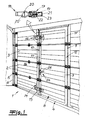
- FIG. 1 shows a sectional door 1 with a door leaf 3 formed from articulated door panels 2 and a wicket door 4 arranged in a door opening of the door leaf 3.
- the door leaf 3 with the wicket door 4 inserted therein is guided at its edges by rollers 5 in rails 6 brought in an opening movement along the rails 6 in a substantially horizontal opening position.
- the wicket door 4 has a door panel 8 made up of door panels 7, the vertical edges of the wicket door 4 being designed as a hinge side 9 and hinge opposite side 10.
- the door leaf 8 has an enclosure 12 constructed from edging segments 11, 11 ', and the door leaf 3 has a door frame 14 made up of frame segments 13.
- a door closure device formed from two tension locks 15 which fixes the wicket door 4 in a door closed position on the door leaf 3.
- the tension locks 15 each have a on the Torblattinnenseite 16 on the enclosure 12 mounted on the first part 17 and a mounted on the door frame 14 second part 18.
- the first part 17 has a tensioning mechanism 19 with an actuating lever 21 which engages in the closed position of the tension lock 15 and acts on an associated closure portion 20.
- the closure portion 20 is formed as an eyelet and engages in the closed position of the clamping closure 15 designed as a counter hook closure portion 20 'of the second part 18.
- the bias of the tension spring 22 is adjustable by a clamping nut 23.
- a door lock 24 is arranged with a lock case 25 inserted laterally into the wicket door 4 and with a handle set 26, wherein the door leaf 3 has an associated strike plate 27.
- the wicket door 4 can be actuated by the door leaf inner side 16 and by the door leaf outer side 28 by an actuation of the door lock 24.
- the closure device With the help of the closure device, the wicket door 4 can be reliably secured against unauthorized intrusion from the Torblattau builtseite. Despite the very good burglar protection, the fasteners 15 can be opened very easily in an emergency.
- Fig. 2 shows a horizontal section of an alternative embodiment of the invention in a plan view.
- the closure portion 20 of the attached to the band opposite side 10 of the wicket 4 on the enclosure 12 first part 17 of the tension lock 15 is formed as a resilient strap, wherein the closure portion 20 'of the associated, placed on the door frame 14 of the door leaf 3 second part 18 of the tension lock 15th is designed as a counter hook.
- In the door closed position is a projecting part 29 of the enclosure 12 on the hinge side 9 and on the hinge opposite side 10th via a door seal 30 on the door frame 14 at.
- the tension lock 15 is designed such that the wicket door 4 is pulled on the hinge opposite side 10 in the direction of the adjacent Torpaneele 2 of the door leaf 3 and the enclosure 12 is pressed against the door frame 14, wherein the door seal 30 is compressed.
- the tension lock 15 thus ensures in the closed position a very good burglar resistance and additionally also a largely airtight closure of the wicket door 4.
- the wicket door 4 is held on the hinge side 9 by door hinges 31 on the door leaf 3.
- the edging segments 11 'of the skirt 12 have on the band side 9 projecting cams 32 which engage in a recess of an associated Zargensegmentes 13 respectively.
- the wicket door 4 is fixed in the door thickness direction and in the vertical direction, wherein the wicket door 4 is held perpendicularly thereto in the horizontal direction along the extension of the door leaf 3 by the tension lock 15 tight.
- the wicket door with the door lock 24 can be opened and closed by the door leaf inner side 16 and the door leaf outer side 28.
Landscapes
- Engineering & Computer Science (AREA)
- Civil Engineering (AREA)
- Structural Engineering (AREA)
- Wing Frames And Configurations (AREA)
- Gates (AREA)
- Control Of Vending Devices And Auxiliary Devices For Vending Devices (AREA)
Applications Claiming Priority (1)
| Application Number | Priority Date | Filing Date | Title |
|---|---|---|---|
| DE102006030675A DE102006030675A1 (de) | 2006-07-04 | 2006-07-04 | Sektionaltor |
Publications (2)
| Publication Number | Publication Date |
|---|---|
| EP1876317A1 true EP1876317A1 (fr) | 2008-01-09 |
| EP1876317B1 EP1876317B1 (fr) | 2013-08-21 |
Family
ID=38657714
Family Applications (1)
| Application Number | Title | Priority Date | Filing Date |
|---|---|---|---|
| EP07008061.9A Not-in-force EP1876317B1 (fr) | 2006-07-04 | 2007-04-20 | Porte en sections |
Country Status (3)
| Country | Link |
|---|---|
| EP (1) | EP1876317B1 (fr) |
| DE (1) | DE102006030675A1 (fr) |
| ES (1) | ES2435406T3 (fr) |
Cited By (3)
| Publication number | Priority date | Publication date | Assignee | Title |
|---|---|---|---|---|
| EP2698495A3 (fr) * | 2012-08-10 | 2014-04-02 | Hörmann KG Brockhagen | Porte |
| EP4424969A1 (fr) | 2023-03-01 | 2024-09-04 | Condoor Group B.V. | Porte sectionnelle |
| EP4431693A1 (fr) | 2023-03-13 | 2024-09-18 | Condoor Group B.V. | Porte sectionnelle |
Families Citing this family (1)
| Publication number | Priority date | Publication date | Assignee | Title |
|---|---|---|---|---|
| DE102020116927A1 (de) | 2020-06-26 | 2021-12-30 | Alpha Deuren International Bv | Abschlusselement und Tor mit einem Abschlusselement |
Citations (2)
| Publication number | Priority date | Publication date | Assignee | Title |
|---|---|---|---|---|
| DE202005007416U1 (de) * | 2005-05-10 | 2005-09-15 | Hoermann Kg | Tor |
| DE102004047166A1 (de) * | 2004-09-29 | 2006-03-30 | Niewöhner Industrie GmbH + Co.KG | Sektionaltor mit Fluchttür |
Family Cites Families (2)
| Publication number | Priority date | Publication date | Assignee | Title |
|---|---|---|---|---|
| US5271649A (en) * | 1992-12-31 | 1993-12-21 | Southco, Inc. | Over center draw latch with lock bolt action |
| US5478125A (en) * | 1994-06-09 | 1995-12-26 | Southco, Inc. | Draw latch with catch having kick-out action |
-
2006
- 2006-07-04 DE DE102006030675A patent/DE102006030675A1/de not_active Withdrawn
-
2007
- 2007-04-20 ES ES07008061T patent/ES2435406T3/es active Active
- 2007-04-20 EP EP07008061.9A patent/EP1876317B1/fr not_active Not-in-force
Patent Citations (2)
| Publication number | Priority date | Publication date | Assignee | Title |
|---|---|---|---|---|
| DE102004047166A1 (de) * | 2004-09-29 | 2006-03-30 | Niewöhner Industrie GmbH + Co.KG | Sektionaltor mit Fluchttür |
| DE202005007416U1 (de) * | 2005-05-10 | 2005-09-15 | Hoermann Kg | Tor |
Cited By (8)
| Publication number | Priority date | Publication date | Assignee | Title |
|---|---|---|---|---|
| EP2698495A3 (fr) * | 2012-08-10 | 2014-04-02 | Hörmann KG Brockhagen | Porte |
| EP2698495B1 (fr) | 2012-08-10 | 2018-01-31 | Hörmann KG Brockhagen | Porte |
| EP3296500A1 (fr) * | 2012-08-10 | 2018-03-21 | Hörmann KG Brockhagen | Porte |
| EP3296500B1 (fr) | 2012-08-10 | 2018-10-24 | Hörmann KG Brockhagen | Porte |
| EP4424969A1 (fr) | 2023-03-01 | 2024-09-04 | Condoor Group B.V. | Porte sectionnelle |
| NL2034246B1 (en) | 2023-03-01 | 2024-09-09 | Condoor Group B V | Sectional door |
| EP4431693A1 (fr) | 2023-03-13 | 2024-09-18 | Condoor Group B.V. | Porte sectionnelle |
| NL2034332B1 (en) | 2023-03-13 | 2024-09-24 | Condoor Group B V | Sectional door |
Also Published As
| Publication number | Publication date |
|---|---|
| EP1876317B1 (fr) | 2013-08-21 |
| DE102006030675A1 (de) | 2008-01-10 |
| ES2435406T3 (es) | 2013-12-19 |
Similar Documents
| Publication | Publication Date | Title |
|---|---|---|
| DE2611359A1 (de) | Treibstangenverschluss, insbesondere fuer zweifluegelige feuerschutztueren | |
| DE19652601C1 (de) | Ent- und Verriegelung für eine einen Standflügel und einen Gangflügel aufweisende Tür | |
| EP1944446A2 (fr) | Dispositif destiné à fermer des fenêtres ou des portes | |
| EP1876317B1 (fr) | Porte en sections | |
| DE102017208059A1 (de) | Fenster oder Tür mit einbruchsicherer Kippöffnungsbegrenzung | |
| DE19917158C2 (de) | Mehrfachfunktions- und Sicherheitsrahmen für Fenster, Türen und sonstige bewegliche Flügel zum Verschließen von Öffnungen | |
| DE19916338A1 (de) | Sicherheitsvorrichtung für ein Fenster und Fenster mit einer solchen Sicherheitsvorrichtung | |
| DE69609988T2 (de) | Türsicherheitsvorrichtung | |
| EP2113624A2 (fr) | Dispositif de fixation de porte ou de fenêtre | |
| DE202016006592U1 (de) | Tür oder Fenstersicherung/ Einbruchschutz / Aufhebelsicherung für Doppelfenster oder Türen mit einem Anschlagpfosten | |
| EP0846825B1 (fr) | Dispositif de verrouillage pour un vantail de porte amovible dans un châssis | |
| EP0694667A1 (fr) | Elément coulissant, en particulier fenêtre ou porte | |
| DE4419309C1 (de) | Fenster- oder Türsicherung | |
| DE19745553A1 (de) | Schließvorrichtung | |
| DE10236707A1 (de) | Vorrichtung für eine Tür | |
| DE202008004659U1 (de) | Öffnungsbegrenzung für ein Fenster oder eine Tür | |
| DE3039406A1 (de) | Ausstellvorrichtung fuer drehkipp-fenster, -tueren o.dgl. | |
| DE60201616T2 (de) | Feststeller für Tür, Fenster dgl. mit treibstangenverschlussartigen Beschlag | |
| EP4242412B1 (fr) | Joint d'étanchéité doté d'une baguette d'étanchéité mobile à l'aide d'un mécanisme de mise en mouvement, le mécanisme de mise en mouvement étant actionnable au moyen d'un actionneur au moins partiellement pivotant | |
| DE102017007613B4 (de) | Ladensystem für Gebäudeöffnungen | |
| DE2914376C2 (de) | Zweiflügelige Tür mit Schloß-Einstecktaschen | |
| DE19715317A1 (de) | Einrichtung zum Sichern ineinander zur anlage gebrachter Teile von Objekten | |
| DE102015116173B3 (de) | Beschlagvorrichtung für ein Fenster mit einem Fensterflügel und einem Fensterrahmen sowie ein Fenster | |
| DE102007002634A1 (de) | Beschlag für ein Fenster oder eine Tür | |
| DE102023127523A1 (de) | Vorrichtung zum Öffnen eines Drehkippfensters |
Legal Events
| Date | Code | Title | Description |
|---|---|---|---|
| PUAI | Public reference made under article 153(3) epc to a published international application that has entered the european phase |
Free format text: ORIGINAL CODE: 0009012 |
|
| AK | Designated contracting states |
Kind code of ref document: A1 Designated state(s): AT BE BG CH CY CZ DE DK EE ES FI FR GB GR HU IE IS IT LI LT LU LV MC MT NL PL PT RO SE SI SK TR |
|
| AX | Request for extension of the european patent |
Extension state: AL BA HR MK YU |
|
| 17P | Request for examination filed |
Effective date: 20080202 |
|
| AKX | Designation fees paid |
Designated state(s): BE DE ES FR NL |
|
| GRAP | Despatch of communication of intention to grant a patent |
Free format text: ORIGINAL CODE: EPIDOSNIGR1 |
|
| GRAS | Grant fee paid |
Free format text: ORIGINAL CODE: EPIDOSNIGR3 |
|
| GRAA | (expected) grant |
Free format text: ORIGINAL CODE: 0009210 |
|
| AK | Designated contracting states |
Kind code of ref document: B1 Designated state(s): BE DE ES FR NL |
|
| REG | Reference to a national code |
Ref country code: DE Ref legal event code: R096 Ref document number: 502007012174 Country of ref document: DE Effective date: 20131017 |
|
| REG | Reference to a national code |
Ref country code: NL Ref legal event code: T3 |
|
| REG | Reference to a national code |
Ref country code: ES Ref legal event code: FG2A Ref document number: 2435406 Country of ref document: ES Kind code of ref document: T3 Effective date: 20131219 |
|
| PLBE | No opposition filed within time limit |
Free format text: ORIGINAL CODE: 0009261 |
|
| STAA | Information on the status of an ep patent application or granted ep patent |
Free format text: STATUS: NO OPPOSITION FILED WITHIN TIME LIMIT |
|
| 26N | No opposition filed |
Effective date: 20140522 |
|
| REG | Reference to a national code |
Ref country code: DE Ref legal event code: R097 Ref document number: 502007012174 Country of ref document: DE Effective date: 20140522 |
|
| REG | Reference to a national code |
Ref country code: DE Ref legal event code: R119 Ref document number: 502007012174 Country of ref document: DE |
|
| REG | Reference to a national code |
Ref country code: NL Ref legal event code: V1 Effective date: 20141101 |
|
| REG | Reference to a national code |
Ref country code: DE Ref legal event code: R119 Ref document number: 502007012174 Country of ref document: DE Effective date: 20141101 |
|
| REG | Reference to a national code |
Ref country code: FR Ref legal event code: ST Effective date: 20141231 |
|
| PG25 | Lapsed in a contracting state [announced via postgrant information from national office to epo] |
Ref country code: DE Free format text: LAPSE BECAUSE OF NON-PAYMENT OF DUE FEES Effective date: 20141101 |
|
| PG25 | Lapsed in a contracting state [announced via postgrant information from national office to epo] |
Ref country code: NL Free format text: LAPSE BECAUSE OF NON-PAYMENT OF DUE FEES Effective date: 20141101 Ref country code: FR Free format text: LAPSE BECAUSE OF NON-PAYMENT OF DUE FEES Effective date: 20140430 |
|
| PG25 | Lapsed in a contracting state [announced via postgrant information from national office to epo] |
Ref country code: ES Free format text: LAPSE BECAUSE OF NON-PAYMENT OF DUE FEES Effective date: 20070421 Ref country code: BE Free format text: LAPSE BECAUSE OF FAILURE TO SUBMIT A TRANSLATION OF THE DESCRIPTION OR TO PAY THE FEE WITHIN THE PRESCRIBED TIME-LIMIT Effective date: 20140430 |
|
| PG25 | Lapsed in a contracting state [announced via postgrant information from national office to epo] |
Ref country code: ES Free format text: LAPSE BECAUSE OF NON-PAYMENT OF DUE FEES Effective date: 20140421 |