EP1876320A1 - Emetteur de barrières lumineuses ajustable - Google Patents
Emetteur de barrières lumineuses ajustable Download PDFInfo
- Publication number
- EP1876320A1 EP1876320A1 EP07008656A EP07008656A EP1876320A1 EP 1876320 A1 EP1876320 A1 EP 1876320A1 EP 07008656 A EP07008656 A EP 07008656A EP 07008656 A EP07008656 A EP 07008656A EP 1876320 A1 EP1876320 A1 EP 1876320A1
- Authority
- EP
- European Patent Office
- Prior art keywords
- light barrier
- transmitting element
- adjusting
- barrier transmitter
- justierlichtstrahl
- Prior art date
- Legal status (The legal status is an assumption and is not a legal conclusion. Google has not performed a legal analysis and makes no representation as to the accuracy of the status listed.)
- Withdrawn
Links
Images


Classifications
-
- E—FIXED CONSTRUCTIONS
- E05—LOCKS; KEYS; WINDOW OR DOOR FITTINGS; SAFES
- E05F—DEVICES FOR MOVING WINGS INTO OPEN OR CLOSED POSITION; CHECKS FOR WINGS; WING FITTINGS NOT OTHERWISE PROVIDED FOR, CONCERNED WITH THE FUNCTIONING OF THE WING
- E05F15/00—Power-operated mechanisms for wings
- E05F15/40—Safety devices, e.g. detection of obstructions or end positions
- E05F15/42—Detection using safety edges
- E05F15/43—Detection using safety edges responsive to disruption of energy beams, e.g. light or sound
-
- E—FIXED CONSTRUCTIONS
- E05—LOCKS; KEYS; WINDOW OR DOOR FITTINGS; SAFES
- E05F—DEVICES FOR MOVING WINGS INTO OPEN OR CLOSED POSITION; CHECKS FOR WINGS; WING FITTINGS NOT OTHERWISE PROVIDED FOR, CONCERNED WITH THE FUNCTIONING OF THE WING
- E05F15/00—Power-operated mechanisms for wings
- E05F15/70—Power-operated mechanisms for wings with automatic actuation
- E05F15/73—Power-operated mechanisms for wings with automatic actuation responsive to movement or presence of persons or objects
- E05F15/74—Power-operated mechanisms for wings with automatic actuation responsive to movement or presence of persons or objects using photoelectric cells
-
- E—FIXED CONSTRUCTIONS
- E05—LOCKS; KEYS; WINDOW OR DOOR FITTINGS; SAFES
- E05F—DEVICES FOR MOVING WINGS INTO OPEN OR CLOSED POSITION; CHECKS FOR WINGS; WING FITTINGS NOT OTHERWISE PROVIDED FOR, CONCERNED WITH THE FUNCTIONING OF THE WING
- E05F15/00—Power-operated mechanisms for wings
-
- E—FIXED CONSTRUCTIONS
- E05—LOCKS; KEYS; WINDOW OR DOOR FITTINGS; SAFES
- E05F—DEVICES FOR MOVING WINGS INTO OPEN OR CLOSED POSITION; CHECKS FOR WINGS; WING FITTINGS NOT OTHERWISE PROVIDED FOR, CONCERNED WITH THE FUNCTIONING OF THE WING
- E05F15/00—Power-operated mechanisms for wings
- E05F15/40—Safety devices, e.g. detection of obstructions or end positions
- E05F15/42—Detection using safety edges
- E05F15/43—Detection using safety edges responsive to disruption of energy beams, e.g. light or sound
- E05F2015/434—Detection using safety edges responsive to disruption of energy beams, e.g. light or sound with cameras or optical sensors
- E05F2015/435—Detection using safety edges responsive to disruption of energy beams, e.g. light or sound with cameras or optical sensors by interruption of the beam
- E05F2015/436—Detection using safety edges responsive to disruption of energy beams, e.g. light or sound with cameras or optical sensors by interruption of the beam the beam being parallel to the wing edge
-
- E—FIXED CONSTRUCTIONS
- E05—LOCKS; KEYS; WINDOW OR DOOR FITTINGS; SAFES
- E05Y—INDEXING SCHEME ASSOCIATED WITH SUBCLASSES E05D AND E05F, RELATING TO CONSTRUCTION ELEMENTS, ELECTRIC CONTROL, POWER SUPPLY, POWER SIGNAL OR TRANSMISSION, USER INTERFACES, MOUNTING OR COUPLING, DETAILS, ACCESSORIES, AUXILIARY OPERATIONS NOT OTHERWISE PROVIDED FOR, APPLICATION THEREOF
- E05Y2400/00—Electronic control; Electrical power; Power supply; Power or signal transmission; User interfaces
- E05Y2400/10—Electronic control
- E05Y2400/50—Fault detection
-
- E—FIXED CONSTRUCTIONS
- E05—LOCKS; KEYS; WINDOW OR DOOR FITTINGS; SAFES
- E05Y—INDEXING SCHEME ASSOCIATED WITH SUBCLASSES E05D AND E05F, RELATING TO CONSTRUCTION ELEMENTS, ELECTRIC CONTROL, POWER SUPPLY, POWER SIGNAL OR TRANSMISSION, USER INTERFACES, MOUNTING OR COUPLING, DETAILS, ACCESSORIES, AUXILIARY OPERATIONS NOT OTHERWISE PROVIDED FOR, APPLICATION THEREOF
- E05Y2400/00—Electronic control; Electrical power; Power supply; Power or signal transmission; User interfaces
- E05Y2400/80—User interfaces
- E05Y2400/81—Feedback to user, e.g. tactile
- E05Y2400/818—Visual
- E05Y2400/822—Light emitters, e.g. light emitting diodes [LED]
-
- E—FIXED CONSTRUCTIONS
- E05—LOCKS; KEYS; WINDOW OR DOOR FITTINGS; SAFES
- E05Y—INDEXING SCHEME ASSOCIATED WITH SUBCLASSES E05D AND E05F, RELATING TO CONSTRUCTION ELEMENTS, ELECTRIC CONTROL, POWER SUPPLY, POWER SIGNAL OR TRANSMISSION, USER INTERFACES, MOUNTING OR COUPLING, DETAILS, ACCESSORIES, AUXILIARY OPERATIONS NOT OTHERWISE PROVIDED FOR, APPLICATION THEREOF
- E05Y2600/00—Mounting or coupling arrangements for elements provided for in this subclass
- E05Y2600/10—Adjustable
-
- E—FIXED CONSTRUCTIONS
- E05—LOCKS; KEYS; WINDOW OR DOOR FITTINGS; SAFES
- E05Y—INDEXING SCHEME ASSOCIATED WITH SUBCLASSES E05D AND E05F, RELATING TO CONSTRUCTION ELEMENTS, ELECTRIC CONTROL, POWER SUPPLY, POWER SIGNAL OR TRANSMISSION, USER INTERFACES, MOUNTING OR COUPLING, DETAILS, ACCESSORIES, AUXILIARY OPERATIONS NOT OTHERWISE PROVIDED FOR, APPLICATION THEREOF
- E05Y2600/00—Mounting or coupling arrangements for elements provided for in this subclass
- E05Y2600/40—Mounting location; Visibility of the elements
- E05Y2600/45—Mounting location; Visibility of the elements in or on the fixed frame
Definitions
- the present invention relates to an adjustable light barrier transmitter.
- Photocells with such an adjustable photocell transmitter are used in particular for controlling garage door drives, where they either enable the automatic control of the garage door drive or perform security functions.
- a light barrier In addition to a light barrier transmitter, which emits the main light beam of the light barrier, a light barrier usually also includes a receiver for receiving the light beam. To ensure proper operation of the photocell, the photocell transmitter must be adjusted after installation to align the photocell transmitter with the receiver. This often results in practice problems because the main light beam of the light barrier has a small opening angle of about +/- 5 °. These small opening angles are advantageous because this less unwanted reflections z. B. at the gate or the floor covering. Therefore, even smaller opening angles tend to be desirable. Due to these small opening angles, the light barrier transmitter and receiver must be aligned very precisely with one another which is made more difficult, in particular, by the fact that the optical axes are not recognizable. On the one hand, this is based on the fact that the main light beam usually consists of invisible infrared light and also the housing shape of the light barrier transmitter usually does not clearly indicate the optical axis.
- Object of the present invention is therefore to provide a light barrier transmitter and an adjustment available, which allow a simple and accurate adjustment.
- Such an adjustable light barrier transmitter in this case comprises an adjusting element which emits an adjustment light beam of light in the visible range, which runs parallel to the main light beam of the light barrier.
- the visible adjustment light beam makes it very easy to adjust the light barrier transmitter.
- the transmitting element which emits the main light beam, only needs to be adjusted until the Justierlichtstrahl incident on the predetermined position on the receiver.
- the adjusting element can be firmly connected to the transmitting element or else merely represent an assembly tool that is connected to the transmitting element only for adjusting the light barrier transmitter.
- the adjustable light beam has a smaller opening angle than the main light beam.
- the main light beam can be adjusted with great accuracy.
- the Justierlichtstrahl thereby has an opening angle of less than 1 °.
- the light spot generated by the Justierlichtstrahl is also clearly visible, because of the small opening angle also results in a great contrast.
- the Justierlichtstrahl is generated by a laser. This results in a particularly bright Justierlichtstrahl with a small opening angle, with the use of laser diodes, a cost-effective design is possible.
- the adjustable light barrier transmitter on a transmitting element for the main light beam on which the adjusting element can be attached is rotatable.
- the transmitting element can simply be turned into the correct position, in which it is precisely aligned with the receiving element.
- the Justierlichtstrahl is perpendicular to the axis of rotation of the transmitting element. This is particularly advantageous if the main light beam is perpendicular to the axis of rotation of the transmitting element, since so Justierlichtstrahl and main light beam at least with respect to the axis of rotation have the same orientation. If the main light beam, however, the axis of rotation shifted, and the Justierstrahl should be moved in the same way against the axis of rotation as the main light beam.
- the adjusting element can be plugged onto the transmitting element.
- the adjusting element is designed only as an assembly tool, which is attached only to adjust the light barrier to the transmitting element, this allows for easy attachment. If the adjusting element is used only as a mounting element, the production costs of the light barrier are reduced, since the same adjusting element can be used for adjusting many light barriers.
- the transmitting element is rotatably mounted in a mounting housing and advantageously, the mounting housing has recesses through which fastening means for fastening the adjusting element on the rotatable transmitting element can engage.
- the mounting housing protects the transmitter element from external influences such. B. bumps and also prevents a misalignment of the light barrier, while the recesses in the mounting housing allow to connect the adjusting element through the mounting housing with the rotatable transmitting element.
- the adjusting element comprises two pins, which can engage in recesses in the transmitting element, which are arranged on opposite sides of the axis of rotation of the transmitting element.
- the adjusting element is automatically aligned correctly on the axis of rotation of the transmitting element.
- the light barrier transmitter further advantageously has a locking element, with which the rotatable transmitting element can be fixed in the correct position against the mounting housing. It may also have limiting elements which limit the movement of the transmitting element in the fastening housing.
- the present invention further comprises an adjusting element for adjusting a light barrier transmitter which emits an alignment light beam of light in the visible range and which has connecting means with which it can be connected to a transmitting element emitting a main light beam so that the Justierlichtstrahl and the main light beam are parallel.
- Such an adjustment element is then usually used as an assembly tool for adjusting a light barrier transmitter as described above.
- the top and bottom surfaces and the side surfaces of such an adjustment element run parallel to the propagation direction of the Justierlichtstrahls, so that even without the laser, a simple alignment of the transmitting element possible is.
- this has the adjustment along the propagation direction of the Justierstrahls its longest dimension.
- the present invention comprises an adjustable light barrier transmitter with a main light beam emitting transmitting element having connecting means with which it can be connected to an Justierlichtstrahl emitting adjusting member so that the Justierlichtstrahl and the main light beam are parallel.
- an adjustable light barrier transmitter can then be adjusted in a simple manner with a usually a mounting tool performing adjustment.
- the transmitting element is rotatably mounted in a mounting housing and the mounting housing has recesses through which fastening means for fixing the adjusting element on the rotatable transmitting element can engage.
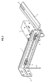
- FIG. 1 shows a first exemplary embodiment of the adjustable light barrier transmitter according to the invention with an adjusting element.
- the transmitting element for the main light beam is located in a mounting housing 1 and is rotatable about an axis of rotation 20.
- the mounting housing 1 has recesses 4, through which mounting pins 3 can engage the adjusting element 2 and can be pushed into non-seeing fastening receptacles in the transmitter element.
- the adjusting element 2 has substantially the shape of a ruler, that is, it consists essentially of an elongated plate. At the front end of this plate, a laser element 5 is arranged for generating the Justierlichtstrahls. The laser element 5 is inserted into the adjusting element 2 in such a way that the adjusting light beam runs in the plane of the adjusting element 2 parallel to its side edges. If the adjusting element 2 is connected to the rotatable transmitting element by the fastening pins 3, the transmitting element can already be roughly aligned without the laser.
- the transmitting element can be rotated with the aid of the adjusting element into the correct position by means of the adjusting beam, in which the transmitting element is precisely aligned with a receiving element.
- the recesses 4 in the mounting housing 1 correspond to circular arc pieces which are arranged on opposite sides of the rotation axis 20 about this. Through these recesses 4, the fastening pins 3 of the adjusting element 2 can grip, so that the transmitting element can be rotated together with the adjusting element until the mounting pins 3 abut the upper or lower edges of the recesses 4.
- separate stubble elements may also be provided, which limit the rotational movement of the transmitting element.
- the mounting housing 1 is arranged on a mounting rail 7, on which it is linearly displaceable. For this purpose, the mounting housing 1 on projecting elements 8, behind which edges of the mounting rail 7 can be pushed and with which the mounting housing 1 is mounted on the mounting rail 7. The leading to the transmitting element cable 6 is held by a clip member 9 on the mounting rail 7.
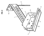
- FIG. 2 shows the embodiment in a perspective view from the front.
- the mounting housing 1 consists of a U-shaped bent metal sheet, wherein the axis of rotation 20 of the transmitting element 10 is rotatably mounted in recesses in opposite side surfaces of the U-shaped mounting housing 1.
- the fastening housing 1 can be pushed onto the fastening rail 7, while it is open on its front side, so that the main beam of the light barrier can be radiated unhindered by the transmitting element 10 to the front.
- the adjusting element 2 can now be connected to the transmitting element 10 by fastening pins 3 such that the adjusting beam emitted by the adjusting element is emitted parallel to the main beam of the light barrier emitted by the transmitting element 10. Both the adjustment beam and the main beam are in the embodiment perpendicular to the axis of rotation 20 of the transmitting element 10th
- the mounting rail 7 has a mounting bracket 12, with which they z. B. can be mounted on a wall.
- the cable 6 is guided via clip elements 11 on the mounting rail 7.
- the clip elements 11 have this in turn pins on which are pressed into recesses in the mounting rail 7 and are connected to this.
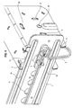
- FIG. 3 shows the same situation as in FIG. 2 from the rear. In particular, it is easy to see how the cable 6 is fastened by the clip elements 9 and 11 on the mounting rail 7.
- the clip element 9 has in pairs opposite Klipparme 17 whose inwardly tapered tips allow easy insertion of the cable between the Klipparme and which have barbs on its inner side, which prevent pulling out of the cable 6 from the clip element.
- the clip member 9 also has on its back pin, with which it can be pressed into recesses 15 in the mounting rail 7.
- the mounting rail 7, in addition to the centrally located recesses 15 further grooves 16 which extend above and below the holes 15 along the longitudinal axis of the rail and increase the stability.
- the mounting housing 1 has on its rear side projecting elements 8, which surround the upper and lower edges of the mounting rail and thus hold the mounting housing 1 to the mounting rail 7. Furthermore, the upper side of the housing also has an overhanging element 18. The mounting housing 1 is thereby linearly displaceable along the mounting rail 7.
- the mounting housing 1 is bent from a metal plate and so produced in a particularly simple manner.
- FIGs 5a and 5b now show the adjustable light transmitter according to the invention in a front view, wherein in Figure 5a, the transmitting element 10 is shown in its most downwardly inclined position and in Figure 5b in its most inclined upward position.
- the transmitting element 10 is rotatable about the axis of rotation 20 and in the correct position by the locking element 22 can be fixed.
- the locking element 22 in this case consists of a screw which can be screwed into the transmitting element 10 and runs in an arcuate recess 21. By abutting the screw 22 at the lateral edges of the recess 21, the rotation angle range of the transmitting element 10 is automatically limited.
- the transmitting element 10 can be fixed in this position by tightening the screw 22.
Landscapes
- Optical Communication System (AREA)
- Securing Globes, Refractors, Reflectors Or The Like (AREA)
Applications Claiming Priority (1)
| Application Number | Priority Date | Filing Date | Title |
|---|---|---|---|
| DE202006010483U DE202006010483U1 (de) | 2006-07-06 | 2006-07-06 | Justierbarer Lichtschrankensender |
Publications (1)
| Publication Number | Publication Date |
|---|---|
| EP1876320A1 true EP1876320A1 (fr) | 2008-01-09 |
Family
ID=38573468
Family Applications (1)
| Application Number | Title | Priority Date | Filing Date |
|---|---|---|---|
| EP07008656A Withdrawn EP1876320A1 (fr) | 2006-07-06 | 2007-04-27 | Emetteur de barrières lumineuses ajustable |
Country Status (5)
| Country | Link |
|---|---|
| US (1) | US20080016708A1 (fr) |
| EP (1) | EP1876320A1 (fr) |
| CN (1) | CN101101340A (fr) |
| DE (1) | DE202006010483U1 (fr) |
| RU (1) | RU2007125482A (fr) |
Cited By (1)
| Publication number | Priority date | Publication date | Assignee | Title |
|---|---|---|---|---|
| EP2880468B1 (fr) | 2012-08-06 | 2018-08-15 | Hörmann KG Antriebstechnik | Dispositif à grille de lumière, dispositif de sécurité à grille de lumière et portail à entraînement automatique équipé dudit dispositif de sécuité à grille |
Families Citing this family (5)
| Publication number | Priority date | Publication date | Assignee | Title |
|---|---|---|---|---|
| CN104021096B (zh) * | 2014-05-28 | 2017-10-27 | 深圳市信威电子有限公司 | 红外光栅单元件及组件 |
| DE102015016312A1 (de) * | 2014-12-16 | 2016-07-14 | Datalogic Ip Tech S.R.L. | Optische Einheit für ein optoelektronisches System |
| CN111053450A (zh) * | 2019-01-15 | 2020-04-24 | 上海爱餐机器人(集团)有限公司 | 智能炒菜机及其菜盘检测装置 |
| CN110916472A (zh) * | 2019-01-15 | 2020-03-27 | 上海爱餐机器人(集团)有限公司 | 智能炒菜机、菜盘检测装置及其红外对射传感器调节组件 |
| CN114070422B (zh) * | 2021-11-25 | 2023-03-21 | 湖北神狐时代云科技有限公司 | 一种信息网络安全设备用防电磁干扰装置 |
Citations (4)
| Publication number | Priority date | Publication date | Assignee | Title |
|---|---|---|---|---|
| US3752978A (en) * | 1971-02-04 | 1973-08-14 | Arrowhead Ets Inc | Photoelectric intrusion detector |
| US20020105430A1 (en) * | 2001-01-31 | 2002-08-08 | Williams Gerald H. | Self-aligning safety sensors |
| EP1233283A2 (fr) * | 2001-02-14 | 2002-08-21 | Leuze electronic GmbH + Co. | Dispositif optoélectronique |
| EP1394504A1 (fr) * | 2002-08-30 | 2004-03-03 | Sick AG | Rideau optique ou barrière optique |
Family Cites Families (3)
| Publication number | Priority date | Publication date | Assignee | Title |
|---|---|---|---|---|
| DE3513671C3 (de) * | 1985-04-16 | 1995-03-23 | Sick Optik Elektronik Erwin | Lichttaster |
| JPH11354831A (ja) * | 1998-06-10 | 1999-12-24 | Keyence Corp | 狭い角度特性の光軸付きエリアセンサ |
| DE102004008059A1 (de) * | 2004-02-19 | 2005-09-22 | Sick Ag | Lichtschranke oder Lichtgitter mit Ausrichthilfe |
-
2006
- 2006-07-06 DE DE202006010483U patent/DE202006010483U1/de not_active Expired - Lifetime
-
2007
- 2007-04-27 EP EP07008656A patent/EP1876320A1/fr not_active Withdrawn
- 2007-07-05 RU RU2007125482/12A patent/RU2007125482A/ru not_active Application Discontinuation
- 2007-07-05 US US11/825,243 patent/US20080016708A1/en not_active Abandoned
- 2007-07-05 CN CNA2007101275961A patent/CN101101340A/zh active Pending
Patent Citations (4)
| Publication number | Priority date | Publication date | Assignee | Title |
|---|---|---|---|---|
| US3752978A (en) * | 1971-02-04 | 1973-08-14 | Arrowhead Ets Inc | Photoelectric intrusion detector |
| US20020105430A1 (en) * | 2001-01-31 | 2002-08-08 | Williams Gerald H. | Self-aligning safety sensors |
| EP1233283A2 (fr) * | 2001-02-14 | 2002-08-21 | Leuze electronic GmbH + Co. | Dispositif optoélectronique |
| EP1394504A1 (fr) * | 2002-08-30 | 2004-03-03 | Sick AG | Rideau optique ou barrière optique |
Cited By (1)
| Publication number | Priority date | Publication date | Assignee | Title |
|---|---|---|---|---|
| EP2880468B1 (fr) | 2012-08-06 | 2018-08-15 | Hörmann KG Antriebstechnik | Dispositif à grille de lumière, dispositif de sécurité à grille de lumière et portail à entraînement automatique équipé dudit dispositif de sécuité à grille |
Also Published As
| Publication number | Publication date |
|---|---|
| CN101101340A (zh) | 2008-01-09 |
| DE202006010483U1 (de) | 2007-11-08 |
| US20080016708A1 (en) | 2008-01-24 |
| RU2007125482A (ru) | 2009-01-10 |
Similar Documents
| Publication | Publication Date | Title |
|---|---|---|
| EP1876320A1 (fr) | Emetteur de barrières lumineuses ajustable | |
| DE102014113954B4 (de) | Verstelleinrichtung | |
| DE1810302A1 (de) | Vorrichtung zur Halterung eines optischen Gliedes | |
| AT403185B (de) | Scharnier für glastüren | |
| DE102006009713A1 (de) | Haltevorrichtung für eine Lichtschranke sowie Verwendung derselben | |
| DE2614447C2 (de) | Scharnier | |
| EP3561364B1 (fr) | Dispositif d'ajustement d'un angle de caméra ainsi qu'utilisation d'un tel dispositif | |
| EP3449231B1 (fr) | Procédé pour orienter un appareil de réglage de phare | |
| DE102004008059A1 (de) | Lichtschranke oder Lichtgitter mit Ausrichthilfe | |
| WO2007062624A2 (fr) | Boitier de barriere lumineuse, element de barriere lumineuse et dispositifs portails | |
| DE102015120249B4 (de) | Halterung | |
| DE112019000501B4 (de) | Lidar-vorrichtung | |
| EP2706385B1 (fr) | Dispositif de fixation et procédé de fixation | |
| EP1876474A2 (fr) | Elément de barrière lumineuse ajustable | |
| AT520165B1 (de) | Verbindungsvorrichtung zur lösbaren Befestigung eines Anbauteils an einem Fahrrad | |
| DE19934870C1 (de) | Befestigungsvorrichtung | |
| EP1467228A2 (fr) | Système optoélectronique de control d'accès | |
| DE102008025863A1 (de) | Optischer Sensor | |
| DE202006011219U1 (de) | Justierbares Lichtschrankenelement | |
| DE102010048173B3 (de) | Verfahren zur Justierung eines Sensorkopfes einer Nadelüberwachungseinrichtung und Nadelüberwachungseinrichtung | |
| DE4232945C2 (de) | Scharnierbeschlag für Fenster, Türen od. dgl. | |
| DE8420711U1 (de) | Befestigungsvorrichtung für eine Dekorplatte an der Gerätetür eines Einbaukühlschrankes | |
| DE112015006764B4 (de) | Zusammenbau-Ausrichtungshilfestruktur für ein Element und Gehäuse eines elektronischen Geräts | |
| DE10000702A1 (de) | Winkelschleifer | |
| DE102014118442B4 (de) | Optoelektronischer Sensor |
Legal Events
| Date | Code | Title | Description |
|---|---|---|---|
| PUAI | Public reference made under article 153(3) epc to a published international application that has entered the european phase |
Free format text: ORIGINAL CODE: 0009012 |
|
| AK | Designated contracting states |
Kind code of ref document: A1 Designated state(s): AT BE BG CH CY CZ DE DK EE ES FI FR GB GR HU IE IS IT LI LT LU LV MC MT NL PL PT RO SE SI SK TR |
|
| AX | Request for extension of the european patent |
Extension state: AL BA HR MK YU |
|
| 17P | Request for examination filed |
Effective date: 20080320 |
|
| 17Q | First examination report despatched |
Effective date: 20080507 |
|
| AKX | Designation fees paid |
Designated state(s): DE ES FR GB IT |
|
| STAA | Information on the status of an ep patent application or granted ep patent |
Free format text: STATUS: THE APPLICATION IS DEEMED TO BE WITHDRAWN |
|
| 18D | Application deemed to be withdrawn |
Effective date: 20091031 |