EP1876474A2 - Elément de barrière lumineuse ajustable - Google Patents
Elément de barrière lumineuse ajustable Download PDFInfo
- Publication number
- EP1876474A2 EP1876474A2 EP07011696A EP07011696A EP1876474A2 EP 1876474 A2 EP1876474 A2 EP 1876474A2 EP 07011696 A EP07011696 A EP 07011696A EP 07011696 A EP07011696 A EP 07011696A EP 1876474 A2 EP1876474 A2 EP 1876474A2
- Authority
- EP
- European Patent Office
- Prior art keywords
- light barrier
- transmitting
- receiving element
- rotation
- axis
- Prior art date
- Legal status (The legal status is an assumption and is not a legal conclusion. Google has not performed a legal analysis and makes no representation as to the accuracy of the status listed.)
- Withdrawn
Links
- 230000004888 barrier function Effects 0.000 title claims description 44
- 230000003287 optical effect Effects 0.000 description 2
- 230000009286 beneficial effect Effects 0.000 description 1
- 238000005286 illumination Methods 0.000 description 1
- 239000002184 metal Substances 0.000 description 1
Images
Classifications
-
- G—PHYSICS
- G01—MEASURING; TESTING
- G01V—GEOPHYSICS; GRAVITATIONAL MEASUREMENTS; DETECTING MASSES OR OBJECTS; TAGS
- G01V8/00—Prospecting or detecting by optical means
- G01V8/10—Detecting, e.g. by using light barriers
- G01V8/12—Detecting, e.g. by using light barriers using one transmitter and one receiver
Definitions
- the present invention relates to an adjustable light barrier element with at least one control display, a mounting housing and a rotatable in the mounting housing transmitting or receiving element.
- Photoelectric sensors with such light barrier elements are used in particular in garage door controls to enable automatic control of the garage door drive or to perform security tasks.
- a light barrier usually comprises two light barrier elements: a light barrier transmitter which emits the light beam of the light barrier, and a light barrier receiver which receives the light beam emitted by the light barrier transmitter.
- the light barrier elements must be aligned with each other to ensure proper functioning of the light barrier.
- the transmitting or receiving element of the respective light barrier element in the mounting housing is rotatable.
- the light barrier transmitter aligned by the small optical aperture angle of the light beam of less than +/- 5 ° very accurately to the light barrier receiver must be or this very precisely on the light barrier transmitter. These small opening angle but are beneficial because unwanted reflections such. B. at the gate or on the floor covering can be prevented.
- the opening angle of the light barriers tend to be even lower than the +/- 5 ° specified above.
- the adjustment of the light barrier elements additionally problems arise because the infrared light of the light barrier used is not visible and the optical axes are usually not visible due to the housing shape.
- a control indicator is provided which signals the functioning of the light barrier and through which the correct adjustment of the light barrier element can be displayed.
- Object of the present invention is therefore to provide an adjustable light barrier element available, in which the control display is clearly visible and which is simple.
- an adjustable light barrier element according to claim 1.
- the indicator is arranged on the axis of rotation of the transmitting or receiving element.
- control indicator is arranged at one end of the axis of rotation, which passes through an opening in the mounting housing.
- the opening in the mounting housing is anyway present to receive the axis of rotation of the transmitting or receiving element, so that the arranged at the end passing through this opening end of the axis of rotation control indicator is located on the outside of the mounting housing and is arranged as visible.
- control displays are arranged at both ends of the axis of rotation.
- the functioning of the light barrier from both sides of the mounting housing from good to check.
- the axis of rotation of the transmitting or receiving element is fixedly connected to transmitting or receiving element.
- also arranged on the axis of rotation control indicator can be connected to the electronics located in the transmitting or receiving element, without this connection is exposed to mechanical loads by rotation or movement of the transmitting or receiving element. This reduces the wear and it can be dispensed with a complex flexible connection between transmitting or receiving element and indicator.
- the axis of rotation of the transmitting or receiving element is rotatably mounted in the mounting housing. This is done in a particularly advantageous manner in that the ends of the axis of rotation pass through two arranged in opposite side walls of the mounting housing openings. The axis of rotation can thus be rotated together with the transmitting or receiving element in the mounting housing and thus allows easy adjustment of the light barrier.
- the axis of rotation has at least one end on an axial opening in which the indicator is arranged.
- the control display protrudes so little out of the mounting housing and is still easily recognizable.
- the axis of rotation comprises a hollow cylinder.
- both the control display and the electrical connections between the control display and the electronics located in the transmitting or receiving element can then be arranged. This allows a particularly simple and wear-free arrangement of the control display.
- control display comprises a control lamp or an LED.
- the illumination of the control lamp or the LED can indicate whether the light barrier is working, so that the correct adjustment of the transmitting or receiving element can be assessed in a simple manner.
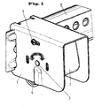
- FIG. 1 shows a perspective view of an embodiment of the present invention.
- the adjustable light barrier element comprises a transmitting or receiving element 2, which is rotatably mounted in the fastening housing 1.
- a control indicator is arranged at both ends. This indicator indicates whether the photocell is functioning properly.
- the transmitting or receiving element 2 can be rotated in the mounting housing until the indicator shows a proper functioning of the light barrier and the light barrier element is properly adjusted.
- the transmitting or receiving element can then be detected in the correct position by a locking element 4.
- the locking element 4 consists of a screw, which in a groove in the mounting housing runs and can be screwed into the transmitting or receiving element, so that the transmitting or receiving element in the correct adjustment position by tightening the screw 4 can be fixed.
- control indicator which z. B. may consist of a control lamp or an LED
- the indicator is very visible.
- a control indicator in the end of the axis of rotation is also on the other, not shown here side of the housing.
- the control display looks easily out of the mounting housing, so that each individual control display is visible from an angular range of 180 °.
- the control indicator is firmly connected to the transmitting or receiving element 2, so that it is not mechanically stressed by the rotation of the transmitting or receiving element 2.
- the mounting housing 1 is in turn attachable to a mounting bar 5 and slidable along this mounting bar 5, so that the position of the light barrier element along the mounting bar 5 can be changed.
- the mounting strip 5 also serves to guide the cable 6, which leads to the transmitting or receiving element 2.
- the mounting housing 1 consists of a metal sheet which has been bent in a U-shape and in whose opposite sides recesses for receiving the axis of rotation of the transmitting or receiving element are provided. At the open rear side, the fastening housing can be pushed onto the mounting strip 5 by overhanging elements, while the light beam emitted by the transmitting element or received by the receiving element can pass unhindered through the open front side of the fastening housing.
Landscapes
- Physics & Mathematics (AREA)
- Life Sciences & Earth Sciences (AREA)
- General Life Sciences & Earth Sciences (AREA)
- General Physics & Mathematics (AREA)
- Geophysics (AREA)
- Geophysics And Detection Of Objects (AREA)
- Illuminated Signs And Luminous Advertising (AREA)
Applications Claiming Priority (2)
| Application Number | Priority Date | Filing Date | Title |
|---|---|---|---|
| DE202006010344 | 2006-07-04 | ||
| DE202006011219U DE202006011219U1 (de) | 2006-07-04 | 2006-07-20 | Justierbares Lichtschrankenelement |
Publications (1)
| Publication Number | Publication Date |
|---|---|
| EP1876474A2 true EP1876474A2 (fr) | 2008-01-09 |
Family
ID=38626828
Family Applications (1)
| Application Number | Title | Priority Date | Filing Date |
|---|---|---|---|
| EP07011696A Withdrawn EP1876474A2 (fr) | 2006-07-04 | 2007-06-14 | Elément de barrière lumineuse ajustable |
Country Status (2)
| Country | Link |
|---|---|
| US (1) | US20080012719A1 (fr) |
| EP (1) | EP1876474A2 (fr) |
Families Citing this family (4)
| Publication number | Priority date | Publication date | Assignee | Title |
|---|---|---|---|---|
| USD616595S1 (en) * | 2009-04-21 | 2010-05-25 | Foxsemicon Integrated Technology, Inc. | Rotation adjusting device |
| USD616596S1 (en) * | 2009-04-21 | 2010-05-25 | Foxsemicon Integrated Technology, Inc. | Rotation adjusting device |
| USD616598S1 (en) * | 2009-04-21 | 2010-05-25 | Foxsemicon Integrated Technology, Inc. | Rotation adjusting device |
| USD616597S1 (en) * | 2009-04-21 | 2010-05-25 | Foxsemicon Integrated Technology, Inc. | Rotation adjusting device |
Family Cites Families (4)
| Publication number | Priority date | Publication date | Assignee | Title |
|---|---|---|---|---|
| US6662499B1 (en) * | 2002-05-31 | 2003-12-16 | Linear Corporation | Safety beam bracket and method of assembly |
| DE102004008059A1 (de) * | 2004-02-19 | 2005-09-22 | Sick Ag | Lichtschranke oder Lichtgitter mit Ausrichthilfe |
| DE102004021005A1 (de) * | 2004-04-20 | 2005-11-24 | Decoma (Germany) Gmbh | Haltevorrichtung für einen Sensor |
| WO2007034496A2 (fr) * | 2005-09-26 | 2007-03-29 | Shmuel Shaked | Barriere de reseau de faisceau lumineux devie |
-
2007
- 2007-06-14 EP EP07011696A patent/EP1876474A2/fr not_active Withdrawn
- 2007-07-03 US US11/824,989 patent/US20080012719A1/en not_active Abandoned
Also Published As
| Publication number | Publication date |
|---|---|
| US20080012719A1 (en) | 2008-01-17 |
Similar Documents
| Publication | Publication Date | Title |
|---|---|---|
| DE102005059538B4 (de) | Scharnier-Sensor | |
| EP0226532B1 (fr) | Cellule de commutation électrique avec une commande de déplacement pour un appareil de commutation mobile | |
| WO2016146218A1 (fr) | Charnière de porte ou de fenêtre | |
| DE102010044327A1 (de) | Zentrierspannvorrichtung | |
| AT508071B1 (de) | Möbelscharnier | |
| EP1876474A2 (fr) | Elément de barrière lumineuse ajustable | |
| AT501396B1 (de) | Falttürenscharnier | |
| EP0292743A1 (fr) | Ferme-porte avec dispositif indicateur de la force de fermeture | |
| EP1876320A1 (fr) | Emetteur de barrières lumineuses ajustable | |
| EP1722060B1 (fr) | Unité fonctionnelle d'un véhicule automobile | |
| DE202006003313U1 (de) | Lichtschrankengehäuse, Lichtschrankenelement und Torvorrichtungen | |
| EP2037027A1 (fr) | Guide-fil pour machine à tricoter rectiligne | |
| DE202006011219U1 (de) | Justierbares Lichtschrankenelement | |
| EP2470735B1 (fr) | Ensemble de poignées de porte | |
| DE102009004846B3 (de) | Scharnier für eine Tür | |
| DE8420711U1 (de) | Befestigungsvorrichtung für eine Dekorplatte an der Gerätetür eines Einbaukühlschrankes | |
| DE102011008419A1 (de) | Öffnungsfolgesteuerungseinrichtung einer zweiflügeligen Tür | |
| EP2161593A1 (fr) | Capteur optoélectronique et procédé d'application | |
| DE4111035A1 (de) | Scheinwerfer fuer kraftfahrzeuge | |
| DE19605541C2 (de) | Rückwandriegel für Möbel wie Schränke oder dergleichen | |
| DE19742143C1 (de) | Scharnierelement für ein Flügelteil | |
| EP0307696B1 (fr) | Compas pour un panneau oxillo-battant d'une fenêtre ou d'une porte | |
| DE2851658A1 (de) | Oberlichtoeffner o.dgl. | |
| DE2714550A1 (de) | Manometer in flachprofilbauweise | |
| DE2061790C3 (de) | Lüftungsvorrichtung für Fenster, Türen oder dgl |
Legal Events
| Date | Code | Title | Description |
|---|---|---|---|
| PUAI | Public reference made under article 153(3) epc to a published international application that has entered the european phase |
Free format text: ORIGINAL CODE: 0009012 |
|
| AK | Designated contracting states |
Kind code of ref document: A2 Designated state(s): AT BE BG CH CY CZ DE DK EE ES FI FR GB GR HU IE IS IT LI LT LU LV MC MT NL PL PT RO SE SI SK TR |
|
| AX | Request for extension of the european patent |
Extension state: AL BA HR MK YU |
|
| STAA | Information on the status of an ep patent application or granted ep patent |
Free format text: STATUS: THE APPLICATION IS DEEMED TO BE WITHDRAWN |
|
| 18D | Application deemed to be withdrawn |
Effective date: 20100105 |