EP1876432A1 - Module de pesée - Google Patents
Module de pesée Download PDFInfo
- Publication number
- EP1876432A1 EP1876432A1 EP06123692A EP06123692A EP1876432A1 EP 1876432 A1 EP1876432 A1 EP 1876432A1 EP 06123692 A EP06123692 A EP 06123692A EP 06123692 A EP06123692 A EP 06123692A EP 1876432 A1 EP1876432 A1 EP 1876432A1
- Authority
- EP
- European Patent Office
- Prior art keywords
- weighing module
- mounting device
- load
- weighing
- load cell
- Prior art date
- Legal status (The legal status is an assumption and is not a legal conclusion. Google has not performed a legal analysis and makes no representation as to the accuracy of the status listed.)
- Ceased
Links
Images



Classifications
-
- G—PHYSICS
- G01—MEASURING; TESTING
- G01G—WEIGHING
- G01G21/00—Details of weighing apparatus
- G01G21/23—Support or suspension of weighing platforms
-
- Y—GENERAL TAGGING OF NEW TECHNOLOGICAL DEVELOPMENTS; GENERAL TAGGING OF CROSS-SECTIONAL TECHNOLOGIES SPANNING OVER SEVERAL SECTIONS OF THE IPC; TECHNICAL SUBJECTS COVERED BY FORMER USPC CROSS-REFERENCE ART COLLECTIONS [XRACs] AND DIGESTS
- Y10—TECHNICAL SUBJECTS COVERED BY FORMER USPC
- Y10S—TECHNICAL SUBJECTS COVERED BY FORMER USPC CROSS-REFERENCE ART COLLECTIONS [XRACs] AND DIGESTS
- Y10S177/00—Weighing scales
- Y10S177/09—Scale bearings
Definitions
- the invention relates to a weighing module for a load cell to be arranged therein.
- Weigh modules can be used in different areas, depending on the type of load cell used and the desired load range.
- Weigh modules with high-load load cells are used primarily to determine the weight and to weigh the contents of large-volume containers, silos, tanks, reaction vessels and / or reaction containers. The weighing of the contents is generally carried out via a differential weighing between the empty and the filled container.
- Such weigh modules can also be used under extreme outdoor conditions, such as outdoors, in a technical facility or in a production plant.
- Centerlign has a self-centering, hermetically sealed highload load cell in the form of a rocker-pin load cell.
- Flexmount is a weighing module with a beam-shaped load cell and an overload protection.
- the load cell is usually arranged between two mounting devices, which are designed to mount the weigh module between a load and a load-bearing structure.
- Bar load cell is a load cell with an elongated shape, one end of which is generally fixedly connected to the weighing module and the other end is deflectable.
- a weighing module with a bar-shaped load cell for example, in the EP 1 275 943 A2 disclosed, wherein the load cell cooperates with a pin or spherical force transmission element.
- the known weighing modules are protected against mechanical damage to the weighing module and / or the load cell. They have, inter alia, Abhebommeen and / or overload protection, which is a tearing off a mounting device and / or destruction of the load cell, such as by to prevent the action of a heavy load. Furthermore, various means for aligning and / or limiting the play of the weighing module and in particular the mounting devices in relation to the weighing cell and each other are known.
- insulating mats are used for thermal insulation.
- These insulating mats can be arranged between the weighing module and the load to be determined or the supporting structure, for example between a mounting device and a fastening device connected thereto, for example a foot of a container to be weighed.
- the insulating mats are usually made of a material with low thermal conductivity, such as various plastics.
- a disadvantage of the use of such insulating mats is especially that they increase the height of the weighing module in addition due to their thickness and also wear over time, age and / or can move, so that the insulation effect uncontrollable can subside. If necessary, the insulating mats must be replaced even during operation, which can be very complex and costly especially in technical systems and weighing modules for high load applications.
- a weighing module for a load cell to be arranged therein has a first and a second mounting device.
- the first mounting device is in force contact with a load to be determined, for example a container to be weighed
- the second mounting device is connectable to a structure carrying the weighing module.
- the load-bearing structure may be, for example, the floor of a factory floor, the ground, a scaffolding or even a table, depending on the loads for which the weighing module is designed and which tasks it is to fulfill.
- the load cell is arranged between the two mounting devices, wherein it is suitable for the transport and / or the assembly to protect the load cell to exchange the load cell for a load cell dummy.
- At least one mounting device is configured such that it represents a means for thermal insulation, which thermally insulates the weighing module and in particular the load cell with respect to the load and / or the supporting structure.
- the means for thermal insulation may comprise different configurations of the mounting device.
- a first embodiment comprises the formation of at least one flat depression in the contact surface of the mounting device to the load or to the supporting structure.
- each depression represents a cavity, which is filled in the simplest case with air.
- the cavity is bounded on one side by the fixture itself and on the other by a fixture which forms part of the load or supporting structure. In this way, a stagnant air cushion is provided with very good insulator properties.
- the first and / or the second mounting device may have a single or several recesses, which are limited by material webs and / or supports.
- the voids formed after connecting the weighing module to the supporting structure and / or the load may be filled with either air or other substance, which is a good insulator, or a vacuum may be created in the cavity. The generation of a vacuum is only possible if the cavity can be closed gas-tight by a suitable cover.
- a further embodiment of the means for thermal insulation is the provision of at least one arranged in the load direction implementation in the first and / or the second mounting means.
- the implementation may for example be a simple bore, which serves the contact surface between a mounting device and the load and / or to reduce the load-bearing structure.
- a reduced contact surface requires an improvement of the insulation.
- the mounting device may be at least partially designed as a kind of cooling fin, whereby a temperature compensation between the weighing module and the room temperature is made possible due to passing air.
- the mounting device can represent a narrow or coarse-mesh grid, which also reduces the contact area between mounting device and load or load-bearing structure.
- a further embodiment comprises a mounting device with at least one feedthrough arranged vertically to the load direction.
- Feedthroughs arranged vertically to the load direction can be a type of pipe system which can be filled, for example, with an insulator and closed to the outside and / or open, so that, for example, air or another temperature control medium can be passed through.
- At least the first or the second mounting device has at least one means for thermal insulation, wherein both mounting devices can be configured with such means.
- the weighing module and in particular the load cell can in this way against thermal influences are protected, which are transferred from the load and / or the supporting structure to the weighing module
- the weighing module has at least one drain, which serves to discharge liquids and above all moisture from the weighing module.
- at least the mounting device connected to the supporting structure is designed as a drainage, in that its surface facing the weighing cell is designed to slope down towards the outer edges, so that moisture and liquids are discharged to the outside, ie away from the weighing module.
- a mounting device preferably the mounting device connected to the supporting structure, has an installation aid for the weighing cell.
- the installation aid is preferably channel-shaped, wherein the channel is configured sloping down to an outer edge of the mounting device, so that a load cell after connection of the mounting devices with the supporting structure and the load easily installed in the weighing module, removed from this and / or can be replaced ,
- a weighing module can accommodate different types of load cells with different load ranges.
- the usable load cells have an elastic deformation body provided with strain gauges and can be designed both as a "single-ended beam” load cell or as a rocker-pin load cell.
- the weighing cell cooperates with a force transmission element, which in a preferred embodiment is spherical.
- the force transmission element represents the force contact between the first mounting device and the load cell. This embodiment is particularly suitable when the weighing module is designed for a beam-shaped load cell.
- a weighing module for stabilizing a bar-shaped load cell can have lateral stops.
- the weighing cell and the force transmission element form a unit which has two convex cylinder end faces with the same or different geometry.
- An example of such a unit is a known rocker-pin load cell.
- Such a weighing module has no preferred installation direction, so that either one or the other mounting device can be connected to the load.
- the mobility of the weighing modules can be easily restricted and / or changed, in particular if several weighing modules are used to weigh a load so that the weighing modules are capable of exerting interfering forces without impairing the function and without tilting to absorb the load.
- modules with different degrees of mobility are combined in particular in weighing module arrangements.
- a backlash-free module is used as an anchor point or fixed point together with at least two movable and / or restrictedly movable modules.
- a weighing module arrangement is used with at least three weighing modules for determining the mass or a mass derivable physical mass of a load, such as a container and / or its contents, the load is firmly connected to the at least three weigh modules.
- FIG. 1 shows a simplified three-dimensional view of a weighing module according to the invention.
- the weighing module consists of two essentially plate-shaped mounting devices 1, 2 and a bar-shaped load cell 3 arranged between the mounting devices 1, 2.
- the weighing cell 3 can be any bar-shaped load cell or a load cell dummy. The use of a dummy is especially advantageous during transport and / or assembly of the weighing module.
- the weighing module is preferably oriented so that the first mounting device 1 is in force contact with a load to be determined and the second mounting device 2 is connected to a supporting structure.
- the mounting devices 1, 2 For attachment of the weighing module to the load and / or the supporting structure, the mounting devices 1, 2 at each corner on a passage 4 for a suitable fastening means.
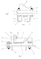
- a mounting device 1 in load contact with a load is shown in FIG. 3 and a mounting device 2 connected to a supporting structure is shown in FIG.
- the mounting device 1 On its side facing away from the load cell, the mounting device 1 has a single area depression 5, which extends almost over the entire surface of the mounting device 1.
- the recess 5 is bounded by a circumferential material web 6, the surface of which represents the contact surface to a fastening device for the load.
- the second mounting device 2 is connected in operation with a supporting structure and also has at each corner a passage 4 for a suitable fastening means.
- a base 8 On the load cell 3 side facing the mounting device 2, a base 8 is arranged, on which the load cell 3 is fixed.
- the load cell 3 is aligned such that one end is fixedly connected to the base 8.
- the other end is deflectable in the load direction and arranged at a certain distance from the mounting device 2, which is caused on the one hand by the height of the base 8 and on the other hand by the depth of an installation aid 9.
- the installation aid 9 is configured in the mounting device 2 as a channel-like depression and sloping from the base 8 to this opposite edge of the mounting device 2.
- the power transmission element (not shown here) establishes the force contact between the two mounting devices 1, 2.
- the weighing module on various security features.
- a multi-part lift-off element which here consists of interlocking hook-shaped means 10, 11.
- Two hooks 10 are connected to the first mounting device 1 and two further hooks 11 are connected to the second mounting device 2.
- the hooks 10, 11 engage each other in pairs and the load cell 3 is disposed between the two hook pairs 10, 11.
- the weighing module has an overload safety device 12 connected to the first mounting device 1, which can be seen better in FIGS. 2 and 3.
- the overload protection 12 and the hook pairs 10, 11 limit the horizontal play of the mounting devices 1, 2 to each other.
- the second mounting device 2 has three further passages 13, of which only one can be seen in this view. These bushings 13 can accommodate vertical limiting means, which with the hook 10 and the overload protection 12 arranged directly in relation to the drawing can interact. The arrangement and function of the vertical limiting means will be explained in more detail in connection with FIGS. 2 and 5.
- a known transverse link for compensating occurring torques and side loads can be attached to the weighing module.
- the second mounting device 2 has a mounting block 14 and the first mounting device 1 has at least one fastening device, which is designed here in the form of two holes 15.
- FIG. 2 shows a simplified side view A of the weighing module from FIG. In this view, it can be clearly seen that both the first mounting device 1, and the second mounting device 2 on their sides facing away from the load cell 3 each have a recess 5, 16, which for thermal insulation of the weighing module relative to the load and / or the supporting Serve structure.
- the hook 10 connected to the first mounting device 1 and also the overload protection 12 have at their free end in each case a recess 17 which can cooperate with vertical limiting means 18 which are arranged in the second mounting device 2.
- the dimension of the recess 17 is adapted to that of the vertical limiting means 18.
- a vertical limiting means 18 is arranged below the hook 10 and the overload protection 12 in the second mounting device.
- a vertical limiting means 18 consists of three functional parts, an anchoring 19, which is arranged essentially in the second mounting device 2, a head 20 with a cross section enlarged in comparison to the anchoring 19 and a stop 21 facing the first mounting device 1
- a screw with a head or a threaded rod with matching nut can be used.
- the limiting means 18 are designed to be adjustable, so that the height of the protruding from the second mounting means 2 part of the limiting means 18 and changed the vertical clearance of the two mounting devices can be adjusted to each other.
- the limiting means 18 not only serve as a stop for the overload protection 12 and the hooks 10, but can cooperate with these and define, for example, a basic position of the weighing module and / or even fix when the game between the two mounting devices 1, 2 by means of adjustable fastening means 18 is lifted.
- the power transmission element 22 may be either any known load receptor, but also, as shown here, be in two receiving cups 23, 24 movably mounted spherical element. A force contact between the two mounting devices 1, 2 is made only via the load cell 3 and in the receiving shells 23, 24 movable force transmission element 22.
- the receiving tray 23 is connected to the first mounting device 1 and the receiving tray 24 to the load cell 3.
- the receiving trays 23, 24 each have a concave trough 25, 26, which may have a circular or elliptical cross-section.
- the receiving tray 23 has a concave trough 25 with an elliptical cross-section, wherein the longitudinal axis of the trough 25 is perpendicular to the plane of the drawing.
- the receiving tray 23 can be locked in the bore 7 in the first mounting device.
- the bore 7 and also cooperating with this end of the receiving tray 23 is polygonal, in particular symmetrical, so for example square or designed as an equilateral hexagon, so that the receiving tray 23 can be arranged and fixed in several fixed predetermined positions, which in turn the deflection of the Power transmission element 22 can be pretended when the rotatable receiving tray has an elliptical trough 25.
- the other receiving tray 24 may be fixed and / or be connected in several angles lockable with the second mounting device 2 or the receiving tray 24th can be designed to reduce the total height of the weighing module on the load cell 3 and / or be integrated into this.
- the concave trough 26 in the receiving tray 24 is designed circular. Due to the different geometries of the receiving shells 23, 24, more precisely the elliptical trough 25 and the circular trough 26, the movement of the spherical force transmission element 22 is restricted and its deflection in a preferred direction, in particular along the longitudinal axis of the elliptical trough 25 steered.
- the hooks 10, 11 and the overload protection 12 fixed horizontal limiting means 31 and / or adjustable horizontal limiting means 32.
- the fixed limiting means 31 are here simple attacks, which are designed directly as part of the hook 10.
- An adjustable limiting means 32 may be, for example, a grub screw or a threaded rod which is guided in a passage 33 arranged perpendicular to the load direction.
- the hooks 10, 11 and the overload protection 12 can be configured with fixed 31 and / or with adjustable 32 horizontal limiting means, wherein adjustable limiting means 32 allow the adaptation of the weighing module to different external conditions.
- channel-shaped installation aid 9 and a drainage can be seen in Figure 2, which is configured in the load cell 3 facing surface 27 of the second mounting device 2.
- the surface 27 drops outwardly with respect to the drawing so that moisture and / or liquids impinging on the second mounting device 2 are rapidly dissipated.
- a comparable function also fulfills the installation aid 9.
- FIG 3 shows a simplified side view of a first mounting device 1 in an orientation which corresponds to the view from direction B of Figure 1.
- the overload protection 12 with a fixed horizontal limiting means 31 and a receiving tray 23 with a concave, elliptical trough 25 are arranged.
- the side facing away from the load cell during operation Mounting device 1 has a flat depression 5, which serves for thermal insulation of the weighing module.
- the recess 5 is bounded by a circumferential material web 6, the surface of which constitutes a contact surface for a fastening device 28.
- the fastening device 28 may be, for example, a flange whose dimensions are adapted to that of the mounting device 1.
- the fastening device 28 closes the recess 5 with respect to the drawing upwards to form a closed cavity.
- This cavity can for example be evacuated, that is, have a vacuum, or have a stagnant air cushion or be filled with a material of defined thermal conductivity, with a stationary air cushion is preferred.
- the fastening device 28 is connected by suitable fastening means 29 to the first mounting device 1, preferably four fastening means 29 are used, which are each arranged at a corner of the mounting device 1 (see also FIG. These means may comprise, as shown here, threaded screws and a nut, but also threaded rods with two nuts or other means known for fixing flanges.
- the fastening device 28 is in turn connected to a load 30, which is shown here as the foot of a container to be weighed.
- Figure 4 shows a simplified side view of a second mounting device 2 in the view from direction B (see Figure 1).
- the vertical limiting means see Figure 2 are not shown in this view.
- the second mounting device 2 has two hooks 11, of which only one can be seen here, a mounting block 14 for a control arm, a base 8 for attaching a beam-shaped load cell 3 and a sloping from the base 8 with respect to the drawing to the left, Channel-shaped installation aid 9.
- the load cell facing surface 27 of the second mounting device 2 is configured sloping to all sides.
- the load cell 3 is connected to a receiving tray 24 with a circular, concave trough 26, which can receive a spherical force transmission element 22.
- the second mounting device 2 is connected to a supporting structure 34, which preferably has a flange as fastening means 35.
- the mounting device 2 is connected by suitable fastening means 29 with the fastening device 35.
- the second mounting device like the first mounting device with or as shown here for the second mounting device 2, can be designed without means for thermal insulation.
- FIG. 5 shows a simplified plan view of a second mounting device 2 without a load cell, which additionally has lateral stops 36.
- the lateral stops 36 are arranged next to the base 8 for attachment of a bar-shaped load cell, not shown here, and again limit the lateral deflection of the load cell.
- the deflectable end of the load cell is disposed between the hooks 11, as indicated by the position of the power transmission element 22.
- a known transverse link can be attached directly to a lateral stop 36.
- the second mounting device 2 has a substantially rectangular shape, wherein at all four corners bushings 4 are provided for fastening means for fastening the second mounting device 2 to a supporting structure or a load.
- the second mounting device 2 on three bushings or holes 13.
- the holes 13 are arranged at the corners of a triangle whose center is determined approximately by the position of the force transmission element 22. The position of the holes 13 coincides approximately with the position of the hook and the overload protection in the established weighing module.
- Two bores 13 are arranged next to a hook 11 and between the hook 11 and a lateral stop 36, the third bore 13 is arranged in the channel 9 on the side opposite the base 8 side of the first mounting device 2.
- FIG. 6 shows a further embodiment of a weigh module according to the invention with a rocker-pin load cell 37 or a corresponding load cell dummy as a simplified side view.
- the load cell 37 is between two Mounting devices 38, 39 arranged.
- a rocker-pin load cell 37 has no preferred installation direction, so that in operation a mounting device 38, 39 is in force contact with the load to be determined and / or is connected to the supporting structure.
- Both mounting devices 38, 39 have on their side facing away from the load cell 37 a flat recess 40, 41 as a means for thermal insulation.
- a multi-part anti-lifting device 42 is arranged between the mounting devices 38, 39.
- the two mounting means 38, 39 are only in contact with each other via the weighing cell 37.
- the load cell 37 is mounted in two receiving shells 43, 44 which are each connected to one of the two mounting devices 38, 39.
- the receiving cups 43, 44 both have a concave trough 45, 46, which may have either a circular or an elliptical cross section.
- the trough 45 has an elliptical cross section and the trough 46 has a circular cross section.
- a preferred deflection direction of the rocker-pin load cell 39 can be determined.
- the dimensions of the weigh module can be adapted to the desired load cell 37, wherein load cells 37 can be used with different measurement ranges, ie high load load cells as well as precision load cells.
- the lift-off protection 42 consists of a multi-part lift-off element 47 connected to the mounting device 39 and a guide element 48 connected to the other mounting device 38, in which the multi-part lift-off element 47 is guided.
- the multi-part lift-off element 47 has a base 49 and a locking pin 50 detachably connected to this base 49. The connected to the base 49 end of the locking pin 50 has a smaller diameter than the free, directed against the mounting device 38 end.
- the multi-part lift-off element 47 is guided without contact in the guide element 48.
- the load for example, a container to be weighed, in contact with the mounting device 39 and the Mounting device 38 in contact with the supporting structure, wherein it is also possible to install the weighing module with opposite orientation.
- the two mounting devices 38, 39 are preferably plate-like and can be adapted to the shape of the container to be weighed and / or the supporting structure.
- both mounting devices 38, 39 have a plurality of suitable fastening means 29.
- the locking pin 50 is arranged without contact in a recess 51 in the guide element 48 and serves to prevent falling apart of the weighing module.
- the recess 51 in the guide element 48 is designed so that the multi-part lift-off element 47 is guided therein without contact and is arranged at a certain distance from the mounting device 38 when the weighing module is optimally aligned.
- the guide element 48 thus represents a type of sleeve for receiving the multi-part Abhebelements 47, wherein the shape of the recess 51 substantially corresponds to the shape of the multi-part Abhebelements 47.
- the guide member 48 thus acts both as a horizontal and as a vertical limiting means and the locking pin 50 is a kind of overload protection.
- a plurality of limiting means 52 can be arranged in the guide member 48, which the distance between the Limit lifting elements 47 and the guide member 48.
- such limiting means 52 and thus the game are adjustable.
- FIGS. 7 to 11 show various possible embodiments of a means for thermal insulation.
- FIGS. 7, 10 and 11 are schematic plan views of one and in FIGS. 7 to 9 are side views of a mounting device with a means for thermal insulation.
- FIG. 7 shows a mounting device 59 in a plan view and a side view with a flat depression 5, as has already been shown in FIG.
- the recess 5 on the mounting device 59 is limited by material webs 6 and the mounting device 59 has at the corners of the bushings 4 for fastening means.
- Figure 8 shows a side view of a mounting unit 59 with a recess 5 on the side facing away from the load cell in operation and a plurality of recesses 53 on the opposite side.
- the recesses 53 are arranged so that they form a kind of cooling rib 54, whereby an additional heat dissipation by passing air is made possible.
- Figure 9 shows two side views of a mounting device, which instead of a recess in the surface facing away from the load cell, one or as shown here a plurality of passages 55, 56, 57 which are formed perpendicular to the load direction in the mounting device.
- the feedthroughs may be either open or closed to the environment and optionally filled with a material having a given thermal conductivity.
- the bushings 55 have only one opening to the environment.
- the passages 55 are dimensioned so that several can be arranged in a plane next to each other. Comparable are the bushings 56 which are smaller than the passages 55 and extend through the mounting device.
- the passage 57 is formed as a cavity which extends almost through the entire mounting device.
- the feedthroughs can also be designed in the load direction, so that the means for thermal insulation is designed as a kind of grid on the mounting device.
- FIG. 10 shows a plan view of a mounting device 59 with a plurality of depressions 5 separated from one another by material webs 6. Approximately in the center of the mounting device, the lead-through 7 for attachment of a receiving tray can be seen in this view (see also FIG. 1).
- FIG. 11 likewise shows a plan view of a mounting device 59 with a flat depression 5 and a multiplicity of supports 58.
- This embodiment is particularly advantageous in applications in the heavy-duty sector, since both high structural stability and thermal insulation of the weighing module can be ensured.
- thermal insulation means shown in FIGS. 7 to 11 can in principle be used in all weighing modules which have a weighing cell and one or two mounting devices.
- the means shown can be combined as desired in a weighing module and configured both in a mounting device in contact with a load and in a mounting device connected to a supporting structure.
- a weighing module arrangement for weighing a large-volume container usually comprises at least three weighing modules, one of which is set virtually free of play and the others have a predetermined game.
- the weighing modules are aligned depending on the shape of the container, in particular the shape of its base, to each other.
- the orientation of the individual weighing modules relative to one another is selected such that neither interfering disturbing forces nor thermal expansion or contraction of the container influence the weighing result.
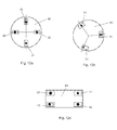
- FIGS. 12a to 12c illustrate examples of different weighing module arrangements.
- FIG. 12 a shows a container 60 with a round base and a weighing module arrangement fixedly connected to the container 60.
- the weighing module arrangement comprises four radially oriented weighing modules 61, 62, 63, which are arranged at the edge of the container 60 offset by 90 ° to each other.
- the longitudinal axes of the substantially rectangular weighing modules 61, 62, 63 are aligned radially with respect to the base of the container 60.
- a weighing module 61 is set almost free of play and serves as a fixed point.
- a weighing module 63 which is movable in a limited manner in one direction. The last two positions are occupied by two fully mobile weighing modules 62.
- the setting of the weighing modules 61, 62 and 63 are determined by alignment and / or configuration of the receiving trays by either one of the receiving trays is determined in a new position, as by means of in FIGS 1 and 2 is provided, or by simply replacing one of the two receiving cups against another receiving tray.
- a bar-type load cell replacement of the associated with a mounting device receiving tray is preferred.
- a backlash-free weighing module 61 is realized by using two receiving trays with elliptical troughs which are arranged so that their longitudinal axes are orthogonal to one another.
- a limited movable weighing module 63 preferably has a receiving tray with a circular trough and a receiving tray with an elliptical trough, wherein by rotation of the elliptical receiving tray, the preferred direction of movement can be changed as desired.
- a freely movable weighing module 62 comprises two receiving trays with circular troughs.
- FIG. 12b likewise shows a container 60 with a round base.
- the weighing module arrangement fixedly connected to the container 60 comprises three weighing modules 61, 62, 70, which are aligned tangentially at the edge of the container 60.
- the arrangement is formed by a backlash-free weighing module 61, a limited movable weighing module 70 and a fully movable weighing module 63, which are arranged with respect to the base of the container 60 at a distance of approximately 120 ° to each other.
- FIG. 12c shows a container 64 with an angular base. It is supported by four weigh modules 61, 62, 63, which are arranged at the four corners of the container 64. Two freely movable weighing modules 62 are arranged at diagonally opposite corners and at the other two corners a play-free weighing module 61 and a limited movable weighing module 62 are arranged.
- the weighing modules have a supporting function and establish the contact between the container and the structure carrying the container.
- a misadjustment of the weighing module thus has an impact on the stability of the container, which must be constantly ensured especially in aggressive and / or environmentally harmful content. For this reason, it is necessary to design the weighing modules as stable as possible and to protect them against acting, overloads, disturbing forces and / or torques.
- the steering and limiting the movement of the power transmission element and thus the game of the individual weighing module is particularly advantageous if the extension of the container to be weighed or the load to be weighed changes, as may happen, for example due to temperature changes.
Landscapes
- Physics & Mathematics (AREA)
- General Physics & Mathematics (AREA)
- Measurement Of Force In General (AREA)
- Battery Mounting, Suspending (AREA)
- Secondary Cells (AREA)
Applications Claiming Priority (1)
| Application Number | Priority Date | Filing Date | Title |
|---|---|---|---|
| US11/482,155 US7371978B2 (en) | 2006-07-07 | 2006-07-07 | Thermally insulated weighing module |
Publications (2)
| Publication Number | Publication Date |
|---|---|
| EP1876432A1 true EP1876432A1 (fr) | 2008-01-09 |
| EP1876432A8 EP1876432A8 (fr) | 2008-03-26 |
Family
ID=37487428
Family Applications (1)
| Application Number | Title | Priority Date | Filing Date |
|---|---|---|---|
| EP06123692A Ceased EP1876432A1 (fr) | 2006-07-07 | 2006-11-08 | Module de pesée |
Country Status (4)
| Country | Link |
|---|---|
| US (1) | US7371978B2 (fr) |
| EP (1) | EP1876432A1 (fr) |
| JP (1) | JP2008046115A (fr) |
| CN (1) | CN101101231B (fr) |
Cited By (2)
| Publication number | Priority date | Publication date | Assignee | Title |
|---|---|---|---|---|
| EP1876433A3 (fr) * | 2006-07-07 | 2008-03-26 | Mettler-Toledo AG | Module de pesage |
| EP2434265A1 (fr) | 2010-09-22 | 2012-03-28 | Wipotec Wiege- und Positioniersysteme GmbH | Dispositif de pesage avec découplage thermique |
Families Citing this family (23)
| Publication number | Priority date | Publication date | Assignee | Title |
|---|---|---|---|---|
| CN101680798B (zh) * | 2007-06-01 | 2012-05-09 | 梅特勒-托利多公开股份有限公司 | 特别地用于重量测量仪器的可调节平行引导机构 |
| BRPI1000208A2 (pt) * | 2010-01-29 | 2011-01-04 | Sppt Pesquisas Tecnologicas Ltda | equipamento trocador de calor vibrante para conversão de baixa temperatura para tratamento de resìduos orgánicos e processo de tratamento de resìduos orgánicos mediante emprego de equipamento trocador de calor vibrante para conversão de baixa temperatura |
| ES2640129T3 (es) * | 2010-03-11 | 2017-10-31 | Leifheit Ag | Báscula con células de pesaje planas |
| CN101949730B (zh) * | 2010-08-25 | 2012-05-16 | 梅特勒-托利多(常州)测量技术有限公司 | 称重模块 |
| US8778773B2 (en) | 2010-12-16 | 2014-07-15 | Soitec | Methods for directly bonding together semiconductor structures, and bonded semiconductor structures formed using such methods |
| US8923003B2 (en) | 2012-02-06 | 2014-12-30 | Apple Inc. | Flexible circuit connectors with reduced profiles |
| CN103674212B (zh) * | 2012-09-19 | 2017-11-28 | 梅特勒-托利多有限公司 | 测力计称重模块 |
| US9709436B2 (en) | 2013-03-15 | 2017-07-18 | Illinois Tool Works Inc. | Load cell that is symmetrical about a central vertical axis |
| DE102014101561A1 (de) * | 2013-11-08 | 2015-05-13 | Sartorius Lab Instruments Gmbh & Co. Kg | Dosiervorrichtung mit integrierter Waage und Klimamodul |
| US10126161B2 (en) * | 2015-03-26 | 2018-11-13 | A&D Company, Limited | Overload prevention mechanism |
| DE102015104693B4 (de) * | 2015-03-27 | 2017-06-29 | Sartorius Lab Instruments Gmbh & Co. Kg | Waage mit Lastwechseleinrichtung und Verfahren zu deren Betrieb |
| CN205091041U (zh) * | 2015-05-15 | 2016-03-16 | 永正传感(杭州)有限公司 | 支脚称重传感器 |
| CN106338328B (zh) * | 2015-07-15 | 2022-04-12 | 梅特勒-托利多仪器(上海)有限公司 | 称重传感器组件以及电子天平 |
| EP3153830B1 (fr) * | 2015-10-06 | 2018-06-20 | Mettler-Toledo GmbH | Support de charge ayant un dispositif de verrouillage |
| CN105698913A (zh) * | 2016-01-27 | 2016-06-22 | 苏州翠南电子科技有限公司 | 一种桥式称重传感器 |
| US10775227B2 (en) | 2016-02-03 | 2020-09-15 | Mettler-Toledo Precision Instrument Company Limited | Weigh module with supporting member |
| EP3411676A4 (fr) | 2016-02-03 | 2019-09-18 | Mettler Toledo (Changzhou) Precision Instrument Ltd. | Module de pesée |
| US10768043B2 (en) | 2016-02-03 | 2020-09-08 | Mettler-Toledo Precision Instrument Company Limited | Weigh module with guiding arrangement |
| CN107036697A (zh) * | 2016-02-03 | 2017-08-11 | 梅特勒-托利多(常州)精密仪器有限公司 | 称重模块 |
| CN105865603A (zh) * | 2016-04-21 | 2016-08-17 | 邹平县供电公司 | 一种称量超长货物的小型电子秤称重托架 |
| IT201700097529A1 (it) * | 2017-08-30 | 2019-03-02 | Pavone Sistemi S R L | Modulo di pesatura perfezionato a cella di carico |
| CN107870030A (zh) * | 2017-10-20 | 2018-04-03 | 六六房车有限公司 | 一种具有手控翻转易收纳调节机构的称重模块 |
| DE102019112871B4 (de) * | 2019-05-16 | 2021-06-17 | Flintec Gmbh | Wägemodul und Wägeeinrichtung |
Citations (2)
| Publication number | Priority date | Publication date | Assignee | Title |
|---|---|---|---|---|
| DE3743356A1 (de) | 1987-12-21 | 1989-06-29 | Sartorius Gmbh | Oberschalige elektronische waage |
| EP1275943A2 (fr) * | 2001-07-11 | 2003-01-15 | PM On Board Ltd. | Dispositif mobile pour peser une charge |
Family Cites Families (25)
| Publication number | Priority date | Publication date | Assignee | Title |
|---|---|---|---|---|
| US2714536A (en) * | 1950-03-06 | 1955-08-02 | Wirth Armin | Scale bearings |
| US3915248A (en) * | 1975-01-10 | 1975-10-28 | Owen Paelian | Weighing system |
| US4258810A (en) * | 1979-05-25 | 1981-03-31 | Masstron Scale, Inc. | Weighing apparatus |
| US4411327A (en) * | 1981-05-14 | 1983-10-25 | Hottinger Baldwin Measurements, Inc. | Apparatus for applying a load to a strain gage transducer beam |
| US4554987A (en) * | 1983-08-29 | 1985-11-26 | Dillon Benny N | Self-aligning scale assembly and method |
| US4483404A (en) * | 1983-08-30 | 1984-11-20 | Benny N. Dillon | Self-aligning scale assembly |
| CA1249611A (fr) * | 1984-10-05 | 1989-01-31 | Franz Balduin | Dispositif de pesage |
| DE3544885A1 (de) * | 1985-12-18 | 1987-06-19 | Pfister Gmbh | Kraftmesseinrichtung |
| US4880069A (en) * | 1988-08-30 | 1989-11-14 | Weigh-Tronix, Inc. | Electronic bathroom scale |
| US4991692A (en) * | 1989-03-24 | 1991-02-12 | Spectra-Physics | Spill control mounting for data gathering system |
| JPH0738933U (ja) * | 1993-12-24 | 1995-07-14 | 大和製衡株式会社 | 荷重検出装置 |
| JPH08136363A (ja) * | 1994-09-14 | 1996-05-31 | Ishida Co Ltd | ロードセルとこれを用いた計量装置 |
| US5929390A (en) * | 1994-09-14 | 1999-07-27 | Ishida Co., Ltd. | Load cell weighing apparatus using the same |
| JPH0943270A (ja) * | 1995-07-26 | 1997-02-14 | Ngk Spark Plug Co Ltd | 圧電型力学量センサ |
| JPH10221183A (ja) * | 1996-12-05 | 1998-08-21 | Satake Eng Co Ltd | ロードセル荷重検出器の温度補償方法及びその装置 |
| GB9808768D0 (en) * | 1998-04-25 | 1998-06-24 | Nova Weigh Limited | Improved weighing assembly |
| US6924441B1 (en) * | 1999-09-29 | 2005-08-02 | Hill-Rom Services, Inc. | Load cell apparatus |
| US6433289B1 (en) * | 1999-10-25 | 2002-08-13 | Scaleco | Weighing device |
| JP3506661B2 (ja) * | 2000-08-15 | 2004-03-15 | 八洲器材株式会社 | 鉄道車両の輪重測定装置 |
| ATE301827T1 (de) * | 2002-03-18 | 2005-08-15 | Mettler Toledo Gmbh | Kraftaufnehemer, kraftaufnehmer mit einer montagevorrichtung und waage. |
| JP2004043532A (ja) * | 2002-07-09 | 2004-02-12 | Tetsuo Masui | 廃プラスチックの油化装置 |
| JP2004085332A (ja) * | 2002-08-27 | 2004-03-18 | Sartorius Kk | 構造物の計量用支持構造体 |
| CN2650085Y (zh) * | 2003-07-09 | 2004-10-20 | 英展实业股份有限公司 | 可自动调整内压力的电子秤 |
| JP4625676B2 (ja) * | 2004-10-21 | 2011-02-02 | 株式会社エー・アンド・デイ | 荷重変換器 |
| US7202425B2 (en) * | 2005-04-13 | 2007-04-10 | The Montalvo Corporation | Under-pillow-block load cell |
-
2006
- 2006-07-07 US US11/482,155 patent/US7371978B2/en not_active Expired - Fee Related
- 2006-11-08 EP EP06123692A patent/EP1876432A1/fr not_active Ceased
-
2007
- 2007-07-06 CN CN200710128314XA patent/CN101101231B/zh not_active Expired - Fee Related
- 2007-07-09 JP JP2007179224A patent/JP2008046115A/ja active Pending
Patent Citations (2)
| Publication number | Priority date | Publication date | Assignee | Title |
|---|---|---|---|---|
| DE3743356A1 (de) | 1987-12-21 | 1989-06-29 | Sartorius Gmbh | Oberschalige elektronische waage |
| EP1275943A2 (fr) * | 2001-07-11 | 2003-01-15 | PM On Board Ltd. | Dispositif mobile pour peser une charge |
Cited By (2)
| Publication number | Priority date | Publication date | Assignee | Title |
|---|---|---|---|---|
| EP1876433A3 (fr) * | 2006-07-07 | 2008-03-26 | Mettler-Toledo AG | Module de pesage |
| EP2434265A1 (fr) | 2010-09-22 | 2012-03-28 | Wipotec Wiege- und Positioniersysteme GmbH | Dispositif de pesage avec découplage thermique |
Also Published As
| Publication number | Publication date |
|---|---|
| US7371978B2 (en) | 2008-05-13 |
| JP2008046115A (ja) | 2008-02-28 |
| US20080006451A1 (en) | 2008-01-10 |
| CN101101231B (zh) | 2011-12-14 |
| CN101101231A (zh) | 2008-01-09 |
| EP1876432A8 (fr) | 2008-03-26 |
Similar Documents
| Publication | Publication Date | Title |
|---|---|---|
| EP1876433A2 (fr) | Module de pesage | |
| EP1357367B1 (fr) | Balance avec élément de support pour connecter un plateau avec un capteur de pesage | |
| DE2546890C3 (de) | Montage- und Schutzorgan bei Kraftmessungs- oder Wiegevorrichtungen | |
| EP2032954A1 (fr) | Système d'étalonnage pour une balance électronique | |
| EP1564534B1 (fr) | Module à cellule de charge | |
| EP3670067B1 (fr) | Dispositif de positionnement de type à portique | |
| EP4080176B1 (fr) | Balance dotée d'une plateforme de mesure portée par des pieds supports | |
| EP2507564A2 (fr) | Ensemble support pour une installation solaire | |
| EP1672335B1 (fr) | Module de pesée muni d'un dispositif anti-surchage | |
| EP0104557A2 (fr) | Balance | |
| DE69008136T2 (de) | Bauliche Anordnung für ein Fundament eines Antennenmastes mit Hochleistungssender. | |
| DE2121357B2 (de) | Lastmessvorrichtung | |
| EP0982823B1 (fr) | Installation de commutation avec des moyens de fixation | |
| DE3236371C2 (de) | Thermostatventil | |
| EP3698067B1 (fr) | Amortisseur de vibration, en particulier pour une armoire de distribution | |
| EP3845872B1 (fr) | Cellule de pesage | |
| EP3334476A1 (fr) | Appareil de dialyse péritonéale | |
| EP1530035B1 (fr) | Cellule de mesure de force avec découplage de fixation par surfaces surélevées et courtes incisions | |
| EP4274093B1 (fr) | Système de montage pour modules photovoltaïques et composants de système de montage pour modules photovoltaïques améliorant l'installation | |
| EP1706713B1 (fr) | Capteur de pesee | |
| WO2017162565A1 (fr) | Dispositif pivotant de retenue, de support et/ou de déplacement pour modules solaires | |
| DE10229016B4 (de) | Schwenklager | |
| EP1406021B1 (fr) | Dispositif à fixation | |
| DE2152504C3 (de) | Einbaugehäuse für eine elektromechanische Wägezelle | |
| DE102005048727B3 (de) | Lagerstütze für Extruderzylinder und Extruder |
Legal Events
| Date | Code | Title | Description |
|---|---|---|---|
| PUAI | Public reference made under article 153(3) epc to a published international application that has entered the european phase |
Free format text: ORIGINAL CODE: 0009012 |
|
| AK | Designated contracting states |
Kind code of ref document: A1 Designated state(s): AT BE BG CH CY CZ DE DK EE ES FI FR GB GR HU IE IS IT LI LT LU LV MC NL PL PT RO SE SI SK TR |
|
| AX | Request for extension of the european patent |
Extension state: AL BA HR MK YU |
|
| RAP1 | Party data changed (applicant data changed or rights of an application transferred) |
Owner name: METTLER-TOLEDO AG |
|
| 17P | Request for examination filed |
Effective date: 20080708 |
|
| 17Q | First examination report despatched |
Effective date: 20080814 |
|
| AKX | Designation fees paid |
Designated state(s): AT BE BG CH CY CZ DE DK EE ES FI FR GB GR HU IE IS IT LI LT LU LV MC NL PL PT RO SE SI SK TR |
|
| STAA | Information on the status of an ep patent application or granted ep patent |
Free format text: STATUS: THE APPLICATION HAS BEEN REFUSED |
|
| 18R | Application refused |
Effective date: 20130517 |