EP1876471A1 - Dispositif et procédé d'imagerie - Google Patents
Dispositif et procédé d'imagerie Download PDFInfo
- Publication number
- EP1876471A1 EP1876471A1 EP06013850A EP06013850A EP1876471A1 EP 1876471 A1 EP1876471 A1 EP 1876471A1 EP 06013850 A EP06013850 A EP 06013850A EP 06013850 A EP06013850 A EP 06013850A EP 1876471 A1 EP1876471 A1 EP 1876471A1
- Authority
- EP
- European Patent Office
- Prior art keywords
- radiation
- shutter
- imaging apparatus
- radiation detector
- source
- Prior art date
- Legal status (The legal status is an assumption and is not a legal conclusion. Google has not performed a legal analysis and makes no representation as to the accuracy of the status listed.)
- Withdrawn
Links
- 238000003384 imaging method Methods 0.000 title claims abstract description 47
- 230000005855 radiation Effects 0.000 claims abstract description 186
- 238000003325 tomography Methods 0.000 claims abstract description 28
- 230000000873 masking effect Effects 0.000 claims abstract description 19
- 230000005540 biological transmission Effects 0.000 claims abstract description 10
- 238000004458 analytical method Methods 0.000 claims abstract description 9
- 230000033001 locomotion Effects 0.000 claims description 16
- 229910052704 radon Inorganic materials 0.000 claims description 12
- SYUHGPGVQRZVTB-UHFFFAOYSA-N radon atom Chemical compound [Rn] SYUHGPGVQRZVTB-UHFFFAOYSA-N 0.000 claims description 12
- 230000000903 blocking effect Effects 0.000 claims description 6
- 238000011156 evaluation Methods 0.000 claims description 6
- 230000005670 electromagnetic radiation Effects 0.000 claims 1
- 238000000034 method Methods 0.000 claims 1
- 230000003287 optical effect Effects 0.000 description 17
- 238000012545 processing Methods 0.000 description 4
- 230000001419 dependent effect Effects 0.000 description 2
- 230000002238 attenuated effect Effects 0.000 description 1
- 238000002591 computed tomography Methods 0.000 description 1
- 238000010586 diagram Methods 0.000 description 1
- 238000005259 measurement Methods 0.000 description 1
- 238000012986 modification Methods 0.000 description 1
- 230000004048 modification Effects 0.000 description 1
- 238000011160 research Methods 0.000 description 1
- 238000005070 sampling Methods 0.000 description 1
Images


Classifications
-
- G—PHYSICS
- G01—MEASURING; TESTING
- G01T—MEASUREMENT OF NUCLEAR OR X-RADIATION
- G01T1/00—Measuring X-radiation, gamma radiation, corpuscular radiation, or cosmic radiation
- G01T1/29—Measurement performed on radiation beams, e.g. position or section of the beam; Measurement of spatial distribution of radiation
- G01T1/2914—Measurement of spatial distribution of radiation
- G01T1/2985—In depth localisation, e.g. using positron emitters; Tomographic imaging (longitudinal and transverse section imaging; apparatus for radiation diagnosis sequentially in different planes, steroscopic radiation diagnosis)
Definitions
- the invention relates to an imaging apparatus, particularly to a tomography apparatus, and to a corresponding imaging method according to the independent claims.
- Tomography apparatuses are well known and widely used in the fields of medical science and materials research as a diagnostic tool for generating sectional views of an object, e.g. the human body.
- the conventional tomography apparatuses comprise a radiation source, e.g. an X-ray source, rotating relative to the object and transmitting radiation through the object at different angles.
- a radiation detector is disposed on the other side of the object for detecting the radiation after transmission through the object.
- the radiation detector comprises a large number of picture elements in order to achieve a high optical resolution. In this way, so-called Radon data are generated, which are representing properties (e.g.
- One problem of the aforementioned conventional tomography apparatuses is that the optical resolution is restricted by the number and size of the picture elements of the radiation detector. On the one hand, a large number and a small size of the picture elements are desirable in order to obtain a high optical resolution of the tomography apparatus. On the other hand, radiation detectors having a large number of picture elements are quite expensive and require a high dose for a sufficient signal to noise ratio (SNR).
- SNR signal to noise ratio
- the invention provides an imaging apparatus, particularly a tomography apparatus, for analysing an object comprising a radiation source for transmission of radiation through the object in a section plane of the object and further comprising a radiation detector for detecting the radiation in the section plane of the object after transmission through the object.
- the imaging apparatus comprises a masking device for masking out a part of the radiation, wherein the masked part of the radiation is movable in the section plane relatively to the radiation detector during the analysis of the object.
- the Radon data are calculated from the differences of the detector output during the movement of the masked part of the radiation.
- the invention achieves a high optical resolution by moving the masked part of the radiation relatively to the detector, so that the data generated by the radiation detector are representative of a specific angle as in the conventional radiation detectors having a large number of picture elements.
- the optical resolution of the imaging apparatus is determined by the motion speed of the masked part of the radiation and the sampling rate of the measurements of the radiation detector.
- the masking device comprises a movable shutter being disposed in the path of the radiation between the radiation source and the radiation detector, so that the shutter is blocking, i.e. shielding, a part of the radiation depending on its position.
- the shutter is an opto-mechanical component, which is intransparent with regard to the radiation and which can be moved relatively to the detector.
- the shutter is disposed between the radiation source and the object.
- the shutter can be linearly or rotary movable.
- the shutter is preferably cylindrical and surrounding the object or the radiation source, wherein the object is preferably disposed on the axis of rotation of the shutter.
- the shutter is preferably a single-edge shutter blocking the radiation in the section plane on one side only.
- the slot shutter is blocking the radiation on both sides of the slot.
- the imaging apparatus of the invention preferably comprises a drive for moving the shutter with a defined motion speed and a feedback controller for closed loop controlling of the motion speed of the shutter depending on the output of the radiation detector. If the output of the radiation detector indicates a detail within the object, the feedback controller preferably reduces the motion speed of the shutter, so that the optical resolution is increased at the position of the detail within the object. However, if the output of the radiation detector indicates a homogeneous part of the object, the feedback controller preferably increases the motion speed of the shutter, since a high optical resolution is not necessary in homogeneous parts of the object.
- the masking device does not comprise an opto-mechanical shutter. Instead, the masking device is making the radiation detector partially insensitive in order to mask out a corresponding part of the radiation.
- the masking device and the radiation detector can be integrated in a single component thereby reducing the complexity and the costs of the imaging apparatus according to the invention.
- a multi-channel radiation detector might be used having several picture elements, which are selectively deactivated in order to mask out a part of the radiation in the region of the deactivated picture elements.
- the masked part of the radiation i.e. the blocked or shielded part of the radiation
- the radiation detector is fixedly arranged, whereas the masked part of the radiation is movable, e.g. by moving the aforementioned opto-mechanical shutter.
- the masked part of the radiation is fixedly arranged, e.g. due to a stationary shutter, whereas the radiation detector is movable, e.g. by rotating the radiation detector around the object.
- both the radiation detector and the masked part of the radiation are being moved during the analysis of the object, e.g. by moving both the radiation detector and the shutter.
- the radiation detector preferably comprises a single output channel, so that an inexpensive radiation detector can be used.
- a radiation detector having multiple (e.g. five) output channels wherein the masking device is used to increase the optical resolution.
- the imaging apparatus of the invention preferably comprises a rotary carrier receiving the object, wherein the rotary carrier has an axis of rotation, which is aligned perpendicular to the section plane through the object.
- the imaging apparatus preferably comprises a drive for rotating the carrier along with the object around the axis of rotation, whereas the radiation detector is preferably fixed. The object is preferably rotated in order to generate the aforementioned so-called Radon data.
- the radiation source is not necessarily an X-ray source as initially mentioned.
- the radiation source can be an ultrasonic source, a light source, particularly a laser, a Gamma radiation source, a neutron source, an electron source, a radiation source emitting electro-magnetic waves, particularly microwaves, or a radiation source emitting ionising or non-ionising radiation.
- the imaging apparatus according to the invention is not restricted to a specific type of radiation.
- the imaging apparatus preferably comprises an evaluation unit connected to the radiation detector for generating Radon data from the detected radiation, wherein the Radon data are representing properties of the object, so that a sectional view of the object can be generated by processing the Radon data.
- the evaluation unit is not necessarily part of the invention, so that the imaging apparatus of the invention can be realized as a separate system delivering imaging data to the evaluation unit, which is a separate system.
- the invention is not restricted to the aforementioned imaging apparatus but also relates to a corresponding imaging method.
- the invention is not restricted to the use as a diagnostic tool in the field of medical science. Further, the imaging apparatus of the invention can also be used for analysing mechanical components of a machine, particularly of a spacecraft or an aircraft.
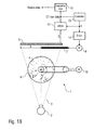
- FIGS 1A and 1B schematically show a preferred embodiment of a tomography apparatus 1 according to the invention.
- the tomography apparatus 1 comprises a radiation source 2 emitting radiation 3 in a section plane in the direction of an object 4, e.g. a human body, wherein the section plane is identical with the plane of the drawing.
- the invention is not restricted to the analysis of the human body. Instead, other types of objects can be analysed, e.g. mechanical parts of machines, particularly of aircrafts or spacecrafts.
- the radiation source 2 is an X-ray source.
- other types of radiation sources can be used within the framework of the invention.
- the tomography apparatus 1 comprises a radiation detector 5, which is disposed in the path of the radiation 3 behind the object 4, so that the radiation detector 5 detects the radiation 3 after transmission through the object 4.
- the radiation detector 5 comprises a single output channel 6 only, so that the radiation detector 5 is quite inexpensive compared with multi-channel radiation detectors as used in conventional tomography apparatuses.
- the tomography apparatus 1 comprises an opto-mechanical shutter 7, which is disposed in the path of the radiation 3 between the object 4 and the radiation detector 5.
- the shutter 7 is linearly movable by a motor 8, so that the shutter 7 is masking out a part of the radiation 3 depending on the position s of the shutter 7 relative to the radiation detector 5.
- the object 4 is disposed on a rotary carrier 9, which is rotatable around an axis of rotation, which is aligned perpendicular to the section plane of the object 4, i.e. the plane of the drawing.
- the tomography apparatus 1 comprises a motor 10, which is rotating the rotary carrier 9 along with the object 4 during the analysis of the object.
- the radiation detector 5 detects an intensity D of a part the radiation 3, which is transmitted through the object 4 and not blocked by the opto-mechanical shutter 7. Therefore, the intensity D of the detected radiation 3 depends both on the position s of the shutter 7 and the properties of the object 4, i.e. the attenuation of the radiation 3 by the object 4.
- the intensity D is approximately linearly dependent on the position s of the opto-mechanical shutter 7 as shown by the dashed line in Fig. 2.
- the intensity D is not only dependent on the position s of the opto-mechanical shutter 7, but also depends on optical properties of the object 4. Therefore, the inclination of the curve as shown in Fig. 2 depends on local variations of the optical properties of the object 4.
- the single output channel 6 of the radiation detector 5 is connected to a differentiator 11, which calculates the derivative dD/ds of the intensity D with regard to the position s of the shutter 7, since this derivative is indicative of the optical properties of the object 4.
- the differentiator 11 is connected to an evaluation unit 12, which generates conventional Radon data for further processing as known in the state of the art.
- the differentiator 11 is connected to a controller 13, which actuates a driver 14.
- the driver 14 in turn actuates the motor 8, which moves the shutter 7. Therefore, the controller 13 controls the motion speed ds/dt of the opto-mechanical shutter 7 depending on the derivative dD/ds, so that the motion speed of the shutter 7 is closed loop controlled by the controller 13.
- the feedback controller 13 preferably reduces the motion speed ds/dt of the shutter 7, so that the optical resolution is increased at the position of the detail within the object 4.
- the feedback controller 13 preferably increases the motion speed ds/dt of the shutter 7, since a high optical resolution is not necessary in homogeneous parts of the object 4.
- the afore-mentioned tomography apparatus 1 allows several modes of operation, which will be explained in the following.
- the shutter 7 is moved discontinously, i.e. step-by-step, and the radiation detector 5 is resetted after each step.
- the shutter 7 is moved continously and the radiation detector is resetted periodically.
- the radiation detector 5 is not resetted during the analysis of the object 4. Further, the shutter 7 can be moved either discontinuously, i.e. step-by-step, or continously. However, in this mode of operation the differentiator 11 must differentiate the measured intensity D with regard to time t and with regard to the position s of the shutter 7.
- FIGS 3A and 3B schematically show a similar tomography apparatus 1, which partially corresponds to the tomography apparatus 1 as shown in Figures 1A and 1B. Therefore, it is referred to the above description in order to avoid unnecessary repetitions. Further, the same reference numerals are used in the following description relating to the embodiment according to Figures 3A and 3B.
- the shutter 7 is rotary movable and approximately pot-shaped. Therefore, the shutter 7 is partially blocking the radiation 3 depending on its angularity ⁇ .
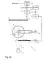
- FIGS 4A and 4B schematically show another embodiment of a tomography apparatus 1 according to the invention, which is similar to the embodiment shown in Figures 1A and 1B. Therefore, reference is made to the above description in order to avoid unnecessary repetitions. Further, the same reference numerals are used in the following description.
- shutter 7 is disposed in the path of the radiation 3 between the radiations source 2 and the object 4.
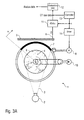
- FIG. 5 schematically shows another embodiment of the invention.
- This embodiment also comprises a rotary carrier 14 receiving in object 15, e.g. a human body, which is to be analysed.
- object 15 e.g. a human body
- the rotary carrier 14 along with the object 15 is rotated around an axis of rotation being aligned perpendicular to the plane of the drawing.
- the tomography apparatus comprises a radiation source 16 emitting radiation 17 in the direction of the object 15 so that the radiation 17 is transmitted through and attenuated by the object 15.
- the tomography apparatus comprises a pot-shaped radiation detector consisting of five separate radiation detectors 18-22 surrounding the object 15.
- the inner circumferential surface of the pot-shaped detectors 18-22 is partially shielded by a stationary shutter 23.
Landscapes
- Physics & Mathematics (AREA)
- Health & Medical Sciences (AREA)
- Life Sciences & Earth Sciences (AREA)
- General Physics & Mathematics (AREA)
- High Energy & Nuclear Physics (AREA)
- Molecular Biology (AREA)
- Spectroscopy & Molecular Physics (AREA)
- Analysing Materials By The Use Of Radiation (AREA)
Priority Applications (4)
| Application Number | Priority Date | Filing Date | Title |
|---|---|---|---|
| EP06013850A EP1876471A1 (fr) | 2006-07-04 | 2006-07-04 | Dispositif et procédé d'imagerie |
| US12/306,347 US7835487B2 (en) | 2006-07-04 | 2007-07-04 | Imaging apparatus and imaging method |
| PCT/EP2007/005919 WO2008003476A2 (fr) | 2006-07-04 | 2007-07-04 | Appareil d'imagerie et procédé d'imagerie |
| EP07785896A EP2035862A2 (fr) | 2006-07-04 | 2007-07-04 | Appareil d'imagerie et procédé d'imagerie |
Applications Claiming Priority (1)
| Application Number | Priority Date | Filing Date | Title |
|---|---|---|---|
| EP06013850A EP1876471A1 (fr) | 2006-07-04 | 2006-07-04 | Dispositif et procédé d'imagerie |
Publications (1)
| Publication Number | Publication Date |
|---|---|
| EP1876471A1 true EP1876471A1 (fr) | 2008-01-09 |
Family
ID=37492312
Family Applications (2)
| Application Number | Title | Priority Date | Filing Date |
|---|---|---|---|
| EP06013850A Withdrawn EP1876471A1 (fr) | 2006-07-04 | 2006-07-04 | Dispositif et procédé d'imagerie |
| EP07785896A Withdrawn EP2035862A2 (fr) | 2006-07-04 | 2007-07-04 | Appareil d'imagerie et procédé d'imagerie |
Family Applications After (1)
| Application Number | Title | Priority Date | Filing Date |
|---|---|---|---|
| EP07785896A Withdrawn EP2035862A2 (fr) | 2006-07-04 | 2007-07-04 | Appareil d'imagerie et procédé d'imagerie |
Country Status (3)
| Country | Link |
|---|---|
| US (1) | US7835487B2 (fr) |
| EP (2) | EP1876471A1 (fr) |
| WO (1) | WO2008003476A2 (fr) |
Families Citing this family (3)
| Publication number | Priority date | Publication date | Assignee | Title |
|---|---|---|---|---|
| US8520800B2 (en) * | 2010-08-09 | 2013-08-27 | Triple Ring Technologies, Inc. | Method and apparatus for radiation resistant imaging |
| JP2015194423A (ja) * | 2014-03-31 | 2015-11-05 | 株式会社日立ハイテクサイエンス | X線透過検査装置 |
| US12253479B1 (en) * | 2021-12-08 | 2025-03-18 | Jaywant Philip Parmar | Space-based x-ray imaging system |
Citations (4)
| Publication number | Priority date | Publication date | Assignee | Title |
|---|---|---|---|---|
| US4190773A (en) * | 1977-07-01 | 1980-02-26 | Braden Arthur B | Shutter for rotating source CT scanner |
| SU881590A1 (ru) * | 1980-02-22 | 1981-11-15 | Всесоюзный заочный машиностроительный институт | Рентгеновский вычислительный томограф |
| EP0223432A2 (fr) * | 1985-11-14 | 1987-05-27 | Shih-Ping Wang | Système de radiographie à rayons X |
| WO2001023910A2 (fr) * | 1999-09-27 | 2001-04-05 | British Nuclear Fuels Plc | Ameliorations apportees a des procedes et a un appareil permettant d'examiner des emissions |
Family Cites Families (1)
| Publication number | Priority date | Publication date | Assignee | Title |
|---|---|---|---|---|
| US7310404B2 (en) * | 2004-03-24 | 2007-12-18 | Canon Kabushiki Kaisha | Radiation CT radiographing device, radiation CT radiographing system, and radiation CT radiographing method using the same |
-
2006
- 2006-07-04 EP EP06013850A patent/EP1876471A1/fr not_active Withdrawn
-
2007
- 2007-07-04 WO PCT/EP2007/005919 patent/WO2008003476A2/fr not_active Ceased
- 2007-07-04 EP EP07785896A patent/EP2035862A2/fr not_active Withdrawn
- 2007-07-04 US US12/306,347 patent/US7835487B2/en not_active Expired - Fee Related
Patent Citations (4)
| Publication number | Priority date | Publication date | Assignee | Title |
|---|---|---|---|---|
| US4190773A (en) * | 1977-07-01 | 1980-02-26 | Braden Arthur B | Shutter for rotating source CT scanner |
| SU881590A1 (ru) * | 1980-02-22 | 1981-11-15 | Всесоюзный заочный машиностроительный институт | Рентгеновский вычислительный томограф |
| EP0223432A2 (fr) * | 1985-11-14 | 1987-05-27 | Shih-Ping Wang | Système de radiographie à rayons X |
| WO2001023910A2 (fr) * | 1999-09-27 | 2001-04-05 | British Nuclear Fuels Plc | Ameliorations apportees a des procedes et a un appareil permettant d'examiner des emissions |
Also Published As
| Publication number | Publication date |
|---|---|
| US20090310738A1 (en) | 2009-12-17 |
| WO2008003476A3 (fr) | 2008-03-20 |
| WO2008003476A2 (fr) | 2008-01-10 |
| EP2035862A2 (fr) | 2009-03-18 |
| US7835487B2 (en) | 2010-11-16 |
Similar Documents
| Publication | Publication Date | Title |
|---|---|---|
| US6956925B1 (en) | Methods and systems for multi-modality imaging | |
| CN101664317B (zh) | X射线计算机断层摄影装置 | |
| US9194827B2 (en) | Scanning device using radiation beam for backscatter imaging and method thereof | |
| JP4753602B2 (ja) | 静止型コンピュータ断層撮影システム及び方法 | |
| US8199883B2 (en) | X-ray flux management device | |
| EP2573551B1 (fr) | Dispositif et procédé à rayons x pour réalisation d'image de rétro-dispersion | |
| US20140376692A1 (en) | Mitigation of radiation leakage via entry port and/or exit port of radiation system | |
| US20060050841A1 (en) | Computed tomography apparatus comprising a fade-in device at the emitter end, and method for operating such a computed tomography apparatus | |
| CN101501530A (zh) | 用于获得图像数据的系统和方法 | |
| GB2084829A (en) | Flying spot scanner having arbitrarily shaped field size | |
| CN101410727A (zh) | 高效的双能x射线衰减测量 | |
| JP2003061951A (ja) | コンピュータトモグラフィ装置 | |
| US12442779B2 (en) | Systems and methods for inspection portals | |
| JP2014180541A (ja) | 制御装置及び制御プログラム | |
| US7835487B2 (en) | Imaging apparatus and imaging method | |
| JPH05168616A (ja) | X線ct装置 | |
| US20080267476A1 (en) | Method and system for reconstructing image volumes from helical scan acquisitiions | |
| EP0188782B1 (fr) | Procédé et dispositif de visualisation en radiographie sectionnelle | |
| JPH08275937A (ja) | X線断層撮影方法および装置 | |
| KR101712357B1 (ko) | 다중 라디오그래피 장치 | |
| JPH01254148A (ja) | X線ctスキヤナ | |
| JP2825253B2 (ja) | 放射線検出器 | |
| JP3231059B2 (ja) | 散乱線画像化装置 | |
| CN117280250A (zh) | 具有增大的分辨率的x射线检测器、装置及其方法 | |
| JPH04297241A (ja) | X線ct装置 |
Legal Events
| Date | Code | Title | Description |
|---|---|---|---|
| PUAI | Public reference made under article 153(3) epc to a published international application that has entered the european phase |
Free format text: ORIGINAL CODE: 0009012 |
|
| AK | Designated contracting states |
Kind code of ref document: A1 Designated state(s): AT BE BG CH CY CZ DE DK EE ES FI FR GB GR HU IE IS IT LI LT LU LV MC NL PL PT RO SE SI SK TR |
|
| AX | Request for extension of the european patent |
Extension state: AL BA HR MK YU |
|
| RAP1 | Party data changed (applicant data changed or rights of an application transferred) |
Owner name: HELMHOLTZ ZENTRUM MUENCHEN DEUTSCHES F |
|
| AKX | Designation fees paid | ||
| STAA | Information on the status of an ep patent application or granted ep patent |
Free format text: STATUS: THE APPLICATION IS DEEMED TO BE WITHDRAWN |
|
| 18D | Application deemed to be withdrawn |
Effective date: 20080710 |
|
| REG | Reference to a national code |
Ref country code: DE Ref legal event code: 8566 |