EP1876879A2 - Classification de composants amovibles pour le garnissage de supports de composants - Google Patents
Classification de composants amovibles pour le garnissage de supports de composants Download PDFInfo
- Publication number
- EP1876879A2 EP1876879A2 EP07109211A EP07109211A EP1876879A2 EP 1876879 A2 EP1876879 A2 EP 1876879A2 EP 07109211 A EP07109211 A EP 07109211A EP 07109211 A EP07109211 A EP 07109211A EP 1876879 A2 EP1876879 A2 EP 1876879A2
- Authority
- EP
- European Patent Office
- Prior art keywords
- component
- offset
- reference value
- components
- holding device
- Prior art date
- Legal status (The legal status is an assumption and is not a legal conclusion. Google has not performed a legal analysis and makes no representation as to the accuracy of the status listed.)
- Granted
Links
Images

Classifications
-
- H—ELECTRICITY
- H05—ELECTRIC TECHNIQUES NOT OTHERWISE PROVIDED FOR
- H05K—PRINTED CIRCUITS; CASINGS OR CONSTRUCTIONAL DETAILS OF ELECTRIC APPARATUS; MANUFACTURE OF ASSEMBLAGES OF ELECTRICAL COMPONENTS
- H05K13/00—Apparatus or processes specially adapted for manufacturing or adjusting assemblages of electric components
- H05K13/04—Mounting of components, e.g. of leadless components
- H05K13/0404—Pick-and-place heads or apparatus, e.g. with jaws
- H05K13/0413—Pick-and-place heads or apparatus, e.g. with jaws with orientation of the component while holding it; Drive mechanisms for gripping tools, e.g. lifting, lowering or turning of gripping tools
-
- H—ELECTRICITY
- H05—ELECTRIC TECHNIQUES NOT OTHERWISE PROVIDED FOR
- H05K—PRINTED CIRCUITS; CASINGS OR CONSTRUCTIONAL DETAILS OF ELECTRIC APPARATUS; MANUFACTURE OF ASSEMBLAGES OF ELECTRICAL COMPONENTS
- H05K13/00—Apparatus or processes specially adapted for manufacturing or adjusting assemblages of electric components
- H05K13/08—Monitoring manufacture of assemblages
- H05K13/081—Integration of optical monitoring devices in assembly lines; Processes using optical monitoring devices specially adapted for controlling devices or machines in assembly lines
- H05K13/0813—Controlling of single components prior to mounting, e.g. orientation, component geometry
Definitions
- the invention relates to the assembly of component carriers with components by means of so-called placement machines.
- the invention relates to a method for classifying an electronic component accommodated by a holding device for the purpose of faultless assembly of a component carrier with the component.
- the present invention further relates to a placement machine, which is set up for carrying out the method according to the invention for classifying a recorded electronic component.
- the invention relates to a computer-readable storage medium and a program element, which contain instructions for carrying out the method according to the invention for classifying a recorded component.
- components are provided by a component feeder at certain pickup positions and picked up by a placement, which can be freely positioned by means of a positioning within a workspace.
- the fetched components are transported from the placement to a placement position and placed on the component carrier to be fitted to defined by corresponding pads installation positions.
- miniaturization does not only affect the size of the electronic components.
- the distances between the component mounting positions on a component carrier or on a printed circuit board are always chosen smaller.
- the minimum feasible in practice distance of the components on the component carrier is determined in addition to the placement accuracy of the placement also by the Abholgenaumaschine.
- pick-up accuracy in this context means the spatial accuracy with which a component is received by a component holding device. If a small component of the holding device is not centrally received but with a lateral offset, then there is the risk that a laterally projecting part of the tip of the holding device touches an already equipped neighboring component when placing the device on the component carrier. In this case, the neighboring component may be damaged and / or displaced from its predetermined installation position, so that the result is a faulty assembly of the component carrier.
- the offset of the recorded components to the holding device for example, checked by a vision system and, if an allowable offset is exceeded, the device is discarded.
- the offset of a recorded component is determined by the fact that the corresponding holding device is rotated in the field of vision of a vision system about its longitudinal axis and thereby an optionally eccentric rotational movement of the component is detected.
- the offset of the component center is detected relative to the axis of rotation of the holding device.
- the axis of rotation can not coincide exactly with the axis of symmetry of the holding device, in particular with a slight curvature or bending of the holding device.
- the detected offset is compared with a so-called packaging tolerance, which is a measure of possible tolerances in the pick-up process of the component.
- the packaging tolerance is determined in particular by the size of so-called.
- Component pockets, in which the components to be supplied are individually packaged, for example in a component belt.
- the optimal pick-up position of the holding device can be determined above a component pocket based on the position of already picked and measured components. It is assumed that the device is within the packaging tolerance. With each successful retrieval attempt and the result of the position or offset measurement, the pick-up position of the holding device for the next component is improved. In this way, the offset of the component after only a few pick-ups only a fraction of the packaging tolerance.
- the invention has for its object to provide a method for classifying the offset of recorded by means of a holding device components, which allows both for small components both a high process reliability and an effective learning process with respect to the pickup positions of subsequent components.
- the cited method is based on the finding that even components that can not be used for reliable assembly due to high requirements with regard to the offset between the component and the holding device and therefore have to be removed from the placement process, have a learning process with respect to expected pick-up positions can be used for subsequent components. In this way, the duration of the learning process can be shortened considerably, so that significantly fewer components have to be discarded in comparison with known learning methods for as central a component pick-up as possible.
- the term offset may in this context be understood to mean a distance of the picked-up component, in particular a reference point or a reference axis of the recorded component, to a desired position of the component on the holding device.
- the offset may be a distance of the picked-up component, in particular a reference point or a reference axis of the recorded component, to the holding element, in particular to a reference point or a reference axis of the holding element.
- the term offset in this context means a distance between the middle of the component and the tip of the holding device on which the component is received.
- the tip of the holding device can be preferably defined by the symmetry axis of the holding device with respect to the outer contour of the holding device. In the case of a curvature of the holding device, for example, the outer contour can continue to be decisive on the end of the holding device facing a component that is received.
- the holding device can not be lowered at arbitrary locations of the component carrier without possibly damaging or displacing already assembled components.
- the ability of a placement machine to attach a device close to an already populated device is directly related to the offset between the device center and the tip of the fixture.
- offset does not mean the distance between the center of the component and the axis of rotation of the holding device. On the assumption of a central component recording, such an offset could namely be compensated for by a corresponding positioning of the holding device parallel to the surface of the component carrier.
- determining the offset requires two separate position detections.
- the position of the tip of the holding device is measured.
- the position of a recorded component is measured. The offset then results from a difference between the two measured positions.
- the first reference value is larger than the second reference value.
- the offset is determined only in terms of the amount and that the direction of the offset is not taken into account.
- both the first and second reference values are positive.
- a second classification condition with respect to the offset of the recorded component is specified.
- the device is classified as a device to be populated and the determined offset is used for the learning process with respect to the expected pickup positions of future devices. This case will occur in particular frequently if the learning process has already progressed so far that most of the components are picked up by the holding device with only a small offset.
- a third classification condition with respect to the offset of the recorded component is specified. Thus, if the offset is greater than the first reference value, the device is classified as a device to be discarded.
- the offset can also be so great that, in the case of a supposed component detection, the recorded component is also located outside of a predetermined detection range of the sensor device and thus is not or only partially detected becomes. In this case, it is assumed that the offset is in any case greater than the first reference value.
- the sensor device is an optical sensor device.
- the sensor device is a camera having, for example, a CCD sensor chip.
- the camera can provide analog or preferably digital image data, which are transferred by means of a suitable signal line to the evaluation unit.
- the sensor device may also comprise tactile sensors, capacitive sensors, inductive sensors and / or ultrasound sensors.
- the first reference value is selected depending on the accuracy with which the device is provided at the pick-up position.
- the first reference value is dependent in particular on the packaging of the component during the component feed and on the stability of the component feed by a corresponding component feed device.
- the supplied components are typically stored individually in so-called component pockets of a component belt.
- the sizes of the component pockets are therefore particularly relevant for the first reference value.
- the first reference value can therefore be referred to as packaging tolerance.
- the second reference value is selected depending on the distances between adjacent component slots of a component carrier to be populated.
- the second reference value is selected so that the offset between the holding device and the recorded component can be smaller for processing of the picked-up component must as the distance between an already equipped component and the space provided for the recorded component slot on the component carrier.
- the second reference value can thus also be referred to as offset tolerance.
- a value is selected for the second reference value or for the offset tolerance, which is the smaller, the smaller the spacing of the intended or already used component bays.
- the second reference value is therefore a parameter of the component carrier to be populated or of the spatial distribution of the component mounting positions arranged on the component carrier.
- the placement accuracy of the placement machine used always causes a certain blur with respect to the position of an already assembled component.
- this blurring must be taken into account when choosing the second reference value in order to reliably ensure collision-free component placement.
- the second reference value the smaller the value, the greater the placement accuracy of the already assembled component.
- the placement accuracy can be eliminated by performing a separate position measurement of the assembled component. In this case, then only the corresponding measurement accuracy is to be considered when choosing the second reference value.
- the second reference value is selected depending on the placement position respectively provided on the component carrier for the picked-up component. This means that the second reference value not only a characteristic of the component carrier to be equipped but a characteristic for an individual placement position on the component carrier.
- component carriers can be equipped with a particularly low reject rate of components.
- the second reference value or the offset tolerance is therefore chosen only as small as absolutely necessary for a reliable assembly of the respective component.
- a suitable placement position is selected on the component carrier depending on the measured offset for the recorded component. This means that, in particular in the assembly of printed circuit boards with a plurality of similar components, the placement program is dynamically adjusted depending on the respectively measured offset.
- a slot is selected for each recorded component, which allows a reliable and error-free assembly despite a previously determined offset. Accordingly, a recorded with a comparatively large offset component instead of a fault can be fitted to certain mounting positions, which should not yet be occupied according to the intended placement program, but due to a relatively large spacing to adjacent components an error-free assembly even with a large offset allow recorded components.
- the reject rate of electronic components can be further reduced in an advantageous manner.
- the holding device is a suction gripper.
- the element facing the tip of the suction pad is used to determine the offset between the device and the suction pad.
- the spatial position of the tip is determined on the basis of the symmetry axis of the outer contour of the suction pad. This has the advantage that the spatial position of the center of the suction pad or pipette tip can be determined particularly accurately.
- the outer contour of the suction cup tip itself or the outer contour of the suction cup can be used on an outer circumference of the suction gripper spaced from the suction cup tip. Since suction pipettes typically have an at least partially conical shape, the offset between the component and the suction gripper can also be reliably determined even if the component is larger than the tip of the suction gripper.
- a placement device for automatic placement of component carriers is created with components.
- the placement device has a processor which is set up such that the above-mentioned method for classifying a component received by a holding device can be carried out.
- a computer-readable storage medium in which a processing program for a placement machine for loading component carriers is stored with components.
- the program is executed by a processor, the above-described method of classifying an electronic component accommodated by a holder can be performed.
- Independent claim 13 describes a program element for equipping component carriers with components.
- the program element is executed by a processor, the above-described method of classifying an electronic component accommodated by a holder can be performed.
- the program element may be implemented as a computer-readable instruction code in any suitable programming language such as JAVA, C ++, etc.
- the program element can be stored on a computer-readable storage medium (CD-ROM, DVD, removable drive, volatile or non-volatile memory, built-in memory / processor, etc.).
- the instruction code may program a computer or other programmable device to perform the desired functions.
- the program element may be provided in a network, such as the Internet, from where it can be downloaded by a user as needed.
- the invention can be implemented both by means of a computer program, i. software, as well as by means of one or more special electrical circuits, i. in hardware or in any hybrid form, i. using software components and hardware components.
- FIG. 1 shows a placement machine 100 which has a frame 102 on which two parallel aligned guides 103 are mounted.
- the two guides 103 carry a transverse support arm 104.
- the transverse support arm 104 itself has a guide 105, on which a support member 106 is slidably mounted.
- the two guides 103 extend along a y-direction, the Guide 105 runs along an x-direction.
- a placement head 107 is arranged, which has at least one designed as a suction pipette 120 holding device, which is displaceable by means of a drive, not shown, along a direction perpendicular to the x and y direction z direction.
- the placement machine 100 also has a component feed device 112, via which components not shown in FIG. 1 can be supplied to the placement process. Furthermore, the placement machine 100 comprises a conveyor belt 131, with which a printed circuit board 130 can be introduced into the placement area. The suction pipette 107 can be positioned within the entire placement area by a corresponding movement of the placement head 107 within the x-y plane.
- the placement machine 100 also has a processor or a control unit 101.
- a machining program for the placement machine 100 for equipping component carriers can be executed with components, so that all components of the placement machine 100 work in a synchronized manner and thus contribute to a faultless and rapid placement of component carriers with components.
- Printed circuit board camera 140 is additionally attached, which is provided for detecting a mounted on the circuit board 130 marking 132. In this way, the exact position of the introduced in the Be Published Scheme printed circuit board 130 by a position measurement the marker 132 within the field of view of the printed circuit board camera 140 are determined.
- a camera 150 is provided, which is arranged according to the embodiment shown here in a fixed position on the placement machine 100.
- the optical component measurement is preferably carried out immediately after receiving the component from the component feeder 110 by a corresponding positioning of the placement head 107 above the component camera 150.
- the image recorded by the camera 150 is evaluated in an evaluation unit 151 and thereby the offset of the suction pipette 120 recorded component relative to the suction pipette determined.
- the evaluation unit 151 can also be integrated in the control unit 101 controlling the placement machine 100.
- the evaluation unit 151 can be realized by means of its own hardware or else by means of suitable software.
- the invention is by no means limited to use in the placement machine 100 shown here.
- the invention can also be realized for example with a component camera, which is moved together with the placement head and which is intended to measure the recorded components during transport from the receiving position to the placement position.
- the invention can be used in connection with a so-called. Multiple placement head, which has a plurality of holding devices and thus can simultaneously transport a plurality of components.
- the holding devices can be arranged in rows or in a matrix.
- the holding devices may also be arranged so as to be radially projecting about an axis of rotation, so that they can be separated by a rotation axis Rotation of the holding devices a plurality of components can be added sequentially and also discontinued.
- the invention can also be implemented with any other types of single or multiple placement heads.
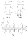
- FIG. 2a shows an ideal central reception of a component 211 by means of a suction pipette 220.
- the symmetry axis 221 of the suction pipette 220 and the axis of symmetry 215 of the component 211 coincide.
- the suction pipette 220 has no ovality.
- the axis of rotation 222 of the suction pipette 220 coincides with the symmetry or central axis 221 of the suction pipette 220.
- the suction pipette 220 has a substantially conical shape, wherein the cross section of the suction pipette 220 tapers perpendicular to the central axis 221 in the direction of a tip 225 of the suction pipette 220.
- a possible offset between the component 211 and the central axis 221 can be determined even if the cross section of the component 211 equal or even greater than the cross section of the pipette tip 225.
- the position of the device 211 is determined by the relative position between the center of the device 211 and an axis of symmetry of the outer contour 224 of the suction pipette 220. Due to the conical shape of the suction pipette 220, the outer contour is visible even when the component 211 is slightly larger or wider than the pipette tip 225.
- FIG. 2b shows a real eccentric recording of a component 211 by means of a suction pipette 220.
- the suction pipette 220 has a slight deformation such that the axis of symmetry 221 of the suction pipette 220 does not coincide with the axis of rotation 222 coincides.
- the suction pipette 220 rotates when an unillustrated hollow shaft, on which the suction pipette 220 is attached, is rotated about its longitudinal axis.
- the component 211 not accommodated in the center thus has an offset ⁇ relative to the suction pipette 220 which results from the distance between the axis of symmetry 215 of the component 211 and the axis of symmetry 221 of the suction pipette 220.
- This offset ⁇ is determined by means of a camera by a common detection of the component 211 and the outer contour 224 of the suction pipette 220.
- the determined offset ⁇ is compared with two reference values, a first reference value and a second reference value.
- the first reference value is selected according to the exemplary embodiment described here such that it is a measure of possible tolerances in the pick-up process of the component 211.
- the first reference value is determined, in particular, by the size of so-called component pockets, in which the components 211 to be supplied are packaged individually, for example in a component strap (not shown).
- the first reference value can thus also be referred to as packaging tolerance.
- the second reference value is selected according to the embodiment described here depending on the distances between adjacent component slots of a component carrier to be populated.
- the second reference value is so small that the offset between the suction pipette 220 and the accommodated component 211 must be smaller than the distance between an already equipped component and the installation space provided for the accommodated component 211 for equipping the accommodated component 211. In this way, a collision between the suction pipette 220 and already placed on the component carrier components are reliably prevented.
- the second reference value can thus also be referred to as offset tolerance.
- FIG. 3 shows a side view of a real actual arrangement 365 of components 311 populated next to one another which have been placed on a component carrier 330 by means of a sequential assembly by means of at least one suction pipette 320.
- the schematically and not to scale shown components 311 have the above-mentioned housing form 01005 and are equipped with a nominal distance of 100 .mu.m next to each other.
- the real positions 365 of the assembled components 311 are distributed statistically around their equidistant desired positions 360. This can lead to a laterally projecting part of the pipette tip 325 touching the immediately adjacent and already populated component 311 within a collision area when the component 311 shown on the left, which is received by the suction pipette 320 with a comparatively large offset. In particular, this contact can lead to this component being displaced, so that it is not contacted correctly with the connection surfaces provided on the printed circuit board 330 when the soldering operation following the assembly is finished.
- such a collision is prevented by the fact that the component is only equipped when the offset ⁇ is smaller than the offset tolerance.
Landscapes
- Engineering & Computer Science (AREA)
- Manufacturing & Machinery (AREA)
- Microelectronics & Electronic Packaging (AREA)
- Operations Research (AREA)
- Supply And Installment Of Electrical Components (AREA)
- Automatic Assembly (AREA)
- Magnetic Record Carriers (AREA)
- Electrochromic Elements, Electrophoresis, Or Variable Reflection Or Absorption Elements (AREA)
- Polishing Bodies And Polishing Tools (AREA)
Applications Claiming Priority (1)
| Application Number | Priority Date | Filing Date | Title |
|---|---|---|---|
| DE102006030292A DE102006030292A1 (de) | 2006-06-30 | 2006-06-30 | Klassifizierung von aufgenommenen Bauelementen bei der Bestückung von Bauelementeträgern |
Publications (3)
| Publication Number | Publication Date |
|---|---|
| EP1876879A2 true EP1876879A2 (fr) | 2008-01-09 |
| EP1876879A3 EP1876879A3 (fr) | 2008-07-02 |
| EP1876879B1 EP1876879B1 (fr) | 2010-05-12 |
Family
ID=38698883
Family Applications (1)
| Application Number | Title | Priority Date | Filing Date |
|---|---|---|---|
| EP07109211A Active EP1876879B1 (fr) | 2006-06-30 | 2007-05-30 | Classification de composants amovibles pour le garnissage de supports de composants |
Country Status (5)
| Country | Link |
|---|---|
| EP (1) | EP1876879B1 (fr) |
| JP (1) | JP4903091B2 (fr) |
| CN (1) | CN101098616B (fr) |
| AT (1) | ATE468010T1 (fr) |
| DE (2) | DE102006030292A1 (fr) |
Cited By (2)
| Publication number | Priority date | Publication date | Assignee | Title |
|---|---|---|---|---|
| EP3346813A4 (fr) * | 2015-09-01 | 2018-08-22 | Fuji Machine Mfg. Co., Ltd. | Dispositif de réglage de précision requise |
| EP3923693A4 (fr) * | 2019-02-05 | 2022-02-16 | Fuji Corporation | Dispositif de réglage de valeur admissible et procédé de réglage de valeur admissible |
Families Citing this family (1)
| Publication number | Priority date | Publication date | Assignee | Title |
|---|---|---|---|---|
| CN111911791A (zh) * | 2020-08-11 | 2020-11-10 | 天津天慧通科技股份有限公司 | 一种方便安装的智能摄像头 |
Family Cites Families (5)
| Publication number | Priority date | Publication date | Assignee | Title |
|---|---|---|---|---|
| US6230393B1 (en) * | 1997-07-07 | 2001-05-15 | Matsushita Electric Industrial Co., Ltd. | Method and device for mounting electronic component |
| JP3295655B2 (ja) * | 1999-03-30 | 2002-06-24 | 松下電器産業株式会社 | 電子部品の実装方法および実装装置 |
| DE60024375T2 (de) * | 1999-09-03 | 2006-06-14 | Matsushita Electric Industrial Co Ltd | Bauteilen-bestückungsverfahren und Einrichtung |
| JP2002050896A (ja) * | 2000-08-03 | 2002-02-15 | Sony Corp | 部品把持位置補正装置および補正方法 |
| US6718630B2 (en) * | 2000-09-18 | 2004-04-13 | Matsushita Electric Industrial Co., Ltd. | Apparatus and method for mounting components on substrate |
-
2006
- 2006-06-30 DE DE102006030292A patent/DE102006030292A1/de not_active Withdrawn
-
2007
- 2007-05-30 AT AT07109211T patent/ATE468010T1/de active
- 2007-05-30 DE DE502007003697T patent/DE502007003697D1/de active Active
- 2007-05-30 EP EP07109211A patent/EP1876879B1/fr active Active
- 2007-06-29 CN CN2007101262853A patent/CN101098616B/zh active Active
- 2007-06-29 JP JP2007172104A patent/JP4903091B2/ja active Active
Cited By (4)
| Publication number | Priority date | Publication date | Assignee | Title |
|---|---|---|---|---|
| EP3346813A4 (fr) * | 2015-09-01 | 2018-08-22 | Fuji Machine Mfg. Co., Ltd. | Dispositif de réglage de précision requise |
| US10935963B2 (en) | 2015-09-01 | 2021-03-02 | Fuji Corporation | Required accuracy setting device |
| EP3923693A4 (fr) * | 2019-02-05 | 2022-02-16 | Fuji Corporation | Dispositif de réglage de valeur admissible et procédé de réglage de valeur admissible |
| US12075568B2 (en) | 2019-02-05 | 2024-08-27 | Fuji Corporation | Allowable value setting device and allowable value setting method |
Also Published As
| Publication number | Publication date |
|---|---|
| EP1876879A3 (fr) | 2008-07-02 |
| DE102006030292A1 (de) | 2008-01-03 |
| JP4903091B2 (ja) | 2012-03-21 |
| CN101098616B (zh) | 2012-01-11 |
| EP1876879B1 (fr) | 2010-05-12 |
| JP2008016846A (ja) | 2008-01-24 |
| DE502007003697D1 (de) | 2010-06-24 |
| CN101098616A (zh) | 2008-01-02 |
| ATE468010T1 (de) | 2010-05-15 |
Similar Documents
| Publication | Publication Date | Title |
|---|---|---|
| DE69833476T2 (de) | Verfahren und Vorrichtung zur Montage eines elektronischen Bauteiles | |
| EP1470747B2 (fr) | Dispositif de prélèvement de puce, système d'équipement et procédé pour prélever des puces d'une plaquette | |
| DE112004002140T5 (de) | Bestückungsmaschine mit Bildaufnahmevorrichtung | |
| DE69901456T2 (de) | Verfahren und vorrichtung zum zuführen von bauteilen, und verfahren und einrichtung zur montage von bauteilen | |
| DE112005002446T5 (de) | Bestückungsmaschine mit verbesserter Bauteilaufnahmeprüfung | |
| WO2000067544A1 (fr) | Procede pour faire fonctionner un dispositif automatique de mise en place de composants, dispositif automatique de mise en place de composants, element interchangeable pour un tel dispositif, et systeme constitue d'un tel dispositif et d'un element interchangeable | |
| DE102011088321A1 (de) | Pneumatisches Bestimmen der Höhenlage eines Bauelements relativ zu einer Bauelement-Haltevorrichtung | |
| EP1876879B1 (fr) | Classification de composants amovibles pour le garnissage de supports de composants | |
| WO2000015017A1 (fr) | Procede et dispositif pour usiner des substrats | |
| DE102017116042B4 (de) | Verfahren und Bestückautomat zum Bestücken von Bauelementeträgern mit elektronischen Bauelementen | |
| DE102015106224B4 (de) | Verfahren zum wiederholten Vermessen eines in einem Bestückbereich eines Bestückautomaten befindlichen Bauelementeträgers sowie Bestückautomat und Computerprogramm zur Durchführung dieses Verfahrens | |
| DE102008037419A1 (de) | Vorrichtung und Verfahren zur Bestimmung der Position eines scheibenförmigen Objekts | |
| DE102016114842B4 (de) | Bauelement-Haltevorrichtung, Verfahren und Computerprogramm zum Bestücken eines Bauelementeträgers, Bestückautomat | |
| DE102020113002B3 (de) | Bestimmen der Genauigkeit einer Bestückmaschine bei mehrfacher Verwendung eines Test-Bauelements | |
| DE112021007148T5 (de) | Fremdkörpererkennungsvorrichtung und Fremdkörpererkennungsverfahren | |
| EP2116117B1 (fr) | Identification d'un composant électronique au moyen de différentes descriptions de composant | |
| DE202015106225U1 (de) | Vorrichtung zum automatisierten Abtrennen, Vereinzeln und Sortieren von bestückten und unbestückten Leiterplatten | |
| EP1260128B1 (fr) | Procede et dispositif permettant de determiner la position de prelevement de composants electriques dans un dispositif a planter les composants | |
| EP2579700B1 (fr) | Dispositif de support de composant avec un marquage apposé sur une paroi intérieure | |
| DE102016117472B4 (de) | Testvorrichtung zum Überprüfen einer Bestückfunktion eines Bestückautomaten, System aus einem Bestückautomat und einer Testvorrichtung sowie Verfahren zum Überprüfen einer Bestückfunktion eines Bestückautomaten | |
| DE102020115598B3 (de) | Verfahren und Bestückmaschine zum Bestücken von Bauelementeträgern basierend auf einem Rekalibrieren der Bestückmaschine im realen Bestückbetrieb, Computerprogramm zum Steuern einer Bestückmaschine | |
| DE102009043347B4 (de) | Verfahren zur Erkennung einer Pipettenkonfiguration für Bestückvorgänge | |
| DE102017216862B3 (de) | Bearbeitungsvorrichtung und Verfahren zum Betreiben einer Bearbeitungsvorrichtung | |
| DE112020007552T5 (de) | Fehlerursachenschätzvorrichtung und Fehlerursachenschätzverfahren | |
| DE69828280T2 (de) | Verfahren zum positionieren mindestens eines bauteils auf einer leiterplatte und vorrichtung um dieses verfahren durchzuführen |
Legal Events
| Date | Code | Title | Description |
|---|---|---|---|
| PUAI | Public reference made under article 153(3) epc to a published international application that has entered the european phase |
Free format text: ORIGINAL CODE: 0009012 |
|
| AK | Designated contracting states |
Kind code of ref document: A2 Designated state(s): AT BE BG CH CY CZ DE DK EE ES FI FR GB GR HU IE IS IT LI LT LU LV MC MT NL PL PT RO SE SI SK TR |
|
| AX | Request for extension of the european patent |
Extension state: AL BA HR MK YU |
|
| PUAL | Search report despatched |
Free format text: ORIGINAL CODE: 0009013 |
|
| AK | Designated contracting states |
Kind code of ref document: A3 Designated state(s): AT BE BG CH CY CZ DE DK EE ES FI FR GB GR HU IE IS IT LI LT LU LV MC MT NL PL PT RO SE SI SK TR |
|
| AX | Request for extension of the european patent |
Extension state: AL BA HR MK RS |
|
| 17P | Request for examination filed |
Effective date: 20081218 |
|
| AKX | Designation fees paid |
Designated state(s): AT BE BG CH CY CZ DE DK EE ES FI FR GB GR HU IE IS IT LI LT LU LV MC MT NL PL PT RO SE SI SK TR |
|
| 17Q | First examination report despatched |
Effective date: 20090303 |
|
| RAP1 | Party data changed (applicant data changed or rights of an application transferred) |
Owner name: SIEMENS ELECTRONICS ASSEMBLY SYSTEMS GMBH & CO. KG |
|
| GRAP | Despatch of communication of intention to grant a patent |
Free format text: ORIGINAL CODE: EPIDOSNIGR1 |
|
| GRAS | Grant fee paid |
Free format text: ORIGINAL CODE: EPIDOSNIGR3 |
|
| GRAA | (expected) grant |
Free format text: ORIGINAL CODE: 0009210 |
|
| AK | Designated contracting states |
Kind code of ref document: B1 Designated state(s): AT BE BG CH CY CZ DE DK EE ES FI FR GB GR HU IE IS IT LI LT LU LV MC MT NL PL PT RO SE SI SK TR |
|
| REG | Reference to a national code |
Ref country code: GB Ref legal event code: FG4D Free format text: NOT ENGLISH |
|
| REG | Reference to a national code |
Ref country code: CH Ref legal event code: EP |
|
| REG | Reference to a national code |
Ref country code: IE Ref legal event code: FG4D Free format text: LANGUAGE OF EP DOCUMENT: GERMAN |
|
| REF | Corresponds to: |
Ref document number: 502007003697 Country of ref document: DE Date of ref document: 20100624 Kind code of ref document: P |
|
| REG | Reference to a national code |
Ref country code: NL Ref legal event code: VDEP Effective date: 20100512 |
|
| LTIE | Lt: invalidation of european patent or patent extension |
Effective date: 20100512 |
|
| PG25 | Lapsed in a contracting state [announced via postgrant information from national office to epo] |
Ref country code: ES Free format text: LAPSE BECAUSE OF FAILURE TO SUBMIT A TRANSLATION OF THE DESCRIPTION OR TO PAY THE FEE WITHIN THE PRESCRIBED TIME-LIMIT Effective date: 20100823 Ref country code: NL Free format text: LAPSE BECAUSE OF FAILURE TO SUBMIT A TRANSLATION OF THE DESCRIPTION OR TO PAY THE FEE WITHIN THE PRESCRIBED TIME-LIMIT Effective date: 20100512 Ref country code: LT Free format text: LAPSE BECAUSE OF FAILURE TO SUBMIT A TRANSLATION OF THE DESCRIPTION OR TO PAY THE FEE WITHIN THE PRESCRIBED TIME-LIMIT Effective date: 20100512 Ref country code: SE Free format text: LAPSE BECAUSE OF FAILURE TO SUBMIT A TRANSLATION OF THE DESCRIPTION OR TO PAY THE FEE WITHIN THE PRESCRIBED TIME-LIMIT Effective date: 20100512 |
|
| BERE | Be: lapsed |
Owner name: SIEMENS ELECTRONICS ASSEMBLY SYSTEMS G.M.B.H. & CO Effective date: 20100531 |
|
| PG25 | Lapsed in a contracting state [announced via postgrant information from national office to epo] |
Ref country code: LV Free format text: LAPSE BECAUSE OF FAILURE TO SUBMIT A TRANSLATION OF THE DESCRIPTION OR TO PAY THE FEE WITHIN THE PRESCRIBED TIME-LIMIT Effective date: 20100512 Ref country code: IS Free format text: LAPSE BECAUSE OF FAILURE TO SUBMIT A TRANSLATION OF THE DESCRIPTION OR TO PAY THE FEE WITHIN THE PRESCRIBED TIME-LIMIT Effective date: 20100912 Ref country code: FI Free format text: LAPSE BECAUSE OF FAILURE TO SUBMIT A TRANSLATION OF THE DESCRIPTION OR TO PAY THE FEE WITHIN THE PRESCRIBED TIME-LIMIT Effective date: 20100512 Ref country code: SI Free format text: LAPSE BECAUSE OF FAILURE TO SUBMIT A TRANSLATION OF THE DESCRIPTION OR TO PAY THE FEE WITHIN THE PRESCRIBED TIME-LIMIT Effective date: 20100512 |
|
| REG | Reference to a national code |
Ref country code: IE Ref legal event code: FD4D |
|
| PG25 | Lapsed in a contracting state [announced via postgrant information from national office to epo] |
Ref country code: MC Free format text: LAPSE BECAUSE OF NON-PAYMENT OF DUE FEES Effective date: 20100531 Ref country code: PL Free format text: LAPSE BECAUSE OF FAILURE TO SUBMIT A TRANSLATION OF THE DESCRIPTION OR TO PAY THE FEE WITHIN THE PRESCRIBED TIME-LIMIT Effective date: 20100512 Ref country code: CY Free format text: LAPSE BECAUSE OF FAILURE TO SUBMIT A TRANSLATION OF THE DESCRIPTION OR TO PAY THE FEE WITHIN THE PRESCRIBED TIME-LIMIT Effective date: 20100519 |
|
| PG25 | Lapsed in a contracting state [announced via postgrant information from national office to epo] |
Ref country code: PT Free format text: LAPSE BECAUSE OF FAILURE TO SUBMIT A TRANSLATION OF THE DESCRIPTION OR TO PAY THE FEE WITHIN THE PRESCRIBED TIME-LIMIT Effective date: 20100913 Ref country code: DK Free format text: LAPSE BECAUSE OF FAILURE TO SUBMIT A TRANSLATION OF THE DESCRIPTION OR TO PAY THE FEE WITHIN THE PRESCRIBED TIME-LIMIT Effective date: 20100512 Ref country code: IE Free format text: LAPSE BECAUSE OF FAILURE TO SUBMIT A TRANSLATION OF THE DESCRIPTION OR TO PAY THE FEE WITHIN THE PRESCRIBED TIME-LIMIT Effective date: 20100512 Ref country code: EE Free format text: LAPSE BECAUSE OF FAILURE TO SUBMIT A TRANSLATION OF THE DESCRIPTION OR TO PAY THE FEE WITHIN THE PRESCRIBED TIME-LIMIT Effective date: 20100512 |
|
| PG25 | Lapsed in a contracting state [announced via postgrant information from national office to epo] |
Ref country code: SK Free format text: LAPSE BECAUSE OF FAILURE TO SUBMIT A TRANSLATION OF THE DESCRIPTION OR TO PAY THE FEE WITHIN THE PRESCRIBED TIME-LIMIT Effective date: 20100512 Ref country code: CZ Free format text: LAPSE BECAUSE OF FAILURE TO SUBMIT A TRANSLATION OF THE DESCRIPTION OR TO PAY THE FEE WITHIN THE PRESCRIBED TIME-LIMIT Effective date: 20100512 Ref country code: RO Free format text: LAPSE BECAUSE OF FAILURE TO SUBMIT A TRANSLATION OF THE DESCRIPTION OR TO PAY THE FEE WITHIN THE PRESCRIBED TIME-LIMIT Effective date: 20100512 |
|
| PLBE | No opposition filed within time limit |
Free format text: ORIGINAL CODE: 0009261 |
|
| STAA | Information on the status of an ep patent application or granted ep patent |
Free format text: STATUS: NO OPPOSITION FILED WITHIN TIME LIMIT |
|
| PG25 | Lapsed in a contracting state [announced via postgrant information from national office to epo] |
Ref country code: BE Free format text: LAPSE BECAUSE OF NON-PAYMENT OF DUE FEES Effective date: 20100531 Ref country code: IT Free format text: LAPSE BECAUSE OF FAILURE TO SUBMIT A TRANSLATION OF THE DESCRIPTION OR TO PAY THE FEE WITHIN THE PRESCRIBED TIME-LIMIT Effective date: 20100512 |
|
| 26N | No opposition filed |
Effective date: 20110215 |
|
| PG25 | Lapsed in a contracting state [announced via postgrant information from national office to epo] |
Ref country code: GR Free format text: LAPSE BECAUSE OF FAILURE TO SUBMIT A TRANSLATION OF THE DESCRIPTION OR TO PAY THE FEE WITHIN THE PRESCRIBED TIME-LIMIT Effective date: 20100813 Ref country code: MT Free format text: LAPSE BECAUSE OF FAILURE TO SUBMIT A TRANSLATION OF THE DESCRIPTION OR TO PAY THE FEE WITHIN THE PRESCRIBED TIME-LIMIT Effective date: 20100512 |
|
| REG | Reference to a national code |
Ref country code: DE Ref legal event code: R097 Ref document number: 502007003697 Country of ref document: DE Effective date: 20110214 |
|
| PG25 | Lapsed in a contracting state [announced via postgrant information from national office to epo] |
Ref country code: FR Free format text: LAPSE BECAUSE OF NON-PAYMENT OF DUE FEES Effective date: 20100712 |
|
| REG | Reference to a national code |
Ref country code: CH Ref legal event code: PL |
|
| GBPC | Gb: european patent ceased through non-payment of renewal fee |
Effective date: 20110530 |
|
| PG25 | Lapsed in a contracting state [announced via postgrant information from national office to epo] |
Ref country code: LI Free format text: LAPSE BECAUSE OF NON-PAYMENT OF DUE FEES Effective date: 20110531 Ref country code: CH Free format text: LAPSE BECAUSE OF NON-PAYMENT OF DUE FEES Effective date: 20110531 |
|
| PG25 | Lapsed in a contracting state [announced via postgrant information from national office to epo] |
Ref country code: GB Free format text: LAPSE BECAUSE OF NON-PAYMENT OF DUE FEES Effective date: 20110530 |
|
| PG25 | Lapsed in a contracting state [announced via postgrant information from national office to epo] |
Ref country code: BG Free format text: LAPSE BECAUSE OF FAILURE TO SUBMIT A TRANSLATION OF THE DESCRIPTION OR TO PAY THE FEE WITHIN THE PRESCRIBED TIME-LIMIT Effective date: 20100512 Ref country code: HU Free format text: LAPSE BECAUSE OF FAILURE TO SUBMIT A TRANSLATION OF THE DESCRIPTION OR TO PAY THE FEE WITHIN THE PRESCRIBED TIME-LIMIT Effective date: 20101113 Ref country code: LU Free format text: LAPSE BECAUSE OF NON-PAYMENT OF DUE FEES Effective date: 20100530 |
|
| PG25 | Lapsed in a contracting state [announced via postgrant information from national office to epo] |
Ref country code: TR Free format text: LAPSE BECAUSE OF FAILURE TO SUBMIT A TRANSLATION OF THE DESCRIPTION OR TO PAY THE FEE WITHIN THE PRESCRIBED TIME-LIMIT Effective date: 20100512 |
|
| REG | Reference to a national code |
Ref country code: AT Ref legal event code: MM01 Ref document number: 468010 Country of ref document: AT Kind code of ref document: T Effective date: 20120530 |
|
| PG25 | Lapsed in a contracting state [announced via postgrant information from national office to epo] |
Ref country code: AT Free format text: LAPSE BECAUSE OF NON-PAYMENT OF DUE FEES Effective date: 20120530 |
|
| PG25 | Lapsed in a contracting state [announced via postgrant information from national office to epo] |
Ref country code: BG Free format text: LAPSE BECAUSE OF FAILURE TO SUBMIT A TRANSLATION OF THE DESCRIPTION OR TO PAY THE FEE WITHIN THE PRESCRIBED TIME-LIMIT Effective date: 20100812 |
|
| REG | Reference to a national code |
Ref country code: DE Ref legal event code: R081 Ref document number: 502007003697 Country of ref document: DE Owner name: ASM ASSEMBLY SYSTEMS GMBH & CO. KG, DE Free format text: FORMER OWNER: SIEMENS ELECTRONICS ASSEMBLY SYSTEMS GMBH & CO. KG, 81379 MUENCHEN, DE |
|
| REG | Reference to a national code |
Ref country code: DE Ref legal event code: R081 Ref document number: 502007003697 Country of ref document: DE Owner name: ASMPT GMBH & CO. KG, DE Free format text: FORMER OWNER: ASM ASSEMBLY SYSTEMS GMBH & CO. KG, 81379 MUENCHEN, DE |
|
| P01 | Opt-out of the competence of the unified patent court (upc) registered |
Effective date: 20230530 |
|
| REG | Reference to a national code |
Ref country code: DE Ref legal event code: R082 Ref document number: 502007003697 Country of ref document: DE Representative=s name: DENNEMEYER & ASSOCIATES RECHTSANWALTSGESELLSCH, DE |
|
| PGFP | Annual fee paid to national office [announced via postgrant information from national office to epo] |
Ref country code: DE Payment date: 20250521 Year of fee payment: 19 |