EP1877314B1 - Procede de remplissage et dispositif de remplissage d'un reservoir de volume utile variable - Google Patents
Procede de remplissage et dispositif de remplissage d'un reservoir de volume utile variable Download PDFInfo
- Publication number
- EP1877314B1 EP1877314B1 EP06726324A EP06726324A EP1877314B1 EP 1877314 B1 EP1877314 B1 EP 1877314B1 EP 06726324 A EP06726324 A EP 06726324A EP 06726324 A EP06726324 A EP 06726324A EP 1877314 B1 EP1877314 B1 EP 1877314B1
- Authority
- EP
- European Patent Office
- Prior art keywords
- reservoir
- filling
- cannula
- fluid
- vacuum
- Prior art date
- Legal status (The legal status is an assumption and is not a legal conclusion. Google has not performed a legal analysis and makes no representation as to the accuracy of the status listed.)
- Expired - Lifetime
Links
Images

Classifications
-
- B—PERFORMING OPERATIONS; TRANSPORTING
- B65—CONVEYING; PACKING; STORING; HANDLING THIN OR FILAMENTARY MATERIAL
- B65B—MACHINES, APPARATUS OR DEVICES FOR, OR METHODS OF, PACKAGING ARTICLES OR MATERIALS; UNPACKING
- B65B31/00—Packaging articles or materials under special atmospheric or gaseous conditions; Adding propellants to aerosol containers
- B65B31/003—Adding propellants in fluid form to aerosol containers
-
- B—PERFORMING OPERATIONS; TRANSPORTING
- B65—CONVEYING; PACKING; STORING; HANDLING THIN OR FILAMENTARY MATERIAL
- B65B—MACHINES, APPARATUS OR DEVICES FOR, OR METHODS OF, PACKAGING ARTICLES OR MATERIALS; UNPACKING
- B65B3/00—Packaging plastic material, semiliquids, liquids or mixed solids and liquids, in individual containers or receptacles, e.g. bags, sacks, boxes, cartons, cans, or jars
- B65B3/04—Methods of, or means for, filling the material into the containers or receptacles
- B65B3/16—Methods of, or means for, filling the material into the containers or receptacles for filling collapsible tubes
-
- B—PERFORMING OPERATIONS; TRANSPORTING
- B65—CONVEYING; PACKING; STORING; HANDLING THIN OR FILAMENTARY MATERIAL
- B65B—MACHINES, APPARATUS OR DEVICES FOR, OR METHODS OF, PACKAGING ARTICLES OR MATERIALS; UNPACKING
- B65B31/00—Packaging articles or materials under special atmospheric or gaseous conditions; Adding propellants to aerosol containers
- B65B31/02—Filling, closing, or filling and closing, containers or wrappers in chambers maintained under vacuum or superatmospheric pressure or containing a special atmosphere, e.g. of inert gas
-
- B—PERFORMING OPERATIONS; TRANSPORTING
- B65—CONVEYING; PACKING; STORING; HANDLING THIN OR FILAMENTARY MATERIAL
- B65D—CONTAINERS FOR STORAGE OR TRANSPORT OF ARTICLES OR MATERIALS, e.g. BAGS, BARRELS, BOTTLES, BOXES, CANS, CARTONS, CRATES, DRUMS, JARS, TANKS, HOPPERS, FORWARDING CONTAINERS; ACCESSORIES, CLOSURES, OR FITTINGS THEREFOR; PACKAGING ELEMENTS; PACKAGES
- B65D83/00—Containers or packages with special means for dispensing contents
- B65D83/771—Containers or packages with special means for dispensing contents for dispensing fluent contents by means of a flexible bag or a deformable membrane or diaphragm
- B65D83/7711—Containers or packages with special means for dispensing contents for dispensing fluent contents by means of a flexible bag or a deformable membrane or diaphragm the contents of a flexible bag being expelled by the contracting forces inherent in the bag or a sleeve fitting snugly around the bag
-
- B—PERFORMING OPERATIONS; TRANSPORTING
- B65—CONVEYING; PACKING; STORING; HANDLING THIN OR FILAMENTARY MATERIAL
- B65B—MACHINES, APPARATUS OR DEVICES FOR, OR METHODS OF, PACKAGING ARTICLES OR MATERIALS; UNPACKING
- B65B7/00—Closing containers or receptacles after filling
- B65B7/16—Closing semi-rigid or rigid containers or receptacles not deformed by, or not taking-up shape of, contents, e.g. boxes or cartons
- B65B7/28—Closing semi-rigid or rigid containers or receptacles not deformed by, or not taking-up shape of, contents, e.g. boxes or cartons by applying separate preformed closures, e.g. lids, covers
- B65B7/2842—Securing closures on containers
- B65B7/2878—Securing closures on containers by heat-sealing
Definitions
- the present invention relates to a method of filling a reservoir of variable working volume with a fluid product.
- fluid product is meant as well liquid products more or less viscous, powdery products and gases.
- the present invention applies very generally to the field of fluid product packaging, and more particularly to the field of perfumery, cosmetics or pharmacy.
- the packaging is a vacuum packaging, or at least with a very small volume of air remaining inside the tank.
- a conventional flexible pouch filling technique is to inflate the compressed air pocket so that it offers a maximum capacity, or even greater than the volume to be introduced.
- a certain quantity of desired fluid product is then injected, the pump is prepositioned on the reservoir, then the entire packaging is placed with the pump in a vacuum chamber to evacuate the air. present in and on the surface of the fluid product already contained in the reservoir.
- a final step is to seal the pump on the tank. We can then break the vacuum.
- a filling variant consists in carrying out all the filling operations in a vacuum chamber.
- the present invention aims to overcome the aforementioned drawbacks of the prior art by defining a particularly simple filling process to implement, with a relatively simple tooling.
- the present invention provides a method of filling a tank of variable working volume with a fluid, corresponding to claim 1.
- the present invention provides for injecting the fluid into a reservoir while its useful volume is as zero as possible. This avoids trapping air inside the tank during the injection of the fluid. It is thus ensured that the tank is filled with fluid only, to the exclusion of all air. For this, we start from a tank whose useful volume is zero. It is indeed advantageous to maintain the volume of the reservoir substantially zero until the injection of the fluid product. For this, it is not necessary to let the vacuum pump run: simply isolate the tank from the outside. Once the tank is full, the tank can be returned to atmospheric pressure and the pump or valve can be sealed to the tank using any suitable fastening technique. It is not really necessary or essential for the tank to be located in a vacuum chamber when mounting the pump or valve, since the filling method according to the present invention ensures that the tank is fully and only filled. fluid, excluding all air.
- the head comprises a sleeve provided with sealing means on an opening of the reservoir and a vacuum outlet for connection to the vacuum source, and a fluid injection cannula that is slidably displaceable in the sleeve.
- the cannula is movable between two sealing stop positions in which the vacuum outlet does not communicate with the sealing means, the socket communicating with the sealing means when the cannula is between the stop positions.
- an evacuation path is defined between the sleeve and the cannula, the path connecting the vacuum connection to the sealing means, the cannula being elastically biased by return means in the high stop position and being displaceable at against the return means to the low stop position, the cannula being in position high before evacuation and in the low position after evacuation and during the injection of fluid product.
- the filling device makes it possible to succeed without interruption the injection step in the evacuation step.
- the displacement of the injection cannula inside the sleeve makes it possible to activate and deactivate the evacuation of the reservoir.
- the evacuation step is stopped. Between these two stops, evacuation is possible.
- the return means urges the injection cannula in the high abutment position, which corresponds to a rest position, in which evacuation is not possible.
- the evacuation is also not possible, since this corresponds to the step of injecting the fluid into the reservoir.
- the emptying / filling head is a relatively simple mechanical system, implementing only two moving parts relative to each other, under the action of a spring.
- This emptying / filling head can be mounted instead of a conventional filling head which operates only a conventional fluid injection step.
- the cannula comprises an outlet orifice provided with a shutter preventing the suction of fluid contained in the cannula, when the evacuation means are operative. It must indeed prevent the fluid is sucked through the sleeve to the vacuum pump, which could damage it.
- the filling device is shown associated with a packaging or container of variable useful volume of a particular type but well known.
- This packaging or container comprises a reservoir of variable useful volume 1 which is here in the form of a flexible bag which can for example be made from a complex film made of plastic and aluminum.
- This flexible pouch 11 defines an opening which is sealingly fixed, advantageously by heat sealing, on a pocket support 3.
- This pocket support comprises a fixing sleeve 31 engaged inside the opening 12 and a sleeve of anchor 32 which terminates in a flange 33 which protrudes radially outwards.
- the package or container comprises an outer rigid shell 2 which can be made of any rigid or substantially rigid material.
- the outer shell 2 comprises a bottom provided with a vent hole 23. At its opposite end, the shell 2 comprises a neck 22 which defines an opening 21.
- the pocket 11 is disposed inside the shell 2 with the support pocket 3 engaged with the neck 22.
- the sleeve 32 is housed inside the neck 22 with the projecting flange 33 which bears on the upper end edge of the neck 22.
- the vent hole 23 has the effect of communicating the space 12 between the shell 2 and the flexible bag 11 with the outside, so that the space 12 is always at atmospheric pressure.
- a deformable container instead of the flexible pouch fixed on a support, it is also possible to use a deformable container, an elastic bag, a follower piston system, or more generally any tank with variable useful volume.
- the filling device is only partially represented on the Figures 1 to 6 : Indeed, the filling device further comprises other elements or bodies not shown.
- the only part of the filling device shown in the figures is constituted by a dump / filling head which comes into direct contact with the packaging or container which has been previously described.
- the emptying / filling head must in fact still be provided with means for supporting and moving the head (not shown).
- the head must also be connected to a vacuum source (not shown) and a source of fluid (not shown).
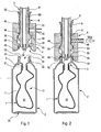
- the emptying / filling head shown on the Figures 1 to 6 comprises an outer sleeve 4 and an internal injection cannula 5.
- the sleeve 4 has a very generally cylindrical shape, thus defining a hollow interior, which can be divided into three parts generally, namely an upper duct 42, an intermediate chamber 43 and a sealing and injection mouth 47.
- the conduit 42 is provided near its upper end with a seal 41 which extends over the entire periphery of the conduit 42, and which is intended to come into sealing contact with the cannula 5, as it is will see below.
- the duct 42 is extended at its lower end by an upper stop seat 44, which also defines the inlet of the chamber 43.
- This chamber 43 here has a diameter greater than that of the duct 42, so that the seat of The upper stop 44 flares outwardly from the lower end of the duct 42.
- the chamber 43 narrows at a low abutment seat 45.
- This seat 45 like the seat 44, has a frustoconical shape that flares this time inwards, unlike the seat 44.
- the sleeve 4 is provided with annular sealing means 46 which is here in the form of an advantageously flat O-ring.
- the diameter of this O-ring is adapted to be able to come into sealing contact with the projecting flange 33 formed by the pocket support 3.
- the sealing and injection mouth 47 extends below this flat O-ring 46 and advantageously has a peripheral wall chamfered to facilitate the introduction of the reservoir, and more particularly of the collar 33, inside the mouth 47, until it comes into sealing engagement with the O-ring 46.
- the sleeve 4 is provided with a lateral vacuum outlet 48, which passes through the wall thickness of the sleeve 4, so as to directly communicate the conduit 42 laterally with the outside.
- This vacuum plug 48 is intended to be connected by means of a hose to a vacuum source (not shown), which may be a vacuum pump.
- the injection cannula 5 is in the form of a rod 51 having a hollow interior 50 defining a passage for the fluid product.
- the upper end of the cannula 5 is intended to be connected, via a suitable hose, to a source of fluid.
- the cannula 5 comprises a peripheral flange 52 which protrudes radially outwards.
- This flange 52 serves as a bearing surface for the return spring 6 which is engaged around the cannula 5 and bears on the other hand on the top of the sleeve 4.
- the cannula 5 thus also serves as guiding means for the coil spring 6 which extends around the cannula. It is thus understood that the cannula 5 is urged upwards by the return spring 6 relative to the sleeve 4.
- the cannula 5 extends through the sleeve 4, and more precisely through the conduit 42, and the chamber 43 to the level of the seal and injection port 47.
- the cannula 5 thus extends through the conduit 42 so as to slide inside the conduit 42 without sealing, except at the O-ring 41 which is sealingly sliding with the cannula 5. Except at this O-ring 41, the cannula 5 is not in sealing contact with the conduit 42.
- the cannula 5 preferably forms a substantially cylindrical section at the duct 42, which is itself substantially cylindrical.
- the cannula 5 forms a substantially annular peripheral bead 53 which protrudes radially outwards with respect to the cylindrical section engaged inside the conduit 42.
- another annular ring substantially frustoconical namely an upper ring 54 and a lower ring 55.
- the upper ring 54 flares downward while the lower ring 55 flares upwards.
- the projecting bead 53 is housed inside the chamber 43 formed by the sleeve 4.
- the upper ring 54 is intended to come into sealing contact with the high stop seat 44 formed by the sleeve 4.
- the crown lower 55 is intended to come into sealed contact with the low abutment seat 45 formed by the sleeve 4.
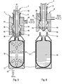
- the cord 53 is trapped in the sleeve 4 inside its chamber 43. It is therefore not possible to disengage the cannula from the inside of the sleeve 4 because the cord 53 is trapped in the chamber. 43. On the other hand, it is possible to axially move the cannula 5 inside the sleeve 4 against the action exerted by the return spring 6 between the two abutment seats 44 and 45. In rest position represented on the figure 1 , the upper ring 54 is in sealing contact with the high stop seat 44. On the other hand, on the figures 4 and 5 , the lower ring 55 is in sealing contact with the low abutment seat 45. Between these two sealed contacts, as shown in FIG.
- the cannula 5 there is no sealing between the cannula 5 and the sleeve 4, except at the O-ring 41.
- the cannula 5 extends with a reduced diameter section relative to the cord. 53.
- the diameter of this lower section may be substantially equal to that of the cylindrical section engaged inside the conduit 42.
- the cannula 5 forms a fluid outlet which is advantageously provided with a shutter 56 which is closed in the rest position, and also prevents any entry inside the cannula 5 through the shutter 56.
- the emptying / filling head of the filling device in the waiting position. Indeed, before starting any movement of the head of emptying / filling, it is first necessary to ensure that the packaging or container is perfectly positioned just below the head. It is necessary that the opening 21 of the reservoir is located axially just below the cannula 5. In general, the emptying / filling head is held and moved by the cannula 5. It is indeed not necessary to grasp the sleeve 4 for his displacement. In this waiting position, which ideally corresponds to the rest position of the head, the upper ring 54 is in sealing contact with the high stop seat 44. Thus, the vacuum outlet 48 can not communicate with the outside.
- the sleeve 4 will be even more pressed on the flange 33 until the return spring 6 does not start to contract.
- the vacuum source connected to the vacuum plug 48 can be activated. This is indicated by the annotated arrow EMP on the figure 2 .
- the vacuum state is represented on the figure 2 by oblique hatching spaced. The state of vacuum reaches the level of the annular space formed between the conduit 42 and the cannula 5. However, the vacuum does not reach into the chamber 43, because the ring 54 is in sealing contact with the seat 44. By continuing to press the cannula 5, this contact will be undone, which is represented on the figure 3 .
- the air present in the intermediate space 12 is discharged through the vent orifice 23.
- the shutter 56 is of course biased in the open position. Since the evacuation is stopped, the chamber 43 is at atmospheric pressure. This is indicated by the ATMO annotated arrow on the figure 5 . Since the bag was initially completely empty before injection, it is ensured that its fluid filling is perfect and total, excluding any air bubbles. In the end, the reservoir is as represented on the figure 6 . It is then possible to raise the head, that is to say to stop the pressure exerted on the cannula 5, so that the return spring 6 again urges the cannula 5 to the rest position, that is to say with its upper ring 54 in engagement with its seat 44. One finds oneself then again in the same position as that represented on the figure 1 .
- a subsequent step of sealing a pump or a valve on the tank is carried out.
- This mounting step can be performed under vacuum or not.
- the invention it is no longer necessary to operate the vacuum pump during the step of injecting the fluid into the tank. Indeed, in the present invention, when the fluid is injected into the tank, the evacuation is already stopped. However, the completely empty state of the tank is maintained.
Landscapes
- Engineering & Computer Science (AREA)
- Mechanical Engineering (AREA)
- Chemical & Material Sciences (AREA)
- Dispersion Chemistry (AREA)
- Basic Packing Technique (AREA)
- Vacuum Packaging (AREA)
- Containers And Packaging Bodies Having A Special Means To Remove Contents (AREA)
Applications Claiming Priority (2)
| Application Number | Priority Date | Filing Date | Title |
|---|---|---|---|
| FR0550926A FR2884225B1 (fr) | 2005-04-12 | 2005-04-12 | Procede de remplissage et dispositif de remplissage d'un reservoir de volume utile variable |
| PCT/FR2006/050318 WO2006108984A1 (fr) | 2005-04-12 | 2006-04-10 | Procede de remplissage et dispositif de remplissage d'un reservoir de volume utile variable |
Publications (2)
| Publication Number | Publication Date |
|---|---|
| EP1877314A1 EP1877314A1 (fr) | 2008-01-16 |
| EP1877314B1 true EP1877314B1 (fr) | 2011-03-02 |
Family
ID=35429457
Family Applications (1)
| Application Number | Title | Priority Date | Filing Date |
|---|---|---|---|
| EP06726324A Expired - Lifetime EP1877314B1 (fr) | 2005-04-12 | 2006-04-10 | Procede de remplissage et dispositif de remplissage d'un reservoir de volume utile variable |
Country Status (8)
| Country | Link |
|---|---|
| US (2) | US8061393B2 (pt) |
| EP (1) | EP1877314B1 (pt) |
| CN (1) | CN100586802C (pt) |
| BR (1) | BRPI0610548A2 (pt) |
| DE (1) | DE602006020429D1 (pt) |
| ES (1) | ES2360077T3 (pt) |
| FR (1) | FR2884225B1 (pt) |
| WO (1) | WO2006108984A1 (pt) |
Families Citing this family (26)
| Publication number | Priority date | Publication date | Assignee | Title |
|---|---|---|---|---|
| FR2884225B1 (fr) * | 2005-04-12 | 2007-06-22 | Airlessystems Soc Par Actions | Procede de remplissage et dispositif de remplissage d'un reservoir de volume utile variable |
| DE602008006064D1 (de) * | 2007-01-18 | 2011-05-19 | Eveready Battery Inc | Rasiersystem mit gaserzeugungszelle |
| EP2328821B1 (de) | 2008-08-01 | 2014-06-25 | Boehringer Ingelheim International GmbH | Verpackungseinheit mit einer kunststoffflasche und einem darin angeordneten folienbeutel |
| KR101301732B1 (ko) * | 2009-12-09 | 2013-08-28 | 도요 에어로졸 고교 가부시키가이샤 | 분사제의 충진장치 |
| US20110139295A1 (en) * | 2009-12-15 | 2011-06-16 | Scheindel Christian T | Pouch Support For A Pressurized Dispensing Container |
| JP5650242B2 (ja) | 2009-12-16 | 2015-01-07 | ベクトン・ディキンソン・アンド・カンパニーBecton, Dickinson And Company | 自己注射器具 |
| DK2512559T3 (en) | 2009-12-16 | 2019-03-25 | Becton Dickinson Co | SELF-INJECTIVE DEVICE |
| US8844584B1 (en) * | 2010-02-05 | 2014-09-30 | Bissell Homecare, Inc. | Apparatus and method for a pressurized dispenser refill system |
| CN102398690A (zh) * | 2010-09-14 | 2012-04-04 | 南通薄荷厂有限公司 | 真空液灌箱 |
| FR2964950B1 (fr) * | 2010-09-20 | 2012-08-31 | Bonduelle Sa Ets | Procede de conditionnement d'un produit liquide. |
| FR2987609B1 (fr) * | 2012-03-05 | 2015-07-24 | Lindal France Sas | Moyens antiaffaissement |
| DE102013101642A1 (de) * | 2013-02-19 | 2014-08-21 | Khs Gmbh | Verfahren und Vorrichtung zum Herstellen und Füllen von Behältern |
| EP2958437B1 (en) * | 2013-02-21 | 2020-02-05 | Direvo Industrial Biotechnology GmbH | Prebiotic animal feed product |
| DE102013204602A1 (de) * | 2013-03-15 | 2014-09-18 | Flecotec Ag | Flexibles Gebinde sowie Befüllvorrichtung für ein solches flexibles Gebinde und entsprechendes Befüllverfahren |
| DE102013022261B4 (de) * | 2013-12-06 | 2018-09-27 | Leibinger Gmbh | Vorrichtung zum Befüllen eines Behältnisses |
| DE102014104874A1 (de) * | 2014-04-04 | 2015-10-08 | Krones Ag | Vorrichtung und Verfahren zur Herstellung einer Kunststoffflasche und deren Befüllung mit einem Füllprodukt |
| JP6187512B2 (ja) * | 2015-03-17 | 2017-08-30 | コニカミノルタ株式会社 | トナー充填装置 |
| FR3066481B1 (fr) * | 2017-05-16 | 2020-10-16 | Fillon Technologies | Dispositif de commande en ouverture/fermeture d'une valve d'un recipient a valve, ensemble comprenant un recipient a valve et un tel dispositif de commande |
| EP3712087A4 (en) * | 2017-11-17 | 2021-07-21 | Innerbottle Co., Ltd. | CONTAINING DEVICE CAPABLE OF STORING A LIQUID AND ITS MANUFACTURING PROCESS |
| KR102164809B1 (ko) * | 2018-05-17 | 2020-10-14 | (주)이너보틀 | 용기 제조 방법 및 용기 제조 장치 |
| CN109436423B (zh) * | 2018-12-20 | 2024-01-23 | 普叶顿(上海)自动化科技有限公司 | 一种用于医疗器械的抽真空加注装置及其方法 |
| EP3915885A4 (en) * | 2019-02-21 | 2022-11-23 | Innerbottle Co., Ltd. | CONTENT FILLING DEVICE AND CONTENT FILLING METHOD WITH USE THEREOF |
| FR3093328B1 (fr) * | 2019-02-28 | 2021-02-19 | Bonduelle Sa Ets | Procédé de conditionnement de produits |
| US11945614B2 (en) * | 2019-05-08 | 2024-04-02 | Prc-Desoto International, Inc. | Sealant cartridge air release apparatus and methods |
| US20210078791A1 (en) * | 2019-09-13 | 2021-03-18 | The Procter & Gamble Company | Apparatus and Method of Making an Aerosol Dispenser |
| KR102614868B1 (ko) * | 2021-03-29 | 2023-12-19 | (주)이너보틀 | 내용물 충진장치 |
Family Cites Families (15)
| Publication number | Priority date | Publication date | Assignee | Title |
|---|---|---|---|---|
| US2564163A (en) * | 1943-01-12 | 1951-08-14 | Leperre Jean Emile Lucien | Receptacle with elastic bag insert and system for filling and emptying the same |
| US3995666A (en) * | 1975-12-24 | 1976-12-07 | Vca Corporation | Method for filling aerosol spray dispensers |
| US4150522A (en) * | 1977-03-07 | 1979-04-24 | Nicholas A. Mardesich | Method for undercap filling of a barrier pack aerosol container |
| US4481753A (en) * | 1981-12-17 | 1984-11-13 | Champion International Corporation | Bag filler-capper |
| US4501306A (en) * | 1982-11-09 | 1985-02-26 | Collagen Corporation | Automatic syringe filling system |
| US4896794A (en) * | 1987-09-11 | 1990-01-30 | Enviro-Spray Systems, Inc. | Method for prepressurizing dispensing container and for filling pressurized container with flowable product |
| FR2625729B1 (fr) * | 1988-01-08 | 1990-08-17 | Step Soc Tech Pulverisation | Dispositif de distribution de produit pateux |
| DE3923903A1 (de) * | 1989-07-19 | 1991-01-24 | Hirsch Anton | Verfahren zur befuellung von druckgaspackungen sowie druckgaspackung |
| FR2653744B1 (fr) * | 1989-10-31 | 1992-03-06 | Valois | Procede pour conditionner sous vide des produits notamment cosmetiques et pharmaceutiques a l'interieur de reservoirs deformables obtures par une pompe de distribution sans reprise d'air, dispositif pour le mettre en óoeuvre et distributeurs ainsi obt. |
| IT1293462B1 (it) * | 1997-07-18 | 1999-03-01 | Techpack Srl | Valvola riempitrice di contenitori flosci per liquidi viscosi. |
| CN1170732C (zh) * | 1998-06-29 | 2004-10-13 | 阿斯特拉帕克有限公司 | 无菌灌装容器的方法和装置及无菌容器及其插塞和封盖口 |
| JP4090579B2 (ja) * | 1998-07-14 | 2008-05-28 | 東洋エアゾール工業株式会社 | 二重エアゾール容器の製造方法及びこの製造方法により形成した二重エアゾール容器 |
| EP1284911B1 (en) * | 2000-05-19 | 2006-11-15 | The Gillette Company | System for dispensing multi-component products |
| ATE472473T1 (de) * | 2003-09-22 | 2010-07-15 | Battelle Memorial Institute | Behälterfüllanordnung |
| FR2884225B1 (fr) * | 2005-04-12 | 2007-06-22 | Airlessystems Soc Par Actions | Procede de remplissage et dispositif de remplissage d'un reservoir de volume utile variable |
-
2005
- 2005-04-12 FR FR0550926A patent/FR2884225B1/fr not_active Expired - Fee Related
-
2006
- 2006-04-10 ES ES06726324T patent/ES2360077T3/es not_active Expired - Lifetime
- 2006-04-10 EP EP06726324A patent/EP1877314B1/fr not_active Expired - Lifetime
- 2006-04-10 US US11/910,829 patent/US8061393B2/en not_active Expired - Fee Related
- 2006-04-10 DE DE602006020429T patent/DE602006020429D1/de not_active Expired - Lifetime
- 2006-04-10 WO PCT/FR2006/050318 patent/WO2006108984A1/fr not_active Ceased
- 2006-04-10 BR BRPI0610548-3A patent/BRPI0610548A2/pt not_active IP Right Cessation
- 2006-04-10 CN CN200680015461.XA patent/CN100586802C/zh not_active Expired - Fee Related
-
2011
- 2011-10-06 US US13/267,188 patent/US8479779B2/en not_active Expired - Fee Related
Also Published As
| Publication number | Publication date |
|---|---|
| DE602006020429D1 (de) | 2011-04-14 |
| FR2884225B1 (fr) | 2007-06-22 |
| EP1877314A1 (fr) | 2008-01-16 |
| FR2884225A1 (fr) | 2006-10-13 |
| WO2006108984A1 (fr) | 2006-10-19 |
| US8479779B2 (en) | 2013-07-09 |
| BRPI0610548A2 (pt) | 2010-07-06 |
| CN100586802C (zh) | 2010-02-03 |
| ES2360077T3 (es) | 2011-05-31 |
| CN101171175A (zh) | 2008-04-30 |
| US8061393B2 (en) | 2011-11-22 |
| US20120024419A1 (en) | 2012-02-02 |
| US20080156391A1 (en) | 2008-07-03 |
Similar Documents
| Publication | Publication Date | Title |
|---|---|---|
| FR2884225A1 (fr) | Procede de remplissage et dispositif de remplissage d'un reservoir de volume utile variable | |
| EP0509179B1 (fr) | Procédé pour conditionner sous vide des produits notamment cosmétiques et pharmaceutiques à l'intérieur de réservoirs de contenance variable obturés par un organe de distribution sans reprise d'air, dispositif pour le mettre en oeuvre | |
| EP2534068B1 (fr) | Distributeur de produit fluide | |
| EP2313319B1 (fr) | Procede de conditionnement de produit fluide dans un distributeur | |
| EP2170527B2 (fr) | Procede et dispositif de conditionnement de distributeur de produit fluide | |
| EP1572375B1 (fr) | Pompe doseuse a actionnement manuel | |
| FR2773355A1 (fr) | Dispositif de conditionnement et de distribution comportant un reservoir rempli sous vide et procede de fabrication | |
| EP1626813A2 (fr) | Distributeur de produit fluide et procede de montage d'un tel distributeur | |
| EP0857149A2 (fr) | Distributeur de produits liquides ou pateux | |
| EP0349396A1 (fr) | Procédé de conditionnement sous vide de liquides et de pâtes en tube souple avec valve ou pompe de distribution et dispositif pour sa mise en oeuvre | |
| EP0785824B1 (fr) | Procede de fabrication d'un flacon de distribution de fluide comprenant une poche souple | |
| EP2470429B1 (fr) | Ensemble et procede de conditionnement sous vide | |
| FR2685285A1 (fr) | Procede de conditionnement d'un produit liquide quelconque et flacon obtenu par ce procede. | |
| EP3573891B1 (fr) | Procede de fabrication d'un dispositif distributeur de produit | |
| FR2668119A2 (fr) | Procede de conditionnement sous vide en distributeurs a enveloppe rigide et distributeurs correspondants. | |
| WO2014184483A1 (fr) | Distributeur de produit fluide | |
| EP3490406B1 (fr) | Dispositif de prelevement et d'application de produit fluide | |
| EP4448189A1 (fr) | Procédé et système de recharge en liquide d'un flacon | |
| FR2561546A1 (fr) | Procede pour le conditionnement de silicone, poche pour sa mise en oeuvre et machine pour l'extrusion de cordons de silicone | |
| FR3066478A1 (fr) | Ensemble destine au conditionnement d'un produit fluidique |
Legal Events
| Date | Code | Title | Description |
|---|---|---|---|
| PUAI | Public reference made under article 153(3) epc to a published international application that has entered the european phase |
Free format text: ORIGINAL CODE: 0009012 |
|
| 17P | Request for examination filed |
Effective date: 20071109 |
|
| AK | Designated contracting states |
Kind code of ref document: A1 Designated state(s): DE ES FR GB IT |
|
| DAX | Request for extension of the european patent (deleted) | ||
| RBV | Designated contracting states (corrected) |
Designated state(s): DE ES FR GB IT |
|
| 17Q | First examination report despatched |
Effective date: 20081111 |
|
| GRAP | Despatch of communication of intention to grant a patent |
Free format text: ORIGINAL CODE: EPIDOSNIGR1 |
|
| GRAS | Grant fee paid |
Free format text: ORIGINAL CODE: EPIDOSNIGR3 |
|
| GRAA | (expected) grant |
Free format text: ORIGINAL CODE: 0009210 |
|
| AK | Designated contracting states |
Kind code of ref document: B1 Designated state(s): DE ES FR GB IT |
|
| REG | Reference to a national code |
Ref country code: GB Ref legal event code: FG4D Free format text: NOT ENGLISH |
|
| REF | Corresponds to: |
Ref document number: 602006020429 Country of ref document: DE Date of ref document: 20110414 Kind code of ref document: P |
|
| REG | Reference to a national code |
Ref country code: DE Ref legal event code: R096 Ref document number: 602006020429 Country of ref document: DE Effective date: 20110414 |
|
| REG | Reference to a national code |
Ref country code: ES Ref legal event code: FG2A Ref document number: 2360077 Country of ref document: ES Kind code of ref document: T3 Effective date: 20110531 |
|
| PLBE | No opposition filed within time limit |
Free format text: ORIGINAL CODE: 0009261 |
|
| STAA | Information on the status of an ep patent application or granted ep patent |
Free format text: STATUS: NO OPPOSITION FILED WITHIN TIME LIMIT |
|
| 26N | No opposition filed |
Effective date: 20111205 |
|
| REG | Reference to a national code |
Ref country code: DE Ref legal event code: R097 Ref document number: 602006020429 Country of ref document: DE Effective date: 20111205 |
|
| PGFP | Annual fee paid to national office [announced via postgrant information from national office to epo] |
Ref country code: ES Payment date: 20120425 Year of fee payment: 7 |
|
| REG | Reference to a national code |
Ref country code: DE Ref legal event code: R082 Ref document number: 602006020429 Country of ref document: DE Representative=s name: BITTNER & PARTNER, DE |
|
| PGFP | Annual fee paid to national office [announced via postgrant information from national office to epo] |
Ref country code: DE Payment date: 20130409 Year of fee payment: 8 Ref country code: GB Payment date: 20130415 Year of fee payment: 8 |
|
| REG | Reference to a national code |
Ref country code: DE Ref legal event code: R081 Ref document number: 602006020429 Country of ref document: DE Owner name: APTAR FRANCE SAS, FR Free format text: FORMER OWNER: AIRLESSYSTEMS, CHARLEVAL, FR Effective date: 20130626 Ref country code: DE Ref legal event code: R082 Ref document number: 602006020429 Country of ref document: DE Representative=s name: BITTNER & PARTNER, DE Effective date: 20130626 Ref country code: DE Ref legal event code: R082 Ref document number: 602006020429 Country of ref document: DE Representative=s name: BITTNER & PARTNER RECHTS- UND PATENTANWAELTE, DE Effective date: 20130626 |
|
| PGFP | Annual fee paid to national office [announced via postgrant information from national office to epo] |
Ref country code: IT Payment date: 20130423 Year of fee payment: 8 |
|
| REG | Reference to a national code |
Ref country code: GB Ref legal event code: 732E Free format text: REGISTERED BETWEEN 20140123 AND 20140129 |
|
| REG | Reference to a national code |
Ref country code: DE Ref legal event code: R119 Ref document number: 602006020429 Country of ref document: DE |
|
| REG | Reference to a national code |
Ref country code: ES Ref legal event code: PC2A Owner name: VALOIS S.A.S. Effective date: 20141028 |
|
| REG | Reference to a national code |
Ref country code: ES Ref legal event code: PC2A Owner name: APTAR FRANCE S.A.S. Effective date: 20141029 |
|
| REG | Reference to a national code |
Ref country code: ES Ref legal event code: PC2A Owner name: APTAR FRANCE SAS Effective date: 20141121 |
|
| GBPC | Gb: european patent ceased through non-payment of renewal fee |
Effective date: 20140410 |
|
| PG25 | Lapsed in a contracting state [announced via postgrant information from national office to epo] |
Ref country code: DE Free format text: LAPSE BECAUSE OF NON-PAYMENT OF DUE FEES Effective date: 20141101 Ref country code: GB Free format text: LAPSE BECAUSE OF NON-PAYMENT OF DUE FEES Effective date: 20140410 |
|
| REG | Reference to a national code |
Ref country code: DE Ref legal event code: R119 Ref document number: 602006020429 Country of ref document: DE Effective date: 20141101 |
|
| PG25 | Lapsed in a contracting state [announced via postgrant information from national office to epo] |
Ref country code: IT Free format text: LAPSE BECAUSE OF NON-PAYMENT OF DUE FEES Effective date: 20140410 |
|
| REG | Reference to a national code |
Ref country code: FR Ref legal event code: PLFP Year of fee payment: 10 |
|
| REG | Reference to a national code |
Ref country code: ES Ref legal event code: FD2A Effective date: 20150828 |
|
| PG25 | Lapsed in a contracting state [announced via postgrant information from national office to epo] |
Ref country code: ES Free format text: LAPSE BECAUSE OF NON-PAYMENT OF DUE FEES Effective date: 20140411 |
|
| REG | Reference to a national code |
Ref country code: FR Ref legal event code: PLFP Year of fee payment: 11 |
|
| REG | Reference to a national code |
Ref country code: FR Ref legal event code: PLFP Year of fee payment: 12 |
|
| REG | Reference to a national code |
Ref country code: FR Ref legal event code: PLFP Year of fee payment: 13 |
|
| PGFP | Annual fee paid to national office [announced via postgrant information from national office to epo] |
Ref country code: FR Payment date: 20180424 Year of fee payment: 13 |
|
| PG25 | Lapsed in a contracting state [announced via postgrant information from national office to epo] |
Ref country code: FR Free format text: LAPSE BECAUSE OF NON-PAYMENT OF DUE FEES Effective date: 20190430 |