EP1877735B2 - Verfahren zum herstellen eines drehgeber-skalenglieds - Google Patents
Verfahren zum herstellen eines drehgeber-skalenglieds Download PDFInfo
- Publication number
- EP1877735B2 EP1877735B2 EP06726889.6A EP06726889A EP1877735B2 EP 1877735 B2 EP1877735 B2 EP 1877735B2 EP 06726889 A EP06726889 A EP 06726889A EP 1877735 B2 EP1877735 B2 EP 1877735B2
- Authority
- EP
- European Patent Office
- Prior art keywords
- centre
- encoder scale
- encoder
- eccentricity
- scale member
- Prior art date
- Legal status (The legal status is an assumption and is not a legal conclusion. Google has not performed a legal analysis and makes no representation as to the accuracy of the status listed.)
- Expired - Lifetime
Links
Images


Classifications
-
- G—PHYSICS
- G01—MEASURING; TESTING
- G01D—MEASURING NOT SPECIALLY ADAPTED FOR A SPECIFIC VARIABLE; ARRANGEMENTS FOR MEASURING TWO OR MORE VARIABLES NOT COVERED IN A SINGLE OTHER SUBCLASS; TARIFF METERING APPARATUS; MEASURING OR TESTING NOT OTHERWISE PROVIDED FOR
- G01D18/00—Testing or calibrating apparatus or arrangements provided for in groups G01D1/00 - G01D15/00
- G01D18/001—Calibrating encoders
-
- G—PHYSICS
- G01—MEASURING; TESTING
- G01D—MEASURING NOT SPECIALLY ADAPTED FOR A SPECIFIC VARIABLE; ARRANGEMENTS FOR MEASURING TWO OR MORE VARIABLES NOT COVERED IN A SINGLE OTHER SUBCLASS; TARIFF METERING APPARATUS; MEASURING OR TESTING NOT OTHERWISE PROVIDED FOR
- G01D5/00—Mechanical means for transferring the output of a sensing member; Means for converting the output of a sensing member to another variable where the form or nature of the sensing member does not constrain the means for converting; Transducers not specially adapted for a specific variable
- G01D5/12—Mechanical means for transferring the output of a sensing member; Means for converting the output of a sensing member to another variable where the form or nature of the sensing member does not constrain the means for converting; Transducers not specially adapted for a specific variable using electric or magnetic means
- G01D5/244—Mechanical means for transferring the output of a sensing member; Means for converting the output of a sensing member to another variable where the form or nature of the sensing member does not constrain the means for converting; Transducers not specially adapted for a specific variable using electric or magnetic means influencing characteristics of pulses or pulse trains; generating pulses or pulse trains
- G01D5/24471—Error correction
- G01D5/2449—Error correction using hard-stored calibration data
-
- G—PHYSICS
- G01—MEASURING; TESTING
- G01D—MEASURING NOT SPECIALLY ADAPTED FOR A SPECIFIC VARIABLE; ARRANGEMENTS FOR MEASURING TWO OR MORE VARIABLES NOT COVERED IN A SINGLE OTHER SUBCLASS; TARIFF METERING APPARATUS; MEASURING OR TESTING NOT OTHERWISE PROVIDED FOR
- G01D5/00—Mechanical means for transferring the output of a sensing member; Means for converting the output of a sensing member to another variable where the form or nature of the sensing member does not constrain the means for converting; Transducers not specially adapted for a specific variable
- G01D5/26—Mechanical means for transferring the output of a sensing member; Means for converting the output of a sensing member to another variable where the form or nature of the sensing member does not constrain the means for converting; Transducers not specially adapted for a specific variable characterised by optical transfer means, i.e. using infrared, visible, or ultraviolet light
- G01D5/32—Mechanical means for transferring the output of a sensing member; Means for converting the output of a sensing member to another variable where the form or nature of the sensing member does not constrain the means for converting; Transducers not specially adapted for a specific variable characterised by optical transfer means, i.e. using infrared, visible, or ultraviolet light with attenuation or whole or partial obturation of beams of light
- G01D5/34—Mechanical means for transferring the output of a sensing member; Means for converting the output of a sensing member to another variable where the form or nature of the sensing member does not constrain the means for converting; Transducers not specially adapted for a specific variable characterised by optical transfer means, i.e. using infrared, visible, or ultraviolet light with attenuation or whole or partial obturation of beams of light the beams of light being detected by photocells
- G01D5/347—Mechanical means for transferring the output of a sensing member; Means for converting the output of a sensing member to another variable where the form or nature of the sensing member does not constrain the means for converting; Transducers not specially adapted for a specific variable characterised by optical transfer means, i.e. using infrared, visible, or ultraviolet light with attenuation or whole or partial obturation of beams of light the beams of light being detected by photocells using displacement encoding scales
- G01D5/34707—Scales; Discs, e.g. fixation, fabrication, compensation
-
- Y—GENERAL TAGGING OF NEW TECHNOLOGICAL DEVELOPMENTS; GENERAL TAGGING OF CROSS-SECTIONAL TECHNOLOGIES SPANNING OVER SEVERAL SECTIONS OF THE IPC; TECHNICAL SUBJECTS COVERED BY FORMER USPC CROSS-REFERENCE ART COLLECTIONS [XRACs] AND DIGESTS
- Y10—TECHNICAL SUBJECTS COVERED BY FORMER USPC
- Y10T—TECHNICAL SUBJECTS COVERED BY FORMER US CLASSIFICATION
- Y10T29/00—Metal working
- Y10T29/49—Method of mechanical manufacture
- Y10T29/49002—Electrical device making
-
- Y—GENERAL TAGGING OF NEW TECHNOLOGICAL DEVELOPMENTS; GENERAL TAGGING OF CROSS-SECTIONAL TECHNOLOGIES SPANNING OVER SEVERAL SECTIONS OF THE IPC; TECHNICAL SUBJECTS COVERED BY FORMER USPC CROSS-REFERENCE ART COLLECTIONS [XRACs] AND DIGESTS
- Y10—TECHNICAL SUBJECTS COVERED BY FORMER USPC
- Y10T—TECHNICAL SUBJECTS COVERED BY FORMER US CLASSIFICATION
- Y10T29/00—Metal working
- Y10T29/49—Method of mechanical manufacture
- Y10T29/49002—Electrical device making
- Y10T29/49004—Electrical device making including measuring or testing of device or component part
-
- Y—GENERAL TAGGING OF NEW TECHNOLOGICAL DEVELOPMENTS; GENERAL TAGGING OF CROSS-SECTIONAL TECHNOLOGIES SPANNING OVER SEVERAL SECTIONS OF THE IPC; TECHNICAL SUBJECTS COVERED BY FORMER USPC CROSS-REFERENCE ART COLLECTIONS [XRACs] AND DIGESTS
- Y10—TECHNICAL SUBJECTS COVERED BY FORMER USPC
- Y10T—TECHNICAL SUBJECTS COVERED BY FORMER US CLASSIFICATION
- Y10T29/00—Metal working
- Y10T29/49—Method of mechanical manufacture
- Y10T29/49002—Electrical device making
- Y10T29/49009—Dynamoelectric machine
-
- Y—GENERAL TAGGING OF NEW TECHNOLOGICAL DEVELOPMENTS; GENERAL TAGGING OF CROSS-SECTIONAL TECHNOLOGIES SPANNING OVER SEVERAL SECTIONS OF THE IPC; TECHNICAL SUBJECTS COVERED BY FORMER USPC CROSS-REFERENCE ART COLLECTIONS [XRACs] AND DIGESTS
- Y10—TECHNICAL SUBJECTS COVERED BY FORMER USPC
- Y10T—TECHNICAL SUBJECTS COVERED BY FORMER US CLASSIFICATION
- Y10T29/00—Metal working
- Y10T29/49—Method of mechanical manufacture
- Y10T29/49002—Electrical device making
- Y10T29/4902—Electromagnet, transformer or inductor
-
- Y—GENERAL TAGGING OF NEW TECHNOLOGICAL DEVELOPMENTS; GENERAL TAGGING OF CROSS-SECTIONAL TECHNOLOGIES SPANNING OVER SEVERAL SECTIONS OF THE IPC; TECHNICAL SUBJECTS COVERED BY FORMER USPC CROSS-REFERENCE ART COLLECTIONS [XRACs] AND DIGESTS
- Y10—TECHNICAL SUBJECTS COVERED BY FORMER USPC
- Y10T—TECHNICAL SUBJECTS COVERED BY FORMER US CLASSIFICATION
- Y10T29/00—Metal working
- Y10T29/49—Method of mechanical manufacture
- Y10T29/49826—Assembling or joining
Definitions
- This invention relates to the correction of errors caused by an eccentrically mounted rotary type encoder mounted for rotation about an axis.
- the errors must be minimised by mounting the encoder on the shaft and measuring the eccentricity, then adjusting the encoder mounting until the encoder has as little eccentricity as possible.
- the encoder is made with its angular divisions as accurately as possible about the geometric centre of the encoder so that alignment of the encoder gives alignment of the angular divisions.
- absolutely perfect alignment is not possible so eccentricity errors may occur during manufacturing. In such instances the centre of angular divisions may not coincide with the geometric centre of rotation of the encoder. So, even if the encoder is mounted accurately, sinusoidal errors caused by manufacturing error may still be present.
- Japanese Patent Application No. 80-61979 proposes using three encoder readers spaced equally around an encoder and producing a signal equal to the mean timing of the three signals from the three readers plus a fixed delay period. This is a relatively expensive solution and may not be suitable where space is constrained. It is also difficult to align the three readers around the encoder.
- US Patent No. 6,304,825 discloses apparatus which requires error correction by means of a look-up table.
- the table is generated from sinusoidal errors measured after an encoder unit is mounted to its shaft.
- the phase and amplitude of the cyclic encoder error are known with respect to a datum position on the encoder. These values are obtained by comparing the outputs of the encoder under investigation with a master reference encoder.
- a fixed delay period is used to which is added or subtracted the error known from the look-up table.
- DE10019499 describes a method of forming markings on a pole wheel.
- a method of producing a rotary encoder scale member is provided as defined in claim 1.
- the present invention thus provides a method for producing an encoder scale member.
- the method involves taking an encoder scale blank having a geometric centre.
- the encoder scale blank may, for example, comprise a metallic ring.
- the encoder scale blank is rotatably mounted to appropriate scale forming apparatus about a second centre.
- a series of scale markings e.g. a series of light reflecting and light non-reflecting lines
- an encoder scale member is formed from the encoder scale blank that has a scale which is centred about the second centre.
- the eccentricity between the geometric centre and the second centre is measured.
- the step (iii) of measuring the H eccentricity between the geometric centre and the second centre is performed with the encoder scale member mounted in the scale forming apparatus.
- such a measurement may be made immediately after, or before, the scale is formed.
- step (iv) may precede or follow step (iii) but it is preferred that the mounting of the encoder scale member is not adjusted between these steps.
- knowing the eccentricity between the geometric centre and the second centre is advantageous when subsequently installing the encoder scale member to form an encoder device. For example, it allows any eccentricity of the encoder scale member that was present during manufacture to be imitated when the encoder scale member is mounted in a working location. It is also possible to combine the eccentricity errors measured during manufacture of the encoder scale member with eccentricity errors measured when the encoder scale member is fitted in an operative position. This permits corrected angular measurements to be provided in which any eccentricity errors present in both manufacture and installation of the encoder scale member can be taken into account.
- An advantage of the present invention is that no master reference need be used during installation of the encoder scale member because calculations of eccentricity error can be made after the encoder is installed. These errors are deduced from known manufacturing eccentricity errors and may be combined with eccentricity measurements taken at installation or re-setting of the encoder.
- encoder scale member means the scale member of an encoder device used for angular or incremental measurement of rotation.
- the encoder scale member may comprise an arcuate member (e.g. a member that is not fully circular) or a completely circular member (e.g. a ring) for continuous rotational angular measurement.
- step (iii) comprises measuring any change in apparent radius of an element of the encoder scale member when said encoder scale member is rotated to a plurality of different angular orientations.
- a number of techniques for measuring changes in apparent radius are known; e.g. using dial test indicators and the like.
- a number of suitable methods are also described in our co-pending international ( PCT) application WO 2006/114619 which claims priority from British patent application GB 0508335.7 .
- said plurality of different angular orientations comprise three or more different angular orientations. More preferably, the plurality of different angular orientations comprises at least 4, at least 5, at least 6, at least 8, or at least 10 different angular orientations.
- the encoder scale member comprises at least one marking to identify said plurality of orientations.
- three or more markings may be provided around the encoder scale member.
- One or more of these markings may be uniquely identifiable, thereby allowing each mark to be uniquely identified.
- a master marking may comprise a line whilst further markings may comprise a dot.
- Such markings may be an integral part of the scale formed on the encoder scale member during step (iv) or may be provided separately.
- the method comprises the step of (v) installing the encoder scale member in a working location centred about a third centre.
- the encoder scale member may be mounted to a rotatable member.
- the rotatable member may comprise a bearing which is rotatable about the third centre of rotation.
- the encoder scale member may be bolted or attached in any suitable manner to the rotatable member.
- a tapered mount may be provided.
- the method comprises the step of (vi) measuring the eccentricity between the geometric centre and the third centre.
- the eccentricity of the installed encoder scale member is measured.
- a measurement of eccentricity comprises measuring the change in apparent radius of an element of the encoder scale member at a plurality of angular orientations.
- the change in apparent radius of an element of the encoder scale member is preferably measured at three or more angular orientations. More preferably, such measurements are made using at least 4, at least 5, at least 6, at least 8, or at least 10 different angular orientations.
- step (iii) comprises measuring the change in apparent radius at the same angular orientations that are measured in step (vi).
- step (vi) comprises measuring the change in apparent radius at the same angular orientations that are measured in step (vi).
- the method also comprises the step of (vii) adjusting the working location of the encoder scale member.
- step (vii) may advantageously comprise adjusting the working location of the encoder scale member and repeating step (vi) until the eccentricity between the geometric centre and the second centre as measured in step (vi) substantially matches the eccentricity between the geometric centre and the third centre as measured in step (iii).
- the step of installing the rotary encoder includes attempting to get the eccentricity of the encoder the same as or similar to the eccentricity of the encoder when produced.
- the method also comprises the step of (viii) calculating the amplitude and phase of the sinusoidal eccentricity error caused by the difference in position of the second and third centres.
- the amplitude and phase of the sinusoidal error can be determined from the four measurements at points A,B,C and D about the encoder which can then be used for example for automatic correction of measured angular position at any position about the encoder (e.g. by means of an algorithm).
- four measurement points are described, it should be remembered that the technique can be applied using fewer, or additional, measurement points as required. Providing a larger number of measurements points allows higher harmonics of the error to be determined and eliminated. Furthermore, taking measurements at many points can reduce uncertainties introduced if the encoder scale member flexes during the measurement process thereby providing a better estimate of the centre of rotation.
- a step may also be conveniently performed of (ix) generating an angular output signal that is corrected for eccentricity.
- the step of calculating the amplitude and phase of the error may be performed as an algorithm and error values deduced thereby may be stored in a look-up table or other record, or may be used to correct the angular reading.
- step (iv) comprises using a laser to form H scale markings on the encoder scale blank.
- the scale markings may be formed using a technique of the type described in WO03/041905 .
- the encoder scale member may conveniently comprises at least one of a ring and an arcuate member.
- a method of mounting an encoder scale member is characterised by the steps of; (a) taking an encoder scale member having a geometric centre, the encoder scale member also comprising a scale that is centred about a second centre, wherein the eccentricity between the geometric centre and the second centre is known, (b) mounting the encoder scale member in a working location centred about a third centre, and (c) measuring the eccentricity between the geometric centre and the third centre.
- the second aspect of the invention thus provides a method that can be implemented when installing a pre-formed encoder scale member in which the eccentricity between the geometric centre and the second centre is known.
- Step (a) of the method may conveniently comprise taking an encoder scale member formed using a method according to the first aspect of the invention.
- the method comprises_the step of (d) adjusting the working location and repeating step (c) until the eccentricity between the geometric centre and the third centre substantially matches the known eccentricity between the geometric centre and the second centre.
- the eccentricity between the geometric centre and the third centre is not minimised as in previous techniques, it is instead altered so as to match the eccentricity that was present during manufacture of the encoder scale member from the encoder scale blank.
- the method comprises the step (e) of calculating the amplitude and phase of the sinusoidal eccentricity error caused by the difference in position of the second and third centres. This permits eccentricity arising from both manufacturing and installation errors to be corrected.
- a method of correcting for eccentricity is characterised by comprising the steps of; (A) taking a first set of eccentricity values indicative of the eccentricity between the geometric centre of the encoder scale member and a second centre, the scale markings of the encoder scale member being centred about the second centre, (B) taking a second set of eccentricity values indicative of the eccentricity between the geometric centre of the encoder scale member and a third centre, the third centre being the centre of rotation of the encoder scale member at its working location, and (C) deriving an angular correction from the first set of eccentricity values and the second set of eccentricity values.
- first (i.e. as manufactured) and second (i.e. as installed) eccentricity error values can be used to correct the angular values output by the encoder.
- the removal of such errors will increase the accuracy and consistency of angular measurements obtainable from such encoder devices.
- a computer program may be provided for implementing such a method.
- a computer program carrier e.g. a compact disk, hard drive etc
- a computer suitably programmed to execute the method may be provided.
- Such a method may comprise, in any suitable order, any one or more of the steps of:
- the invention extends to a computer program which when run on a computer carries out the method defined in step (7) above.
- the program may include step (5) and/or step (6) above.
- Also described herein is a method for determining errors caused by eccentricity of a rotary encoder comprising the steps of: (1) installing a rotary encoder to a rotary member; (2) measuring the eccentricity of the encoder when fitted to the rotatable member at a number of positions; and (3) calculating the amplitude and phase of sinusoidal error caused by the measured eccentricity.
- a method for determining eccentricity errors based on a plurality of eccentricity measurements is thus described. This method is particularly useful when the rotary encoder is made with as little eccentricity as possible but, perhaps unavoidably, is mounted having eccentricity.
- the invention extends to a computer program, which when run on a computer, carries out the method step (3). The program may also perform step (2).
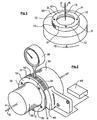
- Fig 1 shows a rotary encoder scale member 10 mounted to a rotary table 20 which rotates in the direction of arrow Z about axis P.
- Marks 15 are formed on the encoder scale member 10 about axis P to divide the encoder into predetermined angular divisions.
- the encoder scale member will have a nominal geometric axis N which will be very close to axis P, but the two axes may not be exactly in alignment.
- This misalignment can be measured before the encoder scale member 10 is removed from the table 20 using a dial test indicator (DTI); a DTI 50 is shown in Fig 2 .
- the DTI is used to take four run-out measurements with the encoder scale member rotated to points A,B,C and D. These run-out values are recorded as calibration data.
- Fig 2 shows the encoder scale member 10 fitted to a shaft 30.
- the encoder scale member 10 and shaft 30 have complementary taper mountings (hidden) which allow some adjustment of the encoder scale member 10 when mounted to the shaft 30 by means of tightening screws 32 in the screw holes 12.
- the DTI 50 has a fixed position and can be used to determine the run-out when the encoder scale member is rotated to the positions A,B,C, and D (hidden).
- the adjustment of the screws 32 can result in the encoder being mounted reasonably well about the axis of shaft rotation Q but some run-out may remain.
- the encoder scale member will thus be rotating about axis Q which is not the same as axis P.
- the encoder reader 40 is used to read angular measurements of the shaft 30 in use.
- eccentricities can be used to compensate for angular error as outlined in the following description. Firstly, however, it should be noted the magnitude of errors in comparison to the radius of the encoder scale member 10 has been greatly exaggerated to explain the effect. In reality the eccentricity is typically a few ⁇ m. Also the form (out-of-round) errors of an encoder are greatly exaggerated.
- Fig 3 shows encoder scale member 10 mounted about axis P as it would be when graduations 15 are produced.
- the encoder scale member 10 (which may not be exactly circular) has a nominal geometric centre N, however when graduated it was rotated about axis P. This non-perfect mounting will be manifested as eccentricity and can be measured before the encoder scale member 10 is removed from its production table 20.
- four substantially equispaced positions A,B,C and D are used as measurement points, yielding four dimensions of run-out when compared with a circle F of arbitrary radius p centred at P.
- the positions A,B,C and D each have respective radii r a , r b , r c and r d from point P.
- Radius p is chosen so that a,b,c and d are all positive and small (including zero) for simplicity in this example.
- Fig 4 shows encoder 10 now mounted about axis Q as it would be when installed and ready for use.
- distance z which is small compared with the encoder's nominal radius.
- This separation has coordinates x and y and inclination ⁇ .
- Four further run-out dimensions can be determined (a',b',c' and d') at nominally the same points A,B,C and D with respect to another circle G centred at Q and again of arbitrary but convenient radius q.
- Fig 5 shows a partial enlarged view of Fig 4 with the relevant dimensions more clearly shown.
- ⁇ ⁇
- An encoder is to be mounted to a shaft and its error due to eccentricity is to be determined.
- One known approach to determine angular error would be to compare the installed angular measurements with a master reference and to devise an error map. Such a technique requires an expensive reference and careful mounting of the reference relative to the installed centre of rotation.
- eccentricity error determination and adjustment may be used.
- Another technique is used to predict and compensate for errors caused by eccentricity, knowing the as manufactured eccentricity errors.
- Fig 4 shows, with x ⁇ 0 and y>0 that P is in the "top left quadrant" with respect to Q. Hence the angle between the line of centres QP, and the datum direction on the encoder to point A is ⁇ ⁇ 151°.
- the error ⁇ is shown in Fig 8a .
- the correction to be applied at any angle relative to datum A is shown in Fig 8b . Consequently the encoder error as installed, including eccentricity errors for manufacturing, expressed as the excess of indicated angle ⁇ over true angle ⁇ of head rotation clockwise from line of centres at H' on the fixed encoder is ⁇ ⁇ 14 arc" sin ⁇ .
- This predicted error can then be used to create an error map or similar means of correction to the apparent angle, without any need to calibrate against a master angular reference.
- Such an error map is shown in Fig 8a with respect to line of centres H' and Fig 8b , more conveniently from point A on the encoder.
- an error ⁇ and phase ⁇ can be obtained using an algorithm.
- Such an error signal can be used to correct the apparent angular signal obtained from the reader 40. This can be achieved by signal processing means 60.
- the signal processor can automatically add or subtract an angular value in a manner similar to the correction obtainable from the graphs of Figs 7 and 8 , dependent on the position of the encoder relative to a datum.
- the encoder shown need not have its markings aligned in an axial manner.
- the markings could be radial, with some surface or markings available from which eccentricity can be determined.
- the encoder could be arcuate rather than completely circular.
- Angular incremental marks on an encoder are illustrated, but absolute encoders might be used also with equal effect, whereby absolute angular measurement would be corrected.
- the encoder shown is of an optical type however other encoders can be used e.g. magnetic, capacitive etc.
- the calibration data obtained when the eccentricity is measured following manufacture of the encoder can be assumed to be zero.
- this technique will provide less accuracy if the marks on the encoder are not accurately divided about the geometric centre of the encoder during manufacture.
- a DTI need not be used for measurement of the eccentricity of the encoder. Other displacement measurement devices could be used.
- Adjustment of the encoder about a nominal centre could be other than the taper mount discussed e.g. radial adjustment screws could be employed.
- the eccentricity error can be mapped, and possibly together with errors from other sources, recorded in an error map rather than continual calculation.
Landscapes
- Physics & Mathematics (AREA)
- General Physics & Mathematics (AREA)
- Transmission And Conversion Of Sensor Element Output (AREA)
- Optical Transform (AREA)
Claims (17)
- Verfahren zum Erzeugen eines Drehcodiererskalenelements, mit den Schritten:(i) Nehmen eines Codiererskalenrohlings, der ein geometrisches Zentrum aufweist,(ii) Montieren des Codiererskalenrohlings zentriert um ein zweites Zentrum,(iii) Messen einer Exzentrizität zwischen dem geometrischen Zentrum und dem zweiten Zentrum durch Messen und Aufzeichnen von Werten der Änderung eines scheinbaren Radius eines Elements des Codiererskalenelements, wenn das Codiererskalenelement zu einer Mehrzahl verschiedener Winkelorientierungen gedreht wird, dadurch gekennzeichnet, dass das Verfahren den Schritt umfasst:(iv) Erzeugen einer Skala an dem Codiererskalenrohling, wodurch ein Codiererskalenelement gebildet wird, wobei die Skala des Codiererskalenelements um das zweite Zentrum zentriert ist.
- Verfahren nach Anspruch 1,
wobei die Mehrzahl verschiedener Winkelorientierungen drei oder mehr verschiedene Winkelorientierungen umfasst. - Verfahren nach einem der Ansprüche 1 bis 2,
wobei das Codiererskalenelement zumindest eine Markierung umfasst, um die Mehrzahl von Orientierungen festzustellen. - Verfahren zum Erzeugen eines Drehcodierers, mit dem Verfahren zum Erzeugen eines Drehcodiererskalenelements nach einem der vorhergehenden Ansprüche und ferner mit dem Schritt (v) zum Anbringen des Codiererskalenelements an einem Arbeitsort zentriert um ein drittes Zentrum.
- Verfahren nach Anspruch 4,
mit dem Schritt (vi) zum Messen der Exzentrizität zwischen dem geometrischen Zentrum und dem dritten Zentrum. - Verfahren nach Anspruch 5,
wobei der Schritt (vi) ein Messen der Änderung des scheinbaren Radius eines Elements des Codiererskalenelements an einer Mehrzahl von Winkelorientierungen umfasst. - Verfahren nach Anspruch 6,
wobei der Schritt (vi) ein Messen der Änderung des scheinbaren Radius eines Elementes des Codiererskalenelements an drei oder mehr Winkelorientierungen umfasst. - Verfahren nach Anspruch 7,
wobei Schritt (iii) ein Messen der Änderung des scheinbaren Radius bei denselben Winkelorientierungen, die bei Schritt (vi) gemessen sind, umfasst. - Verfahren nach einem der Ansprüche 5 bis 8,
mit dem Schritt (vii) zum Einstellen des Arbeitsorts des Codiererskalenelements. - Verfahren nach Anspruch 9,
wobei der Schritt (vii) ein Einstellen des Arbeitsorts des Codiererskalenelements und ein Wiederholen von Schritt (vi) umfasst, bis die Exzentrizität zwischen dem geometrischen Zentrum und dem zweiten Zentrum, wie bei Schritt (vi) gemessen ist, im Wesentlichen mit der Exzentrizität zwischen dem geometrischen Zentrum und dem dritten Zentrum, wie bei Schritt (iii) gemessen ist, zusammenpasst. - Verfahren nach einem der Ansprüche 6 bis 10,
mit dem Schritt (viii) zum Berechnen der Amplitude und Phase des sinusförmigen Exzentrizitätsfehlers, der durch die Differenz der Position des zweiten und dritten Zentrums bewirkt wird. - Verfahren nach Anspruch 11,
mit dem Schritt (ix) zum Erzeugen eines Winkelausgangssignals, das in Bezug auf Exzentrizität korrigiert ist. - Verfahren nach einem der vorhergehenden Ansprüche,
wobei der Schritt (iv) die Verwendung eines Lasers umfasst, um Skalenmarkierungen an dem Codiererskalenrohling zu bilden. - Verfahren nach einem der vorhergehenden Ansprüche,
wobei das Codiererskalenelement einen Ring und/oder ein bogenförmiges Element umfasst. - Verfahren zum Montieren eines Codiererskalenelements, wobei das Verfahren durch die Schritte gekennzeichnet ist aus:(a) Nehmen eines Codiererskalenelements, das ein geometrisches Zentrum aufweist, wobei das Codiererskalenelement auch eine Skala umfasst, die um ein zweites Zentrum zentriert ist, wobei die Exzentrizität zwischen dem geometrischen Zentrum und dem zweiten Zentrum bekannt ist, wobei Schritt (a) das Nehmen einen Codiererskalenelements umfasst, das unter Verwendung eines Verfahrens nach einem der Ansprüche 1 bis 3 geformt ist,(b) Montieren des Codiererskalenelements an einem Arbeitsort zentriert um ein drittes Zentrum, und(c) Messen der Exzentrizität zwischen dem geometrischen Zentrum und dem dritten Zentrum.
- Verfahren nach Anspruch 15,
ferner mit dem Schritt (d) zum Einstellen des Arbeitsorts und Wiederholen des Schritts (c), bis die Exzentrizität zwischen dem geometrischen Zentrum und dem dritten Zentrum im Wesentlichen mit der bekannten Exzentrizität zwischen dem geometrischen Zentrum und dem zweiten Zentrum zusammenpasst. - Verfahren nach einem der vorhergehenden Ansprüche 15 bis 16, mit dem Schritt (e) zum Berechnen der Amplitude und der Phase des sinusförmigen Exzentrizitätsfehlers, der durch die Differenz der Position des zweiten und dritten Zentrums bewirkt ist.
Applications Claiming Priority (2)
| Application Number | Priority Date | Filing Date | Title |
|---|---|---|---|
| GBGB0508325.8A GB0508325D0 (en) | 2005-04-26 | 2005-04-26 | Rotary encoders |
| PCT/GB2006/001500 WO2006114602A1 (en) | 2005-04-26 | 2006-04-25 | Method of producing a rotary encoder scale member |
Publications (3)
| Publication Number | Publication Date |
|---|---|
| EP1877735A1 EP1877735A1 (de) | 2008-01-16 |
| EP1877735B1 EP1877735B1 (de) | 2013-01-16 |
| EP1877735B2 true EP1877735B2 (de) | 2019-09-25 |
Family
ID=34640073
Family Applications (1)
| Application Number | Title | Priority Date | Filing Date |
|---|---|---|---|
| EP06726889.6A Expired - Lifetime EP1877735B2 (de) | 2005-04-26 | 2006-04-25 | Verfahren zum herstellen eines drehgeber-skalenglieds |
Country Status (6)
| Country | Link |
|---|---|
| US (1) | US7958620B2 (de) |
| EP (1) | EP1877735B2 (de) |
| JP (1) | JP4914436B2 (de) |
| CN (1) | CN100585336C (de) |
| GB (1) | GB0508325D0 (de) |
| WO (1) | WO2006114602A1 (de) |
Families Citing this family (21)
| Publication number | Priority date | Publication date | Assignee | Title |
|---|---|---|---|---|
| US7912572B2 (en) * | 2007-09-20 | 2011-03-22 | General Electric Company | Calibration assembly for an inspection system |
| CN102132126B (zh) * | 2008-08-26 | 2015-04-08 | 株式会社尼康 | 编码器系统、信号处理方法 |
| DE112011104863B4 (de) * | 2011-02-09 | 2019-06-13 | Mitsubishi Electric Corporation | Drehgeber |
| JP5798824B2 (ja) * | 2011-07-22 | 2015-10-21 | 株式会社ミツトヨ | 目盛誤差算出装置、目盛誤差校正装置、及び目盛誤差算出方法 |
| JP6003372B2 (ja) | 2012-08-07 | 2016-10-05 | 富士通株式会社 | 光学式ロータリーエンコーダ及びその補正方法 |
| JP6147038B2 (ja) * | 2013-03-15 | 2017-06-14 | キヤノン株式会社 | 位置検出装置、レンズ装置、撮像システム、および、工作装置 |
| CN105229424B (zh) * | 2013-05-21 | 2017-05-24 | 三菱电机株式会社 | 用于自校准旋转编码器的方法 |
| US10119842B1 (en) * | 2014-08-05 | 2018-11-06 | X Development Llc | Encoder design and use |
| JP2018059714A (ja) | 2016-09-30 | 2018-04-12 | キヤノン株式会社 | 偏芯算出方法、ロータリエンコーダ、ロボットアーム及びロボット装置 |
| JP6845517B2 (ja) * | 2017-08-22 | 2021-03-17 | 国立研究開発法人産業技術総合研究所 | エンコーダ |
| FR3086751B1 (fr) * | 2018-09-27 | 2020-10-09 | Valeo Embrayages | Procede de calibrage d'un dispositif rotatif equipe d'une cible |
| CN109357691B (zh) * | 2018-11-27 | 2023-11-21 | 重庆机床(集团)有限责任公司 | 移动式带锥柄双斜面调整的编码器接口 |
| JP2021071444A (ja) * | 2019-11-01 | 2021-05-06 | 株式会社東海理化電機製作所 | 回転角検出装置 |
| CN111750910B (zh) * | 2020-07-31 | 2025-06-03 | 长春禹衡光学有限公司 | 分体式角度编码器的调制盘及其安装总成和安装方法 |
| JP2024506064A (ja) | 2021-02-09 | 2024-02-08 | レニショウ パブリック リミテッド カンパニー | ロータリーエンコーダ |
| JP2022179101A (ja) * | 2021-05-21 | 2022-12-02 | ミネベアミツミ株式会社 | アブソリュートエンコーダ、アブソリュートエンコーダの角度誤差補正装置、及び、アブソリュートエンコーダの角度誤差補正方法 |
| ES2961960T3 (es) | 2021-06-07 | 2024-03-14 | Heidenhain Gmbh Dr Johannes | Método para posicionar un cuerpo con una escala de ángulo |
| CN114034330B (zh) * | 2021-10-28 | 2024-05-31 | 超同步股份有限公司 | 一种齿轮式编码器的补偿方法及系统 |
| EP4253916A1 (de) * | 2022-04-01 | 2023-10-04 | Renishaw PLC | Verfahren zur montage eines drehbaren skalenelements |
| JP7447324B1 (ja) | 2023-02-07 | 2024-03-11 | 株式会社マグネスケール | ロータリーエンコーダ、及びロータリーエンコーダシステム、並びにロータリーエンコーダを用いた回転角度検出方法 |
| CN118882716B (zh) * | 2024-09-27 | 2025-02-18 | 科瑞工业自动化系统(苏州)有限公司 | 适应多向轴窜的编码器校准方法、系统、介质和设备 |
Family Cites Families (12)
| Publication number | Priority date | Publication date | Assignee | Title |
|---|---|---|---|---|
| US4554044A (en) * | 1984-03-07 | 1985-11-19 | Harris Graphics Corporation | Collating apparatus with adjustable gear |
| DE3742295A1 (de) * | 1987-12-14 | 1989-06-22 | Heidenhain Gmbh Dr Johannes | Positionsmesseinrichtung mit mehreren abtaststellen |
| JPH06109481A (ja) * | 1992-09-28 | 1994-04-19 | Yokogawa Electric Corp | コード板取付位置調整装置 |
| JPH0843129A (ja) * | 1994-07-28 | 1996-02-16 | Canon Inc | 変位情報記録方法 |
| JP3166496B2 (ja) | 1994-08-19 | 2001-05-14 | 富士電機株式会社 | 回転エンコーダの偏心誤差補正装置 |
| JP3430768B2 (ja) * | 1996-01-17 | 2003-07-28 | 三菱電機株式会社 | 芯ずれ調整装置及び調整方法 |
| US6304825B1 (en) * | 1999-01-19 | 2001-10-16 | Xerox Corporation | Rotary encoder error compensation system and method for photoreceptor surface motion sensing and control |
| DE10019499B4 (de) * | 2000-04-19 | 2009-05-20 | Siemens Ag | Beschriftungsverfahren für einen rotationssymmetrischen Signalträger und hiermit korrespondierende Beschriftungsvorrichtung |
| GB0127410D0 (en) | 2001-11-15 | 2002-01-09 | Renishaw Plc | Laser substrate treatment |
| DE502005008125D1 (de) * | 2004-09-29 | 2009-10-29 | Heidenhain Gmbh Dr Johannes | Verfahren zur Herstellung und Montage eines Körpers mit einer Winkelskalierung |
| JP2006292724A (ja) * | 2005-03-17 | 2006-10-26 | Ricoh Co Ltd | 回転角検出装置、回転角検出装置の製造装置、回転角検出装置の製造方法、記録媒体および画像形成装置 |
| GB0508335D0 (en) | 2005-04-26 | 2005-06-01 | Renishaw Plc | Encoder error determination |
-
2005
- 2005-04-26 GB GBGB0508325.8A patent/GB0508325D0/en not_active Ceased
-
2006
- 2006-04-25 WO PCT/GB2006/001500 patent/WO2006114602A1/en not_active Ceased
- 2006-04-25 CN CN200680013743A patent/CN100585336C/zh not_active Expired - Fee Related
- 2006-04-25 US US11/886,064 patent/US7958620B2/en active Active
- 2006-04-25 JP JP2008508286A patent/JP4914436B2/ja not_active Expired - Fee Related
- 2006-04-25 EP EP06726889.6A patent/EP1877735B2/de not_active Expired - Lifetime
Also Published As
| Publication number | Publication date |
|---|---|
| EP1877735B1 (de) | 2013-01-16 |
| GB0508325D0 (en) | 2005-06-01 |
| US20080189934A1 (en) | 2008-08-14 |
| CN100585336C (zh) | 2010-01-27 |
| WO2006114602A1 (en) | 2006-11-02 |
| JP4914436B2 (ja) | 2012-04-11 |
| CN101163947A (zh) | 2008-04-16 |
| US7958620B2 (en) | 2011-06-14 |
| EP1877735A1 (de) | 2008-01-16 |
| JP2008539407A (ja) | 2008-11-13 |
Similar Documents
| Publication | Publication Date | Title |
|---|---|---|
| EP1877735B2 (de) | Verfahren zum herstellen eines drehgeber-skalenglieds | |
| JP5676850B2 (ja) | 回転エンコーダー装置、および、方法 | |
| US7797981B2 (en) | Position measuring device | |
| EP2325612B1 (de) | Verfahren zur Kalibrierung eines Drehwinkelsensors mit einem Laser Gyroskop | |
| JP4142942B2 (ja) | ロータリエンコーダ | |
| CN101583851B (zh) | 用于确定在角度测量仪中导致偏心度的作用变量的方法 | |
| US7825367B2 (en) | Rotary encoder | |
| CN114034329B (zh) | 一种圆光栅编码器的偏心校正方法 | |
| WO2021017075A1 (zh) | 混合编码器的位置确定方法、装置、设备及可读存储介质 | |
| US5052111A (en) | Method and apparatus for providing runout compensation in a wheel | |
| US20090095892A1 (en) | Encoder Error Determination | |
| AU2005205743A1 (en) | Method and apparatuses for the exact determination of an angle of rotation | |
| CN114139106B (zh) | 一种混合型转台谐波误差函数拟合方法 | |
| JP5442174B2 (ja) | スケール読み取り装置およびその回転リング | |
| US5414516A (en) | Position measuring apparatus | |
| RU2720052C1 (ru) | Способ измерения угла поворота и устройство его реализующее | |
| JPH0410974B2 (de) | ||
| CN117990149B (zh) | 一种圆光栅z轴偏移量的检测方法 | |
| JP4528083B2 (ja) | タイヤユニフォーミティの測定方法およびそれに用いられるタイヤユニフォーミティ測定装置 | |
| JP2006105773A (ja) | タイヤユニフォーミティの測定装置およびその製造方法 | |
| JPS6110165Y2 (de) | ||
| Ren et al. | Error Analysis of Circular Gratings Angle-Measuring System | |
| JPH11125540A (ja) | 回転角度検出エンコーダ | |
| IL310401A (en) | A method for correcting errors in measuring angular position by an angular position sensor | |
| Leslie | Widening the applications of diffraction gratings for measurement and control |
Legal Events
| Date | Code | Title | Description |
|---|---|---|---|
| PUAI | Public reference made under article 153(3) epc to a published international application that has entered the european phase |
Free format text: ORIGINAL CODE: 0009012 |
|
| 17P | Request for examination filed |
Effective date: 20071120 |
|
| AK | Designated contracting states |
Kind code of ref document: A1 Designated state(s): AT BE BG CH CY CZ DE DK EE ES FI FR GB GR HU IE IS IT LI LT LU LV MC NL PL PT RO SE SI SK TR |
|
| 17Q | First examination report despatched |
Effective date: 20080306 |
|
| DAX | Request for extension of the european patent (deleted) | ||
| GRAP | Despatch of communication of intention to grant a patent |
Free format text: ORIGINAL CODE: EPIDOSNIGR1 |
|
| GRAS | Grant fee paid |
Free format text: ORIGINAL CODE: EPIDOSNIGR3 |
|
| GRAA | (expected) grant |
Free format text: ORIGINAL CODE: 0009210 |
|
| AK | Designated contracting states |
Kind code of ref document: B1 Designated state(s): AT BE BG CH CY CZ DE DK EE ES FI FR GB GR HU IE IS IT LI LT LU LV MC NL PL PT RO SE SI SK TR |
|
| REG | Reference to a national code |
Ref country code: GB Ref legal event code: FG4D |
|
| REG | Reference to a national code |
Ref country code: CH Ref legal event code: EP |
|
| REG | Reference to a national code |
Ref country code: IE Ref legal event code: FG4D |
|
| REG | Reference to a national code |
Ref country code: CH Ref legal event code: EP Ref country code: AT Ref legal event code: REF Ref document number: 594112 Country of ref document: AT Kind code of ref document: T Effective date: 20130215 |
|
| REG | Reference to a national code |
Ref country code: DE Ref legal event code: R096 Ref document number: 602006034230 Country of ref document: DE Effective date: 20130314 |
|
| REG | Reference to a national code |
Ref country code: AT Ref legal event code: MK05 Ref document number: 594112 Country of ref document: AT Kind code of ref document: T Effective date: 20130116 |
|
| REG | Reference to a national code |
Ref country code: NL Ref legal event code: VDEP Effective date: 20130116 |
|
| REG | Reference to a national code |
Ref country code: LT Ref legal event code: MG4D |
|
| PG25 | Lapsed in a contracting state [announced via postgrant information from national office to epo] |
Ref country code: IS Free format text: LAPSE BECAUSE OF FAILURE TO SUBMIT A TRANSLATION OF THE DESCRIPTION OR TO PAY THE FEE WITHIN THE PRESCRIBED TIME-LIMIT Effective date: 20130516 Ref country code: ES Free format text: LAPSE BECAUSE OF FAILURE TO SUBMIT A TRANSLATION OF THE DESCRIPTION OR TO PAY THE FEE WITHIN THE PRESCRIBED TIME-LIMIT Effective date: 20130427 Ref country code: LT Free format text: LAPSE BECAUSE OF FAILURE TO SUBMIT A TRANSLATION OF THE DESCRIPTION OR TO PAY THE FEE WITHIN THE PRESCRIBED TIME-LIMIT Effective date: 20130116 Ref country code: AT Free format text: LAPSE BECAUSE OF FAILURE TO SUBMIT A TRANSLATION OF THE DESCRIPTION OR TO PAY THE FEE WITHIN THE PRESCRIBED TIME-LIMIT Effective date: 20130116 Ref country code: BG Free format text: LAPSE BECAUSE OF FAILURE TO SUBMIT A TRANSLATION OF THE DESCRIPTION OR TO PAY THE FEE WITHIN THE PRESCRIBED TIME-LIMIT Effective date: 20130416 Ref country code: CY Free format text: LAPSE BECAUSE OF FAILURE TO SUBMIT A TRANSLATION OF THE DESCRIPTION OR TO PAY THE FEE WITHIN THE PRESCRIBED TIME-LIMIT Effective date: 20130116 Ref country code: SE Free format text: LAPSE BECAUSE OF FAILURE TO SUBMIT A TRANSLATION OF THE DESCRIPTION OR TO PAY THE FEE WITHIN THE PRESCRIBED TIME-LIMIT Effective date: 20130116 Ref country code: BE Free format text: LAPSE BECAUSE OF FAILURE TO SUBMIT A TRANSLATION OF THE DESCRIPTION OR TO PAY THE FEE WITHIN THE PRESCRIBED TIME-LIMIT Effective date: 20130116 |
|
| PG25 | Lapsed in a contracting state [announced via postgrant information from national office to epo] |
Ref country code: SI Free format text: LAPSE BECAUSE OF FAILURE TO SUBMIT A TRANSLATION OF THE DESCRIPTION OR TO PAY THE FEE WITHIN THE PRESCRIBED TIME-LIMIT Effective date: 20130116 Ref country code: GR Free format text: LAPSE BECAUSE OF FAILURE TO SUBMIT A TRANSLATION OF THE DESCRIPTION OR TO PAY THE FEE WITHIN THE PRESCRIBED TIME-LIMIT Effective date: 20130417 Ref country code: PL Free format text: LAPSE BECAUSE OF FAILURE TO SUBMIT A TRANSLATION OF THE DESCRIPTION OR TO PAY THE FEE WITHIN THE PRESCRIBED TIME-LIMIT Effective date: 20130116 Ref country code: NL Free format text: LAPSE BECAUSE OF FAILURE TO SUBMIT A TRANSLATION OF THE DESCRIPTION OR TO PAY THE FEE WITHIN THE PRESCRIBED TIME-LIMIT Effective date: 20130116 Ref country code: LV Free format text: LAPSE BECAUSE OF FAILURE TO SUBMIT A TRANSLATION OF THE DESCRIPTION OR TO PAY THE FEE WITHIN THE PRESCRIBED TIME-LIMIT Effective date: 20130116 Ref country code: PT Free format text: LAPSE BECAUSE OF FAILURE TO SUBMIT A TRANSLATION OF THE DESCRIPTION OR TO PAY THE FEE WITHIN THE PRESCRIBED TIME-LIMIT Effective date: 20130516 Ref country code: FI Free format text: LAPSE BECAUSE OF FAILURE TO SUBMIT A TRANSLATION OF THE DESCRIPTION OR TO PAY THE FEE WITHIN THE PRESCRIBED TIME-LIMIT Effective date: 20130116 |
|
| PLBI | Opposition filed |
Free format text: ORIGINAL CODE: 0009260 |
|
| PG25 | Lapsed in a contracting state [announced via postgrant information from national office to epo] |
Ref country code: DK Free format text: LAPSE BECAUSE OF FAILURE TO SUBMIT A TRANSLATION OF THE DESCRIPTION OR TO PAY THE FEE WITHIN THE PRESCRIBED TIME-LIMIT Effective date: 20130116 Ref country code: SK Free format text: LAPSE BECAUSE OF FAILURE TO SUBMIT A TRANSLATION OF THE DESCRIPTION OR TO PAY THE FEE WITHIN THE PRESCRIBED TIME-LIMIT Effective date: 20130116 Ref country code: RO Free format text: LAPSE BECAUSE OF FAILURE TO SUBMIT A TRANSLATION OF THE DESCRIPTION OR TO PAY THE FEE WITHIN THE PRESCRIBED TIME-LIMIT Effective date: 20130116 Ref country code: EE Free format text: LAPSE BECAUSE OF FAILURE TO SUBMIT A TRANSLATION OF THE DESCRIPTION OR TO PAY THE FEE WITHIN THE PRESCRIBED TIME-LIMIT Effective date: 20130116 Ref country code: CZ Free format text: LAPSE BECAUSE OF FAILURE TO SUBMIT A TRANSLATION OF THE DESCRIPTION OR TO PAY THE FEE WITHIN THE PRESCRIBED TIME-LIMIT Effective date: 20130116 |
|
| 26 | Opposition filed |
Opponent name: DR. JOHANNES HEIDENHAIN GMBH Effective date: 20131010 |
|
| PLAX | Notice of opposition and request to file observation + time limit sent |
Free format text: ORIGINAL CODE: EPIDOSNOBS2 |
|
| PG25 | Lapsed in a contracting state [announced via postgrant information from national office to epo] |
Ref country code: MC Free format text: LAPSE BECAUSE OF FAILURE TO SUBMIT A TRANSLATION OF THE DESCRIPTION OR TO PAY THE FEE WITHIN THE PRESCRIBED TIME-LIMIT Effective date: 20130116 |
|
| REG | Reference to a national code |
Ref country code: CH Ref legal event code: PL |
|
| REG | Reference to a national code |
Ref country code: DE Ref legal event code: R026 Ref document number: 602006034230 Country of ref document: DE Effective date: 20131010 |
|
| REG | Reference to a national code |
Ref country code: IE Ref legal event code: MM4A |
|
| PG25 | Lapsed in a contracting state [announced via postgrant information from national office to epo] |
Ref country code: LI Free format text: LAPSE BECAUSE OF NON-PAYMENT OF DUE FEES Effective date: 20130430 Ref country code: CH Free format text: LAPSE BECAUSE OF NON-PAYMENT OF DUE FEES Effective date: 20130430 |
|
| REG | Reference to a national code |
Ref country code: FR Ref legal event code: ST Effective date: 20131231 |
|
| PG25 | Lapsed in a contracting state [announced via postgrant information from national office to epo] |
Ref country code: FR Free format text: LAPSE BECAUSE OF NON-PAYMENT OF DUE FEES Effective date: 20130430 |
|
| PLAF | Information modified related to communication of a notice of opposition and request to file observations + time limit |
Free format text: ORIGINAL CODE: EPIDOSCOBS2 |
|
| PG25 | Lapsed in a contracting state [announced via postgrant information from national office to epo] |
Ref country code: IE Free format text: LAPSE BECAUSE OF NON-PAYMENT OF DUE FEES Effective date: 20130425 |
|
| PLBB | Reply of patent proprietor to notice(s) of opposition received |
Free format text: ORIGINAL CODE: EPIDOSNOBS3 |
|
| PG25 | Lapsed in a contracting state [announced via postgrant information from national office to epo] |
Ref country code: TR Free format text: LAPSE BECAUSE OF FAILURE TO SUBMIT A TRANSLATION OF THE DESCRIPTION OR TO PAY THE FEE WITHIN THE PRESCRIBED TIME-LIMIT Effective date: 20130116 |
|
| PG25 | Lapsed in a contracting state [announced via postgrant information from national office to epo] |
Ref country code: HU Free format text: LAPSE BECAUSE OF FAILURE TO SUBMIT A TRANSLATION OF THE DESCRIPTION OR TO PAY THE FEE WITHIN THE PRESCRIBED TIME-LIMIT; INVALID AB INITIO Effective date: 20060425 Ref country code: LU Free format text: LAPSE BECAUSE OF NON-PAYMENT OF DUE FEES Effective date: 20130425 |
|
| PGFP | Annual fee paid to national office [announced via postgrant information from national office to epo] |
Ref country code: IT Payment date: 20190419 Year of fee payment: 14 |
|
| PUAH | Patent maintained in amended form |
Free format text: ORIGINAL CODE: 0009272 |
|
| STAA | Information on the status of an ep patent application or granted ep patent |
Free format text: STATUS: PATENT MAINTAINED AS AMENDED |
|
| 27A | Patent maintained in amended form |
Effective date: 20190925 |
|
| AK | Designated contracting states |
Kind code of ref document: B2 Designated state(s): AT BE BG CH CY CZ DE DK EE ES FI FR GB GR HU IE IS IT LI LT LU LV MC NL PL PT RO SE SI SK TR |
|
| REG | Reference to a national code |
Ref country code: DE Ref legal event code: R102 Ref document number: 602006034230 Country of ref document: DE |
|
| PGFP | Annual fee paid to national office [announced via postgrant information from national office to epo] |
Ref country code: GB Payment date: 20190429 Year of fee payment: 14 |
|
| GBPC | Gb: european patent ceased through non-payment of renewal fee |
Effective date: 20200425 |
|
| PG25 | Lapsed in a contracting state [announced via postgrant information from national office to epo] |
Ref country code: GB Free format text: LAPSE BECAUSE OF NON-PAYMENT OF DUE FEES Effective date: 20200425 |
|
| PG25 | Lapsed in a contracting state [announced via postgrant information from national office to epo] |
Ref country code: IT Free format text: LAPSE BECAUSE OF NON-PAYMENT OF DUE FEES Effective date: 20200425 |
|
| PGFP | Annual fee paid to national office [announced via postgrant information from national office to epo] |
Ref country code: DE Payment date: 20220527 Year of fee payment: 17 |
|
| REG | Reference to a national code |
Ref country code: DE Ref legal event code: R119 Ref document number: 602006034230 Country of ref document: DE |
|
| PG25 | Lapsed in a contracting state [announced via postgrant information from national office to epo] |
Ref country code: DE Free format text: LAPSE BECAUSE OF NON-PAYMENT OF DUE FEES Effective date: 20231103 |