EP1877809B1 - Baugruppe zum regeln der temperatur einer integrierten schaltung - Google Patents
Baugruppe zum regeln der temperatur einer integrierten schaltung Download PDFInfo
- Publication number
- EP1877809B1 EP1877809B1 EP05824949A EP05824949A EP1877809B1 EP 1877809 B1 EP1877809 B1 EP 1877809B1 EP 05824949 A EP05824949 A EP 05824949A EP 05824949 A EP05824949 A EP 05824949A EP 1877809 B1 EP1877809 B1 EP 1877809B1
- Authority
- EP
- European Patent Office
- Prior art keywords
- spring
- carrier
- mechanical assembly
- base
- dut
- Prior art date
- Legal status (The legal status is an assumption and is not a legal conclusion. Google has not performed a legal analysis and makes no representation as to the accuracy of the status listed.)
- Expired - Lifetime
Links
Images


Classifications
-
- G—PHYSICS
- G01—MEASURING; TESTING
- G01R—MEASURING ELECTRIC VARIABLES; MEASURING MAGNETIC VARIABLES
- G01R31/00—Arrangements for testing electric properties; Arrangements for locating electric faults; Arrangements for electrical testing characterised by what is being tested not provided for elsewhere
- G01R31/28—Testing of electronic circuits, e.g. by signal tracer
- G01R31/2851—Testing of integrated circuits [IC]
- G01R31/2886—Features relating to contacting the IC under test, e.g. probe heads; chucks
- G01R31/2891—Features relating to contacting the IC under test, e.g. probe heads; chucks related to sensing or controlling of force, position, temperature
-
- H—ELECTRICITY
- H10—SEMICONDUCTOR DEVICES; ELECTRIC SOLID-STATE DEVICES NOT OTHERWISE PROVIDED FOR
- H10W—GENERIC PACKAGES, INTERCONNECTIONS, CONNECTORS OR OTHER CONSTRUCTIONAL DETAILS OF DEVICES COVERED BY CLASS H10
- H10W90/00—Package configurations
- H10W90/701—Package configurations characterised by the relative positions of pads or connectors relative to package parts
- H10W90/721—Package configurations characterised by the relative positions of pads or connectors relative to package parts of bump connectors
- H10W90/724—Package configurations characterised by the relative positions of pads or connectors relative to package parts of bump connectors between a chip and a stacked insulating package substrate, interposer or RDL
Definitions
- This invention relates to a mechanical assembly that regulates the temperature of an integrated circuit chip (IC-chip) by pressing a temperature controlled heat-exchanger against a planar surface of the IC-chip.
- IC-chip integrated circuit chip
- test signals are sent to the IC-chip while the mechanical assembly maintains the temperature of the IC-chip at a set point.
- the mechanical assembly in patent 983 includes a coil spring 20 which presses a planar surface of a liquid cooling jacket 15 against a planar surface of the IC-chip 11. Squeezing those two planar surfaces together enables heat to flow by thermal conduction from the IC-chip 11 to the liquid cooling jacket 15.
- the mechanical assembly in patent 983 includes a guidepost 18 which has one end that is rigidly attached to the cooling jacket 15, and has an opposite end that pivots on a frame 14.
- the coil spring 20 is coiled around the guidepost 18.
- the guidepost 18, together with the coil spring 20 and the cooling jacket 15, can tilt at different angles.
- FIG. 10 and 11 of U.S. patent 6,116,331 Another mechanical assembly which regulates the temperature of an IC-chip is shown in Figs. 10 and 11 of U.S. patent 6,116,331 .
- This mechanical assembly includes a single leaf spring 80 which presses a planar surface 91 of a heat-exchanger 90 against a planar surface of an IC-chip.
- the leaf spring 80 in patent '331 lies parallel to the planar surface 91 of the heat-exchanger 90, and that leaf spring must have a certain length in order to have the proper flexibility. If the leaf spring 80 is too short, it will be so stiff that the heat-exchanger 91 will press against the IC-chip with too much force and thereby damage the IC-chip.
- a primary object of the present invention is to provide an improved mechanical assembly for regulating the temperature of an IC-chip in which all of the above drawbacks with the prior art are overcome.
- the present invention is a mechanical assembly for regulating the temperature of an electronic device.
- This mechanical assembly includes a gimbal which has a base member and a carrier member that is loosely held by the base member such that the carrier member can tilt and move relative to the base member by predetermined distances.
- This mechanical assembly also includes a heat-exchanger that is attached to the carrier member and which has a face for pressing against the electronic devices.
- the mechanical assembly further includes a spring, between the base and carrier members, which is in compression and urges the carrier member away from the base member.
- the above spring has a first end with a rigid coupling to only one of the base and carrier members, and has a second end with a slideable coupling to the remaining member.
- the slideable coupling includes a plate that has -a) one face which is attached to the second end of the spring, and b) an opposite face with indentations which hold three ball bearings. These ball bearings roll on a surface of the remaining member of the gimbal.
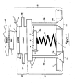
- This mechanical assembly 10 consists of a heat-exchanger 20 and a gimbal 30 which are permanently attached to each other, as shown in Fig. 1 .
- the heat-exchanger 20 includes a thin flat electric heater 21 and a conduit 22 which is permanently attached to the heater 21.
- the heater 21 has a pair of terminals 21a for passing electrical current through the heater.
- the conduit 22 has an input port 22a and an output port 22b for passing a liquid coolant through the conduit.
- Fig. 1 also shows that the gimbal 30 includes a base 31, a carrier 32, and a coiled spring 33.
- the carrier 32 is loosely held by the base 31 such that the carrier can tilt and move away from the base 31 within a predetermined range of distances.
- the carrier 31 is provided with three legs 32a, only two of which are shown. Each leg 32a extends loosely through a respective hole 31a in the base 31. Also, each leg 32a has an end 32b which is too wide to pass through its respective hole 31a.
- Fig. 1 also shows that the coiled spring 33 is interposed between the base 31 and the carrier 32.
- This coil spring 33 is in compression such that it urges the carrier 32 away from the base 31. in its quiescent state, the spring 33 presses the wide end of each leg 32a against the base 31. This centers the heat-exchanger 20 over the base 31 such that the heater 21 is at a predetermined position.
- Fig. 1 further shows that the coiled spring 33 has a first end with a fixed coupling 34 to the base 31, and a second end with a' slideable coupling 35 to the carrier 32.
- the slideable coupling 35 includes a plate 35a and three ball bearings 35b.
- One surface of the plate 35a is rigidly attached to the spring 33.
- the opposite surface of the plate 35a holds each of the ball bearings 35b in a respective indentation. All of the ball bearings 35b are pressed by the plate 35a against the carrier 32. Also, all of the ball bearings 35b roll on the carrier 32 and slip in their respective indentation in the plate 35a.
- One particular use for the above described mechanical assembly 10 is to regulate the temperature of an integrated circuit chip (IC-chip) while the IC-chip is being tested in a chip testing system.
- An IC-chip which is being tested in a chip testing system is commonly called a "DUT", which means "device under test”.
- One DUT is shown in Fig. 1 as item 41.
- This DUT 41 has input/output terminals 41a that are held by a socket 42 in the chip testing system.
- the DUT 41 can be an IC-chip by itself, and in that case the terminals 41a extend directly from the IC-chip.
- the DUT 41 can be the combination of an IC-chip plus a substrate which is attached to the IC-chip. In that case, the terminals 41a extend from the substrate.
- the DUT 41 can also include a cover which encloses the IC-chip and is attached to the substrate.
- the mechanical assembly 10 is positioned spaced-apart from the DUT 41, as shown in Fig. 1 .
- the DUT 41 and the heater 21 will ideally lie in parallel Planes.
- the DUT 41 and the heater 21 will almost always lie at an unpredictable angle with respect to each other.
- Fig. 1 shows that the DUT 41 may be tilted in the socket 42.
- Fig. 1 also shows that the DUT 41 may have a non-uniform thickness.
- the mechanical assembly 10 is moved up, or the DUT 41 is moved down, by a predetermined distance in the vertical direction.
- This vertical movement can be performed by any prior art positioning mechanism (not shown) such as a robotic arm.
- the heater 21 initially contacts one edge of the DUT 41.
- the gimbal 30 and the attached heat-exchanger 20 tilt such that the heater 21 can lie flat against the DUT 41.
- Fig. 2 shows the position of the heat-exchanger 20, the gimbal 30, and DUT 41 after the above vertical movement is complete.
- the spring 33 is compressed by a force which the positioning mechanism exerts against the base 31 in an upward direction, or against the DUT 41 in the downward direction. Consequently, the wide end 32b of each carrier leg 32a has moved away from the base 31, and that allows the carrier 32 plus the heat-exchanger 20 to tilt.
- the slideable coupling 35 on the coil spring 33 must slide relative to the carrier 32 from the initial position shown in Fig. 1 to another position shown in Fig. 2 .
- the initial position of the ball bearings 35b is labeled A, B, C
- the new position of ball bearings 35b is labeled A', B', C'.
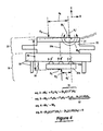
- FIG. 3 two forces F 1 and F 2 are exerted as shown on the heat-exchanger 20 and the gimbal 30, respectively. This occurs at the time instant when one edge of the DOT 41 initially contacts the heater 21. The force F 2 generates a clockwise moment M 1 about point P.
- the force F 2 is exerted by the spring 33. This force is shown as occurring in the +Y direction in alignment with the central axis 33a of the spring 33. The forces F 1 and F 2 are separated in the X direction by a distance d 2 . Consequently, the force F 2 produces the moment M 1 in the clockwise direction around the point P.
- a mathematical expression 50 for the moment M 1 is derived by equation 1 in Fig. 3 .
- k y is the spring constant in the Y direction for the spring 33.
- ⁇ Y is the amount by which the spring 33 is compressed in the Y direction from its undeformed length.
- the product (k y )( ⁇ Y) is the force F 2 which is exerted by the spring 33.
- Fig. 4 two forces F 1 ' and F 3 are exerted on the heater 21 by the DUT 41.
- the force F 1 ' occurs at the initial point of contact P.
- the force F 3 occurs at the opposite edge of the DUT 41, which is at a distance d 3 in the -X direction from point P.
- FIG. 4 two forces F 2 ' and F 4 are exerted on the slideable coupling 35 by the spring 33.
- the force F 2 ' is due to the spring 33 being compressed to a new amount ⁇ Y' in the Y direction.
- the force F 4 is due to the spring 33 being deflected by an amount ⁇ X in the X direction at the point where spring 33 connects to the slideable coupling 35.
- the deflection ⁇ X occurs as the carrier 32 and the attached heat-exchanger 20 rotate clockwise about point P.
- Equation 5 the term (k x ) ( ⁇ x) is the horizontal force F 4 which the spring 33 exerts on the plate 35a. Also in equation 5, the term (k y )( ⁇ Y') is the vertical force F 2 ' which the spring 33 exerts on the plate 35a. These forces F 4 and F 2 ' are shown in Fig. 4 .
- equation 5 cannot be met by simply making various terms in that equation larger or smaller, as desired.
- the force (k y )( ⁇ Y') cannot be made so large that damage will occur to the DUT 41.
- the distance d 2 ' cannot be made larger than one-half the width of the DUT 41.
- the distance d 4 cannot be made so small that there is no room for the heater 41, the conduit 22, and the carrier 32.
- the spring 33 becomes stiffer, which increases k x . But, with the present invention, all of these practical limitations are overcome by the slideable coupling 35 which causes ⁇ X to be small in equation 5.
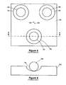
- each indentation 35c has a semi-spherical shape with a radius that is larger than the radius of the ball bearings 35b.
- One respective ball bearing 35b lies in each indentation 35c.
- the plate 35a and the ball bearings 35b are made of materials that easily slip on each other.
- the plate 35a is made of a plastic such as Teflon
- the ball bearings 35b are made of a metal such as steel.
- the indentations 35c are spaced at equal distances from each other. These indentations 35c have a geometric center 35d on the plate 35a.
- the geometric center 35d on the plate 35a will be close to, but slightly offset from, the central axis 33a of the spring 33, as shown in Fig. 5 . This offset is caused by various tolerances with which the entire mechanical assembly 10 can be manufactured.
- Fig. 9 one modification to the mechanical assembly 10 of Figs. 1-4 will be described.
- the spring 33 together with the rigid coupling 34 and the slideable coupling 35 are rotated 180°.
- the spring 33 has a fixed coupling 34 to the carrier 32 (instead of the base 31), and the spring 33 has a slideable coupling 35 to the base 31 (instead of the carrier 32).
- the DUT 41 When the modified embodiment of Fig. 9 is in a quiescent state, the DUT 41 is spaced apart from the electric heater 21. Thus, the wide ends 32b of the legs 32a are pressed against the base 31 due to the force exerted on the carrier 32 by the spring 33. Also in that quiescent state, the ball bearings 35b are at the positions A, B, C on the base 31, as labeled in Fig. 9 .
- Fig. 9 shows the position of the heat-exchanger 20, the gimbal 30, and the DUT 41 after this vertical movement is complete.
- a second modification to the mechanical assembly 10 of Figs. 1-4 will be described.
- the slideable coupling 35 of Figs. 1-4 is replaced with a solid plate 35'.
- the plate 35' has one face that is rigidly attached to the spring 33 and an opposite face that has, a small coefficient of friction such that it easily slides on the carrier 32.
- the DUT 41 When the modified embodiment of Figs. 10-11 is in a quiescent state, the DUT 41 is spaced apart from the electric heater 21. Thus, the wide ends 32b of the legs 31a are pressed against the base 31 due to the force exerted on the carrier 32 by the spring 33. Also in that quiescent state, the edges of the solid plate 35' are at the positions A and C on the base 31, as shown in Fig. 10 .
- Fig. 11 shows the position of the heat-exchanger 20, the gimbal 30, and the DUT 41 after this vertical movement is complete.
- the spring 33 together with the slideable plate 35b' and the rigid coupling 34 can be rotated 180°.
- the plate 35b' slides on the base 31, whereas the rigid coupling 34 is between the spring 33 and the carrier 32.
- the indentations 35c and respective ball bearings 35b can be increased to any desired number greater than three. This modification can be incorporated into the assembly 10 of Figs. 1-2 and/or the assembly 10 of Fig. 9 .
- the rigid coupling 34 between the spring 33 and the plate 35 in Figs. 1 , 2 , and 9 can be implemented as desired.
- the spring 33 is welded or brazed to the plate 35.
- the spring 33 is held to the plate 35 with screws or other similar fasteners.
- the spring 33 is held to the plate 35 by protrusions from the plate 35 around the spring, or an indentation in the plate 35, or simply by friction.
- the heat-exchanger 20 that is shown in the embodiments of Figs. 1 , 2 , 9 , 10 and 11 can be replaced with any other type of heat-exchanger.
- the electric heater 21 can be deleted.
- the conduit 22 gets pressed against the DUT 41, instead of the heater 21 getting pressed against the DUT 41.
- the conduit 22 can be one which passes coolant that stays in a liquid state between the input port 22a and the output port 22b, or the conduit 22 can be one which changes the coolant from a liquid state to a gas state between the input port 22a and the output port 22b.
- the spring 33 in Figs. 1 , 2 , 9 , 10 and 11 can be a cylindrical coil spring, instead of the conical coil spring that is shown.
- the spring 33 in Figs. 1 , 2 , 9 , 10 and 11 can be one which lies only in the plane of those figures.
- Such a spring in Fig. 1 could extend upward from the base 31, then loop in the plane of Fig. 1 , and then continue upward to the plate 35a.
- this loop in the plane of Fig. 1 could be replaced with a "C" shaped bend.
- a lubricant can be coated on the ball bearings 35b in Figs. 5 and 6 in order to reduce any friction which is exerted on those ball bearings.
- a lubricant can be coated on the surface of the plate 35' in Figs. 10 and 11 in order to reduce any friction which is exerted on that plate by the carrier 32.
Landscapes
- Engineering & Computer Science (AREA)
- Computer Hardware Design (AREA)
- Microelectronics & Electronic Packaging (AREA)
- General Engineering & Computer Science (AREA)
- Physics & Mathematics (AREA)
- General Physics & Mathematics (AREA)
- Testing Of Individual Semiconductor Devices (AREA)
- Coupling Device And Connection With Printed Circuit (AREA)
- Control Of Temperature (AREA)
Claims (14)
- Mechanische Baugruppe (10) zum Regeln der Temperatur einer elektronischen Vorrichtung (41), wobei die mechanische Baugruppe umfasst:eine kardanische Aufhängung (30) mit einem Unterteil (31) und einem Trägerteil (32), der vom Unterteil (31) lose gehalten ist, so dass der Trägerteil (32) gegenüber dem Unterteil (31) um vorgegebene Wege neigbar und beweglich ist;einen Wärmetauscher (20), der am Trägerteil (32) angebracht ist und eine Fläche zum Andrücken gegen die elektronische Vorrichtung (41) aufweist;wobei die kardanische Aufhängung (30) weiter eine Feder (33) zwischen dem Unterteil (31) und dem Trägerteil (32) aufweist, die den Trägerteil vom Unterteil (31) wegdrückt; unddie Feder (33) ein erstes Ende (34) mit einer starren Verbindung nur mit dem Unterteil oder mit dem Trägerteil sowie ein zweites Ende mit einer verschiebbaren Verbindung (35) mit dem anderen Teil aufweist.
- Mechanische Baugruppe (10) nach Anspruch 1, wobei die verschiebbare Verbindung (35) eine Platte (35a) umfasst, die am zweiten Ende der Feder angebracht ist und eine Oberfläche mit mindestens drei Kugellagerungen (35b) aufweist, die auf dem anderen Teil abrollen und auf der Platte (35a) gleiten.
- Mechanische Baugruppe (10) nach Anspruch 2, wobei der eine Teil mit der starren Verbindung das Unterteil (31) und der andere Teil mit der verschiebbaren Verbindung das Trägerteil (32) ist.
- Mechanische Baugruppe (10) nach Anspruch 2, wobei der eine Teil mit der starren Verbindung das Trägerteil (32) und der andere Teil mit der verschiebbaren Verbindung das Unterteil (31) ist.
- Mechanische Baugruppe (10) nach Anspruch 2, wobei die Feder (33) eine konische Schraubenfeder ist.
- Mechanische Baugruppe (10) nach Anspruch 2, wobei die Feder (33) eine zylindrische Schraubenfeder ist.
- Mechanische Baugruppe (10) nach Anspruch 2, wobei die Feder (33) in einer einzigen Ebene zwischen dem Unter- (31) und dem Trägerteil (32) liegt.
- Mechanische Baugruppe (10) nach Anspruch 2, wobei die Kugellagerungen (35b) in jeweiligen Vertiefungen in der Oberfläche der Platte (35a) angeordnet sind.
- Mechanische Baugruppe (10) nach Anspruch 1, wobei die verschiebbare Verbindung eine Platte (35a) umfasst, die am zweiten Ende der Feder (33) angebracht ist und eine Oberfläche aufweist, die auf dem anderen Teil gleitet.
- Mechanische Baugruppe (10) nach Anspruch 9, wobei der eine Teil mit der starren Verbindung das Unterteil (31) und der andere Teil mit der verschiebbaren Verbindung das Trägerteil (32) ist.
- Mechanische Baugruppe (10) nach Anspruch 9, wobei der eine Teil mit der starren Verbindung das Trägerteil (32) und der andere Teil mit der verschiebbaren Verbindung das Unterteil (31) ist.
- Mechanische Baugruppe (10) nach Anspruch 9, wobei die Feder (33) eine konische Schraubenfeder ist.
- Mechanische Baugruppe (10) nach Anspruch 9, wobei die Feder (33) eine zylindrische Schraubenfeder ist.
- Mechanische Baugruppe (10) nach Anspruch 9, wobei die Feder (33) in einer einzigen Ebene zwischen dem Unter- (31) und dem Trägerteil (32) liegt.
Applications Claiming Priority (2)
| Application Number | Priority Date | Filing Date | Title |
|---|---|---|---|
| US10/992,308 US7243704B2 (en) | 2004-11-18 | 2004-11-18 | Mechanical assembly for regulating the temperature of an electronic device, having a spring with one slideable end |
| PCT/US2005/042145 WO2006055906A2 (en) | 2004-11-18 | 2005-11-17 | Assembly for regulating the temperature of an integrated circuit |
Publications (2)
| Publication Number | Publication Date |
|---|---|
| EP1877809A2 EP1877809A2 (de) | 2008-01-16 |
| EP1877809B1 true EP1877809B1 (de) | 2008-07-23 |
Family
ID=36129901
Family Applications (1)
| Application Number | Title | Priority Date | Filing Date |
|---|---|---|---|
| EP05824949A Expired - Lifetime EP1877809B1 (de) | 2004-11-18 | 2005-11-17 | Baugruppe zum regeln der temperatur einer integrierten schaltung |
Country Status (6)
| Country | Link |
|---|---|
| US (1) | US7243704B2 (de) |
| EP (1) | EP1877809B1 (de) |
| CN (1) | CN101115999A (de) |
| AT (1) | ATE402419T1 (de) |
| DE (1) | DE602005008482D1 (de) |
| WO (1) | WO2006055906A2 (de) |
Families Citing this family (25)
| Publication number | Priority date | Publication date | Assignee | Title |
|---|---|---|---|---|
| US8464781B2 (en) | 2002-11-01 | 2013-06-18 | Cooligy Inc. | Cooling systems incorporating heat exchangers and thermoelectric layers |
| TWI300466B (en) | 2002-11-01 | 2008-09-01 | Cooligy Inc | Channeled flat plate fin heat exchange system, device and method |
| US7836597B2 (en) * | 2002-11-01 | 2010-11-23 | Cooligy Inc. | Method of fabricating high surface to volume ratio structures and their integration in microheat exchangers for liquid cooling system |
| US20040233639A1 (en) * | 2003-01-31 | 2004-11-25 | Cooligy, Inc. | Removeable heat spreader support mechanism and method of manufacturing thereof |
| US7044196B2 (en) * | 2003-01-31 | 2006-05-16 | Cooligy,Inc | Decoupled spring-loaded mounting apparatus and method of manufacturing thereof |
| US7591302B1 (en) * | 2003-07-23 | 2009-09-22 | Cooligy Inc. | Pump and fan control concepts in a cooling system |
| US7616444B2 (en) * | 2004-06-04 | 2009-11-10 | Cooligy Inc. | Gimballed attachment for multiple heat exchangers |
| US20050269691A1 (en) * | 2004-06-04 | 2005-12-08 | Cooligy, Inc. | Counter flow micro heat exchanger for optimal performance |
| US20070114010A1 (en) * | 2005-11-09 | 2007-05-24 | Girish Upadhya | Liquid cooling for backlit displays |
| US7913719B2 (en) | 2006-01-30 | 2011-03-29 | Cooligy Inc. | Tape-wrapped multilayer tubing and methods for making the same |
| US20070175621A1 (en) * | 2006-01-31 | 2007-08-02 | Cooligy, Inc. | Re-workable metallic TIM for efficient heat exchange |
| EP1987309B1 (de) * | 2006-02-16 | 2014-04-16 | Cooligy, Inc. | Flüssigkeitskühlungsschleifen für serveranwendungen |
| US8157001B2 (en) | 2006-03-30 | 2012-04-17 | Cooligy Inc. | Integrated liquid to air conduction module |
| US20070227698A1 (en) * | 2006-03-30 | 2007-10-04 | Conway Bruce R | Integrated fluid pump and radiator reservoir |
| US20070227709A1 (en) * | 2006-03-30 | 2007-10-04 | Girish Upadhya | Multi device cooling |
| US20070256815A1 (en) * | 2006-05-04 | 2007-11-08 | Cooligy, Inc. | Scalable liquid cooling system with modular radiators |
| US20080013278A1 (en) * | 2006-06-30 | 2008-01-17 | Fredric Landry | Reservoir for liquid cooling systems used to provide make-up fluid and trap gas bubbles |
| CN101261295B (zh) * | 2007-03-05 | 2010-08-25 | 海尔集团公司 | 用于lcd电视机调试生产线的自动插接工装及其控制电路 |
| CN101715536A (zh) * | 2007-05-02 | 2010-05-26 | 固利吉股份有限公司 | 用于电子冷却应用的微管/多端口逆流散热器设计 |
| TW200924625A (en) | 2007-08-07 | 2009-06-01 | Cooligy Inc | Deformable duct guides that accommodate electronic connection lines |
| CN101267013B (zh) * | 2008-04-30 | 2011-09-28 | 晶能光电(江西)有限公司 | 半导体外延片的压焊结构 |
| US9500701B2 (en) | 2010-03-17 | 2016-11-22 | Delta Design, Inc. | Alignment mechanism |
| GB2543549B (en) * | 2015-10-21 | 2020-04-15 | Andor Tech Limited | Thermoelectric Heat pump system |
| CN110879304B (zh) * | 2018-09-06 | 2022-12-30 | 致茂电子股份有限公司 | 滑移式电子元件测试装置 |
| US11378615B2 (en) | 2020-04-20 | 2022-07-05 | Aem Singapore Pte Ltd | Thermal test head for an integrated circuit device |
Family Cites Families (8)
| Publication number | Priority date | Publication date | Assignee | Title |
|---|---|---|---|---|
| US4791983A (en) * | 1987-10-13 | 1988-12-20 | Unisys Corporation | Self-aligning liquid-cooling assembly |
| US5880930A (en) * | 1997-06-18 | 1999-03-09 | Silicon Graphics, Inc. | Electromagnetic interference shielding enclosure and heat sink with compression coupling mechanism |
| US6323665B1 (en) * | 1997-10-07 | 2001-11-27 | Reliability Incorporated | Apparatus capable of high power dissipation during burn-in of a device under test |
| US6116331A (en) | 1998-12-10 | 2000-09-12 | Unisys Corporation | Mechanical assembly for regulating the temperature of an electronic device which incorporates a single leaf spring for self-alignment plus a low initial contact force and a low profile |
| US6459582B1 (en) * | 2000-07-19 | 2002-10-01 | Fujitsu Limited | Heatsink apparatus for de-coupling clamping forces on an integrated circuit package |
| US6501658B2 (en) * | 2001-02-16 | 2002-12-31 | Intel Corporation | Heatsink mounting with shock absorbers |
| US6774661B1 (en) | 2003-03-18 | 2004-08-10 | Unisys Corporation | Initial contact method of preventing an integrated circuit chip from being thermally destroyed, in a tester, due to a defective pressed joint |
| US7301773B2 (en) * | 2004-06-04 | 2007-11-27 | Cooligy Inc. | Semi-compliant joining mechanism for semiconductor cooling applications |
-
2004
- 2004-11-18 US US10/992,308 patent/US7243704B2/en not_active Expired - Fee Related
-
2005
- 2005-11-17 WO PCT/US2005/042145 patent/WO2006055906A2/en not_active Ceased
- 2005-11-17 EP EP05824949A patent/EP1877809B1/de not_active Expired - Lifetime
- 2005-11-17 DE DE602005008482T patent/DE602005008482D1/de not_active Expired - Fee Related
- 2005-11-17 AT AT05824949T patent/ATE402419T1/de not_active IP Right Cessation
- 2005-11-17 CN CNA2005800457957A patent/CN101115999A/zh active Pending
Also Published As
| Publication number | Publication date |
|---|---|
| EP1877809A2 (de) | 2008-01-16 |
| ATE402419T1 (de) | 2008-08-15 |
| WO2006055906A2 (en) | 2006-05-26 |
| CN101115999A (zh) | 2008-01-30 |
| US20060102999A1 (en) | 2006-05-18 |
| US7243704B2 (en) | 2007-07-17 |
| DE602005008482D1 (de) | 2008-09-04 |
| WO2006055906A3 (en) | 2006-09-08 |
Similar Documents
| Publication | Publication Date | Title |
|---|---|---|
| EP1877809B1 (de) | Baugruppe zum regeln der temperatur einer integrierten schaltung | |
| EP1846746B1 (de) | Testvorrichtung für mikrostösse | |
| TWI458983B (zh) | 用於與測試裝置使用之加強件以及探針卡總成 | |
| US12140625B2 (en) | Alignment mechanism | |
| US7119564B2 (en) | Method and system for compensating thermally induced motion of probe cards | |
| CN101563638B (zh) | 倾斜装置 | |
| JPH02137241A (ja) | 方向づけ調節装置 | |
| US11085949B2 (en) | Probe card assembly | |
| TW201740122A (zh) | 萬向架組件測試系統及方法 | |
| US20040042584A1 (en) | Low-cost, high precision goniometric stage for x-ray diffractography | |
| US7857295B2 (en) | Clamping mechanism | |
| JP2008262672A (ja) | マイクロトルクおよびマイクロ剛性測定装置 | |
| JP5585959B2 (ja) | マウント装置 | |
| US4157818A (en) | X-Y Movable work holder | |
| EP0276900B1 (de) | Verfahren und Vorrichtung zur Alignierung zweier Oberflächen | |
| WO2018089659A1 (en) | Probe card assembly having die-level and pin-level compliance, and associated systems and methods | |
| CN114603474B (zh) | 压力检测系统 | |
| US20070097648A1 (en) | Method and apparatus for establishing optimal thermal contact between opposing surfaces | |
| TW202043779A (zh) | 可攜式探針卡總成 | |
| JP2025049822A (ja) | 多方向入力装置 | |
| KR20060087281A (ko) | 힘조절기구를 구비한 물성 측정 장치 | |
| JPS6212951A (ja) | 磁気ヘツド支持装置 |
Legal Events
| Date | Code | Title | Description |
|---|---|---|---|
| PUAI | Public reference made under article 153(3) epc to a published international application that has entered the european phase |
Free format text: ORIGINAL CODE: 0009012 |
|
| 17P | Request for examination filed |
Effective date: 20070925 |
|
| AK | Designated contracting states |
Kind code of ref document: A2 Designated state(s): AT BE BG CH CY CZ DE DK EE ES FI FR GB GR HU IE IS IT LI LT LU LV MC NL PL PT RO SE SI SK TR |
|
| GRAP | Despatch of communication of intention to grant a patent |
Free format text: ORIGINAL CODE: EPIDOSNIGR1 |
|
| DAX | Request for extension of the european patent (deleted) | ||
| GRAS | Grant fee paid |
Free format text: ORIGINAL CODE: EPIDOSNIGR3 |
|
| GRAA | (expected) grant |
Free format text: ORIGINAL CODE: 0009210 |
|
| RIN1 | Information on inventor provided before grant (corrected) |
Inventor name: BABCOCK, JAMES, WITTMAN Inventor name: TUSTANIWSKYJ, JERRY, IHOR Inventor name: KUO, HENRY, JEN |
|
| AK | Designated contracting states |
Kind code of ref document: B1 Designated state(s): AT BE BG CH CY CZ DE DK EE ES FI FR GB GR HU IE IS IT LI LT LU LV MC NL PL PT RO SE SI SK TR |
|
| REG | Reference to a national code |
Ref country code: GB Ref legal event code: FG4D |
|
| REG | Reference to a national code |
Ref country code: CH Ref legal event code: EP |
|
| REG | Reference to a national code |
Ref country code: IE Ref legal event code: FG4D |
|
| REF | Corresponds to: |
Ref document number: 602005008482 Country of ref document: DE Date of ref document: 20080904 Kind code of ref document: P |
|
| NLV1 | Nl: lapsed or annulled due to failure to fulfill the requirements of art. 29p and 29m of the patents act | ||
| PG25 | Lapsed in a contracting state [announced via postgrant information from national office to epo] |
Ref country code: IS Free format text: LAPSE BECAUSE OF FAILURE TO SUBMIT A TRANSLATION OF THE DESCRIPTION OR TO PAY THE FEE WITHIN THE PRESCRIBED TIME-LIMIT Effective date: 20081123 Ref country code: NL Free format text: LAPSE BECAUSE OF FAILURE TO SUBMIT A TRANSLATION OF THE DESCRIPTION OR TO PAY THE FEE WITHIN THE PRESCRIBED TIME-LIMIT Effective date: 20080723 Ref country code: LT Free format text: LAPSE BECAUSE OF FAILURE TO SUBMIT A TRANSLATION OF THE DESCRIPTION OR TO PAY THE FEE WITHIN THE PRESCRIBED TIME-LIMIT Effective date: 20080723 |
|
| PGFP | Annual fee paid to national office [announced via postgrant information from national office to epo] |
Ref country code: DE Payment date: 20081121 Year of fee payment: 4 |
|
| PG25 | Lapsed in a contracting state [announced via postgrant information from national office to epo] |
Ref country code: SI Free format text: LAPSE BECAUSE OF FAILURE TO SUBMIT A TRANSLATION OF THE DESCRIPTION OR TO PAY THE FEE WITHIN THE PRESCRIBED TIME-LIMIT Effective date: 20080723 Ref country code: FI Free format text: LAPSE BECAUSE OF FAILURE TO SUBMIT A TRANSLATION OF THE DESCRIPTION OR TO PAY THE FEE WITHIN THE PRESCRIBED TIME-LIMIT Effective date: 20080723 Ref country code: LV Free format text: LAPSE BECAUSE OF FAILURE TO SUBMIT A TRANSLATION OF THE DESCRIPTION OR TO PAY THE FEE WITHIN THE PRESCRIBED TIME-LIMIT Effective date: 20080723 Ref country code: AT Free format text: LAPSE BECAUSE OF FAILURE TO SUBMIT A TRANSLATION OF THE DESCRIPTION OR TO PAY THE FEE WITHIN THE PRESCRIBED TIME-LIMIT Effective date: 20080723 Ref country code: PT Free format text: LAPSE BECAUSE OF FAILURE TO SUBMIT A TRANSLATION OF THE DESCRIPTION OR TO PAY THE FEE WITHIN THE PRESCRIBED TIME-LIMIT Effective date: 20081223 Ref country code: BG Free format text: LAPSE BECAUSE OF FAILURE TO SUBMIT A TRANSLATION OF THE DESCRIPTION OR TO PAY THE FEE WITHIN THE PRESCRIBED TIME-LIMIT Effective date: 20081023 Ref country code: ES Free format text: LAPSE BECAUSE OF FAILURE TO SUBMIT A TRANSLATION OF THE DESCRIPTION OR TO PAY THE FEE WITHIN THE PRESCRIBED TIME-LIMIT Effective date: 20081103 |
|
| PG25 | Lapsed in a contracting state [announced via postgrant information from national office to epo] |
Ref country code: BE Free format text: LAPSE BECAUSE OF FAILURE TO SUBMIT A TRANSLATION OF THE DESCRIPTION OR TO PAY THE FEE WITHIN THE PRESCRIBED TIME-LIMIT Effective date: 20080723 |
|
| PG25 | Lapsed in a contracting state [announced via postgrant information from national office to epo] |
Ref country code: EE Free format text: LAPSE BECAUSE OF FAILURE TO SUBMIT A TRANSLATION OF THE DESCRIPTION OR TO PAY THE FEE WITHIN THE PRESCRIBED TIME-LIMIT Effective date: 20080723 Ref country code: DK Free format text: LAPSE BECAUSE OF FAILURE TO SUBMIT A TRANSLATION OF THE DESCRIPTION OR TO PAY THE FEE WITHIN THE PRESCRIBED TIME-LIMIT Effective date: 20080723 |
|
| PG25 | Lapsed in a contracting state [announced via postgrant information from national office to epo] |
Ref country code: SK Free format text: LAPSE BECAUSE OF FAILURE TO SUBMIT A TRANSLATION OF THE DESCRIPTION OR TO PAY THE FEE WITHIN THE PRESCRIBED TIME-LIMIT Effective date: 20080723 Ref country code: CZ Free format text: LAPSE BECAUSE OF FAILURE TO SUBMIT A TRANSLATION OF THE DESCRIPTION OR TO PAY THE FEE WITHIN THE PRESCRIBED TIME-LIMIT Effective date: 20080723 Ref country code: RO Free format text: LAPSE BECAUSE OF FAILURE TO SUBMIT A TRANSLATION OF THE DESCRIPTION OR TO PAY THE FEE WITHIN THE PRESCRIBED TIME-LIMIT Effective date: 20080723 |
|
| PLBE | No opposition filed within time limit |
Free format text: ORIGINAL CODE: 0009261 |
|
| STAA | Information on the status of an ep patent application or granted ep patent |
Free format text: STATUS: NO OPPOSITION FILED WITHIN TIME LIMIT |
|
| PG25 | Lapsed in a contracting state [announced via postgrant information from national office to epo] |
Ref country code: MC Free format text: LAPSE BECAUSE OF NON-PAYMENT OF DUE FEES Effective date: 20081130 |
|
| 26N | No opposition filed |
Effective date: 20090424 |
|
| REG | Reference to a national code |
Ref country code: IE Ref legal event code: MM4A |
|
| PG25 | Lapsed in a contracting state [announced via postgrant information from national office to epo] |
Ref country code: IT Free format text: LAPSE BECAUSE OF FAILURE TO SUBMIT A TRANSLATION OF THE DESCRIPTION OR TO PAY THE FEE WITHIN THE PRESCRIBED TIME-LIMIT Effective date: 20080723 |
|
| REG | Reference to a national code |
Ref country code: FR Ref legal event code: ST Effective date: 20090731 |
|
| PG25 | Lapsed in a contracting state [announced via postgrant information from national office to epo] |
Ref country code: IE Free format text: LAPSE BECAUSE OF NON-PAYMENT OF DUE FEES Effective date: 20081117 |
|
| PG25 | Lapsed in a contracting state [announced via postgrant information from national office to epo] |
Ref country code: SE Free format text: LAPSE BECAUSE OF FAILURE TO SUBMIT A TRANSLATION OF THE DESCRIPTION OR TO PAY THE FEE WITHIN THE PRESCRIBED TIME-LIMIT Effective date: 20081023 |
|
| PG25 | Lapsed in a contracting state [announced via postgrant information from national office to epo] |
Ref country code: PL Free format text: LAPSE BECAUSE OF FAILURE TO SUBMIT A TRANSLATION OF THE DESCRIPTION OR TO PAY THE FEE WITHIN THE PRESCRIBED TIME-LIMIT Effective date: 20080723 |
|
| REG | Reference to a national code |
Ref country code: CH Ref legal event code: PL |
|
| GBPC | Gb: european patent ceased through non-payment of renewal fee |
Effective date: 20091117 |
|
| PG25 | Lapsed in a contracting state [announced via postgrant information from national office to epo] |
Ref country code: HU Free format text: LAPSE BECAUSE OF FAILURE TO SUBMIT A TRANSLATION OF THE DESCRIPTION OR TO PAY THE FEE WITHIN THE PRESCRIBED TIME-LIMIT Effective date: 20090124 Ref country code: LU Free format text: LAPSE BECAUSE OF NON-PAYMENT OF DUE FEES Effective date: 20081117 Ref country code: CY Free format text: LAPSE BECAUSE OF FAILURE TO SUBMIT A TRANSLATION OF THE DESCRIPTION OR TO PAY THE FEE WITHIN THE PRESCRIBED TIME-LIMIT Effective date: 20080723 |
|
| PG25 | Lapsed in a contracting state [announced via postgrant information from national office to epo] |
Ref country code: TR Free format text: LAPSE BECAUSE OF FAILURE TO SUBMIT A TRANSLATION OF THE DESCRIPTION OR TO PAY THE FEE WITHIN THE PRESCRIBED TIME-LIMIT Effective date: 20080723 |
|
| PG25 | Lapsed in a contracting state [announced via postgrant information from national office to epo] |
Ref country code: LI Free format text: LAPSE BECAUSE OF NON-PAYMENT OF DUE FEES Effective date: 20091130 Ref country code: GR Free format text: LAPSE BECAUSE OF FAILURE TO SUBMIT A TRANSLATION OF THE DESCRIPTION OR TO PAY THE FEE WITHIN THE PRESCRIBED TIME-LIMIT Effective date: 20081024 Ref country code: CH Free format text: LAPSE BECAUSE OF NON-PAYMENT OF DUE FEES Effective date: 20091130 |
|
| PG25 | Lapsed in a contracting state [announced via postgrant information from national office to epo] |
Ref country code: DE Free format text: LAPSE BECAUSE OF NON-PAYMENT OF DUE FEES Effective date: 20100601 |
|
| PG25 | Lapsed in a contracting state [announced via postgrant information from national office to epo] |
Ref country code: GB Free format text: LAPSE BECAUSE OF NON-PAYMENT OF DUE FEES Effective date: 20091117 |
|
| PG25 | Lapsed in a contracting state [announced via postgrant information from national office to epo] |
Ref country code: FR Free format text: LAPSE BECAUSE OF NON-PAYMENT OF DUE FEES Effective date: 20081130 |