EP1878859A2 - Elément de liaison pour traverses et piquets de clôtures - Google Patents
Elément de liaison pour traverses et piquets de clôtures Download PDFInfo
- Publication number
- EP1878859A2 EP1878859A2 EP07109492A EP07109492A EP1878859A2 EP 1878859 A2 EP1878859 A2 EP 1878859A2 EP 07109492 A EP07109492 A EP 07109492A EP 07109492 A EP07109492 A EP 07109492A EP 1878859 A2 EP1878859 A2 EP 1878859A2
- Authority
- EP
- European Patent Office
- Prior art keywords
- flange
- transverse
- connecting element
- axis
- fence
- Prior art date
- Legal status (The legal status is an assumption and is not a legal conclusion. Google has not performed a legal analysis and makes no representation as to the accuracy of the status listed.)
- Withdrawn
Links
- 230000007704 transition Effects 0.000 claims abstract description 12
- 239000002023 wood Substances 0.000 description 3
- 238000004519 manufacturing process Methods 0.000 description 2
- 230000001419 dependent effect Effects 0.000 description 1
- 230000014509 gene expression Effects 0.000 description 1
- 239000000463 material Substances 0.000 description 1
- 230000004048 modification Effects 0.000 description 1
- 238000012986 modification Methods 0.000 description 1
Images


Classifications
-
- E—FIXED CONSTRUCTIONS
- E04—BUILDING
- E04H—BUILDINGS OR LIKE STRUCTURES FOR PARTICULAR PURPOSES; SWIMMING OR SPLASH BATHS OR POOLS; MASTS; FENCING; TENTS OR CANOPIES, IN GENERAL
- E04H17/00—Fencing, e.g. fences, enclosures, corrals
- E04H17/14—Fences constructed of rigid elements, e.g. with additional wire fillings or with posts
- E04H17/1413—Post-and-rail fences, e.g. without vertical cross-members
- E04H17/1447—Details of connections between rails and posts
-
- E—FIXED CONSTRUCTIONS
- E04—BUILDING
- E04H—BUILDINGS OR LIKE STRUCTURES FOR PARTICULAR PURPOSES; SWIMMING OR SPLASH BATHS OR POOLS; MASTS; FENCING; TENTS OR CANOPIES, IN GENERAL
- E04H17/00—Fencing, e.g. fences, enclosures, corrals
- E04H17/14—Fences constructed of rigid elements, e.g. with additional wire fillings or with posts
- E04H17/1413—Post-and-rail fences, e.g. without vertical cross-members
- E04H17/1417—Post-and-rail fences, e.g. without vertical cross-members with vertical cross-members
-
- E—FIXED CONSTRUCTIONS
- E04—BUILDING
- E04H—BUILDINGS OR LIKE STRUCTURES FOR PARTICULAR PURPOSES; SWIMMING OR SPLASH BATHS OR POOLS; MASTS; FENCING; TENTS OR CANOPIES, IN GENERAL
- E04H17/00—Fencing, e.g. fences, enclosures, corrals
- E04H17/14—Fences constructed of rigid elements, e.g. with additional wire fillings or with posts
- E04H17/1413—Post-and-rail fences, e.g. without vertical cross-members
- E04H17/1447—Details of connections between rails and posts
- E04H17/146—Details of connections between rails and posts the rails being attached to the front faces of the posts
-
- E—FIXED CONSTRUCTIONS
- E04—BUILDING
- E04H—BUILDINGS OR LIKE STRUCTURES FOR PARTICULAR PURPOSES; SWIMMING OR SPLASH BATHS OR POOLS; MASTS; FENCING; TENTS OR CANOPIES, IN GENERAL
- E04H17/00—Fencing, e.g. fences, enclosures, corrals
- E04H17/14—Fences constructed of rigid elements, e.g. with additional wire fillings or with posts
- E04H17/1413—Post-and-rail fences, e.g. without vertical cross-members
- E04H17/1447—Details of connections between rails and posts
- E04H17/1473—Details of connections between rails and posts using fixing devices encircling, partially or fully, the post
-
- F—MECHANICAL ENGINEERING; LIGHTING; HEATING; WEAPONS; BLASTING
- F16—ENGINEERING ELEMENTS AND UNITS; GENERAL MEASURES FOR PRODUCING AND MAINTAINING EFFECTIVE FUNCTIONING OF MACHINES OR INSTALLATIONS; THERMAL INSULATION IN GENERAL
- F16B—DEVICES FOR FASTENING OR SECURING CONSTRUCTIONAL ELEMENTS OR MACHINE PARTS TOGETHER, e.g. NAILS, BOLTS, CIRCLIPS, CLAMPS, CLIPS OR WEDGES; JOINTS OR JOINTING
- F16B7/00—Connections of rods or tubes, e.g. of non-circular section, mutually, including resilient connections
- F16B7/18—Connections of rods or tubes, e.g. of non-circular section, mutually, including resilient connections using screw-thread elements
Definitions
- the invention relates to a connecting element for connecting struts extending essentially perpendicular to one another, in particular of a fence post with a fence bolt extending transversely thereto.
- a round fence bolt (not shown) horizontally extending along the transverse axis Q is laid in the shells of the transverse flanges QF1, QF2 and fastened using associated screw holes 1.
- two fence bolts can be placed end-to-end in one of the transverse flanges QF1 or QF2 and fastened thereto.
- the object of the invention was to provide fasteners of the type mentioned, which have a wider range of applications with respect to the manufacturable Zaungeometrien and / or the usable struts.
- the described connecting element with only one transverse flange has the advantage that it can be used in end or corner regions of a fence, since only one bolt or bolt end has to be fastened to the transverse flange. If two such fasteners are used, then two latches can be attached to a fence post in a wide range of different angles.
- the special design of the high flange described in c) also makes it possible in particular to realize very large, obtuse angles at which the high flanges of the two connecting elements come very close or touch each other.
- one of the transverse flanges can also be flat so that struts with a flat surface such as squared timbers or semicircular woods can be attached thereto (a "semicircular wood” being defined to have a semicircular cross-section).
- the connecting element described above combines a cylindrically curved high flange with two flat transverse flanges and thus makes it possible, for example, to attach semi-round timbers or square timbers to round fence posts.
- a fence structure can be realized, which at the same time achieves a higher stability (due to the lower tilting moment of half-round woods) with lower material consumption.
- the connecting element comes to lie in the mounted state between the connected struts.
- the distance between the connected struts is therefore always an optimum determined by the dimensions of the connecting element and is not dependent on the diameter or shape (eg round or semicircular) of the strut attached to the high flange.
- one or at least one of the two transverse flanges can be rounded at its side not connected to a transition leg.
- Such a rounding can be provided in particular when the transverse flange is flat, since in this case a strut with a flat surface (squared timber or semi-circular wood) can be fastened at different angles to the transverse flange.
- the circular outline of the transverse flange then prevents corners of the flange from protruding beyond the attached strut at certain angular positions.
- transverse flanges or high flanges of the connecting elements described preferably each contain at least one screw hole, so that the corresponding flange can be screwed or nailed to a strut.
- FIG. 1 shows a connecting element 10 known from the prior art with two transverse flanges QF1 and QF2, which are cylindrically curved about a transverse axis Q, between which a cylindrical one around a High axis H arched high flange HF is arranged, wherein the transverse axis Q and the vertical axis H are substantially perpendicular to each other. Furthermore, the transverse flanges QF1 and QF2 and the high flange HF lie in mutually offset planes (or more precisely in mutually offset layers). Screw holes 1, 2 or nail holes 3 in the transverse flanges and the high flange can be used to attach the flanges to corresponding roundwoods.
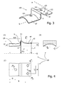
- FIGS. 3 and 4 show a first connecting element 100 according to the invention, wherein identical reference numerals or only differing by the value 100 are intended to denote similar components in all figures.
- the connecting element 100 consists of a cylindrical flange QF curved cylindrically around a transverse axis Q with a screw hole 101 which is fastened to an edge of a transition bar U perpendicular to it.
- a transition bar U perpendicular to it.
- the design of the high flange HF is asymmetrical in the sense that the distance D of its edge K1 connected to the transition web U from the transverse axis Q is greater than the distance d of the opposite free edge K2 the transverse axis Q.
- FIG. 2 shows in this respect a plan view of a fence corner, which is produced using two connecting elements 100 according to FIGS. 3 and 4.
- the Hochflansche HF of these fasteners are here attached to a high strut HS (fence post), while the associated transverse flanges QF are attached to a first and second transverse strut QS1 and QS2 (fence latch). Due to the asymmetrical design of the high flanges while the realization of very obtuse angles is possible, with the largest adjustable angle is given by the abutting of the two high flanges HF.
- a miter cut is also attached to the transverse struts QS1 or QS2 can be, if already attached to the strut, the connecting element 100, since the associated high flange HF a saw blade is not in the way.
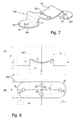
- FIGS. 5 and 6 show a connecting element 200, which represents a modification of the connecting element 100 of FIGS. 3 and 4.
- the connecting element 200 has the transverse flange QF flat, so that it can be fastened to a flat surface, for example, of a squared timber or a semi-circular wood.
- the not connected to the transition bar U edge 204 of the transverse flange QF (semi) is circular. This makes it possible to attach cross struts at different angles on the transverse flange, without the corners of the transverse flange would survive.
- FIG. 7 and 8 another connecting element 300 is shown, which has two transverse flanges QF1 and QF2 corresponding to the connecting element 10 of Figure 1, but these are flat and in plan (semi-) formed round. Therefore, the fastener 300 can be attached to flat surfaces (e.g., squared timbers, semi-roundwoods), and the associated struts can be advantageously mounted at different angles.
- flat surfaces e.g., squared timbers, semi-roundwoods
Landscapes
- Engineering & Computer Science (AREA)
- Architecture (AREA)
- Civil Engineering (AREA)
- Structural Engineering (AREA)
- Fencing (AREA)
Applications Claiming Priority (1)
| Application Number | Priority Date | Filing Date | Title |
|---|---|---|---|
| DE202006010895U DE202006010895U1 (de) | 2006-07-13 | 2006-07-13 | Verbindungselement für Zaunriegel und Zaunpfosten |
Publications (1)
| Publication Number | Publication Date |
|---|---|
| EP1878859A2 true EP1878859A2 (fr) | 2008-01-16 |
Family
ID=37440390
Family Applications (1)
| Application Number | Title | Priority Date | Filing Date |
|---|---|---|---|
| EP07109492A Withdrawn EP1878859A2 (fr) | 2006-07-13 | 2007-06-04 | Elément de liaison pour traverses et piquets de clôtures |
Country Status (2)
| Country | Link |
|---|---|
| EP (1) | EP1878859A2 (fr) |
| DE (1) | DE202006010895U1 (fr) |
Cited By (1)
| Publication number | Priority date | Publication date | Assignee | Title |
|---|---|---|---|---|
| US10214939B2 (en) | 2013-09-18 | 2019-02-26 | Jose Guadalupe GARZA MONTEMAYOR | Fence structure |
Families Citing this family (2)
| Publication number | Priority date | Publication date | Assignee | Title |
|---|---|---|---|---|
| DE102011110848B4 (de) * | 2011-08-23 | 2019-04-04 | Brühl Safety GmbH | Anschluss eines Sicherheitszaunfeldes und Sicherheitseinzäunung mit einem solchen Anschluss |
| DE202020102331U1 (de) | 2020-04-27 | 2020-05-15 | Guido Hammesfahr | Lattenhalter und Zaun mit derartigen Lattenhaltern |
-
2006
- 2006-07-13 DE DE202006010895U patent/DE202006010895U1/de not_active Expired - Lifetime
-
2007
- 2007-06-04 EP EP07109492A patent/EP1878859A2/fr not_active Withdrawn
Cited By (1)
| Publication number | Priority date | Publication date | Assignee | Title |
|---|---|---|---|---|
| US10214939B2 (en) | 2013-09-18 | 2019-02-26 | Jose Guadalupe GARZA MONTEMAYOR | Fence structure |
Also Published As
| Publication number | Publication date |
|---|---|
| DE202006010895U1 (de) | 2006-11-09 |
Similar Documents
| Publication | Publication Date | Title |
|---|---|---|
| DE2525791C3 (de) | Anordnung zum Verbinden zweier aufeinander stoßender platten- oder stangenförmiger Elemente | |
| EP2698488A2 (fr) | Système de liasion de support | |
| AT509484B1 (de) | Haltevorrichtung zum verbinden von profilen zu einem flächigen wandelement | |
| DE1936903A1 (de) | Verbindung fuer glasfaserverstaerkte Kunststoffteile od.dgl. | |
| EP1878859A2 (fr) | Elément de liaison pour traverses et piquets de clôtures | |
| EP2090704B1 (fr) | Dispositif d'ancrage | |
| EP1699986B1 (fr) | Construction de parois en bois, du type a madriers en blocs | |
| EP2126241B1 (fr) | Poutre en bois | |
| DE3839369A1 (de) | Verbindungselement und verfahren zum verbinden von voll- oder leimholzbalken in gleicher ebene | |
| EP1409811B1 (fr) | Dispositif de fixation pour elements planiformes | |
| DE2825563A1 (de) | Bauholz | |
| EP2602398B1 (fr) | Cadre en bois | |
| EP1744066B1 (fr) | Cadre aussi bien que des tiges pour un cadre | |
| AT511317B1 (de) | Balken aus holz mit schräg gestellten schrauben | |
| DE20119280U1 (de) | Brettstapelelement mit zug- und druckfesten Verbindungselementen | |
| EP0704011A1 (fr) | Systeme et element de liaison de pieces en bois | |
| DE3689994T2 (de) | Lamelliertes bauelement. | |
| DE202023106463U1 (de) | Verbindungssystem zum Verbinden einer Mehrzahl von Profilleisten und Zentralelement zur Verwendung mit einem Verbindungssystem zum Verbinden einer Mehrzahl von Profilleisten | |
| AT16045U1 (de) | Flächiger Verbund aus Holzelementen | |
| DE2707547A1 (de) | Bauteil zum herstellen eines im bauwesen zu verwendenden mehrzweckgeraetes | |
| EP3263788A1 (fr) | Liaison de deux poutres en bois | |
| DE29816981U1 (de) | An einer Stirnseite eines Holzträgers befestigter Stützfuß | |
| DE3821624C2 (de) | Plattenförmiges Bauelement | |
| DE102020132611A1 (de) | Holzbalkenverbindung und Dachtragwerk einer Leichtbauhalle mit einer derartigen Holzbalkenverbindung | |
| DE102020002251A1 (de) | Verbindungselement für den Anschluss zweier Holzbauteile |
Legal Events
| Date | Code | Title | Description |
|---|---|---|---|
| PUAI | Public reference made under article 153(3) epc to a published international application that has entered the european phase |
Free format text: ORIGINAL CODE: 0009012 |
|
| AK | Designated contracting states |
Kind code of ref document: A2 Designated state(s): AT BE BG CH CY CZ DE DK EE ES FI FR GB GR HU IE IS IT LI LT LU LV MC MT NL PL PT RO SE SI SK TR |
|
| AX | Request for extension of the european patent |
Extension state: AL BA HR MK YU |
|
| STAA | Information on the status of an ep patent application or granted ep patent |
Free format text: STATUS: THE APPLICATION HAS BEEN WITHDRAWN |
|
| 18W | Application withdrawn |
Effective date: 20100203 |