EP1878873A2 - Alliages de moteurs à turbines et orientations cristallines - Google Patents
Alliages de moteurs à turbines et orientations cristallines Download PDFInfo
- Publication number
- EP1878873A2 EP1878873A2 EP07252722A EP07252722A EP1878873A2 EP 1878873 A2 EP1878873 A2 EP 1878873A2 EP 07252722 A EP07252722 A EP 07252722A EP 07252722 A EP07252722 A EP 07252722A EP 1878873 A2 EP1878873 A2 EP 1878873A2
- Authority
- EP
- European Patent Office
- Prior art keywords
- seal
- component
- damper
- slot
- poisson
- Prior art date
- Legal status (The legal status is an assumption and is not a legal conclusion. Google has not performed a legal analysis and makes no representation as to the accuracy of the status listed.)
- Granted
Links
Images






Classifications
-
- F—MECHANICAL ENGINEERING; LIGHTING; HEATING; WEAPONS; BLASTING
- F01—MACHINES OR ENGINES IN GENERAL; ENGINE PLANTS IN GENERAL; STEAM ENGINES
- F01D—NON-POSITIVE DISPLACEMENT MACHINES OR ENGINES, e.g. STEAM TURBINES
- F01D11/00—Preventing or minimising internal leakage of working-fluid, e.g. between stages
- F01D11/005—Sealing means between non relatively rotating elements
-
- F—MECHANICAL ENGINEERING; LIGHTING; HEATING; WEAPONS; BLASTING
- F01—MACHINES OR ENGINES IN GENERAL; ENGINE PLANTS IN GENERAL; STEAM ENGINES
- F01D—NON-POSITIVE DISPLACEMENT MACHINES OR ENGINES, e.g. STEAM TURBINES
- F01D11/00—Preventing or minimising internal leakage of working-fluid, e.g. between stages
- F01D11/005—Sealing means between non relatively rotating elements
- F01D11/006—Sealing the gap between rotor blades or blades and rotor
-
- F—MECHANICAL ENGINEERING; LIGHTING; HEATING; WEAPONS; BLASTING
- F01—MACHINES OR ENGINES IN GENERAL; ENGINE PLANTS IN GENERAL; STEAM ENGINES
- F01D—NON-POSITIVE DISPLACEMENT MACHINES OR ENGINES, e.g. STEAM TURBINES
- F01D17/00—Regulating or controlling by varying flow
- F01D17/02—Arrangement of sensing elements
- F01D17/04—Arrangement of sensing elements responsive to load
-
- F—MECHANICAL ENGINEERING; LIGHTING; HEATING; WEAPONS; BLASTING
- F01—MACHINES OR ENGINES IN GENERAL; ENGINE PLANTS IN GENERAL; STEAM ENGINES
- F01D—NON-POSITIVE DISPLACEMENT MACHINES OR ENGINES, e.g. STEAM TURBINES
- F01D25/00—Component parts, details, or accessories, not provided for in, or of interest apart from, other groups
- F01D25/04—Antivibration arrangements
- F01D25/06—Antivibration arrangements for preventing blade vibration
-
- F—MECHANICAL ENGINEERING; LIGHTING; HEATING; WEAPONS; BLASTING
- F01—MACHINES OR ENGINES IN GENERAL; ENGINE PLANTS IN GENERAL; STEAM ENGINES
- F01D—NON-POSITIVE DISPLACEMENT MACHINES OR ENGINES, e.g. STEAM TURBINES
- F01D5/00—Blades; Blade-carrying members; Heating, heat-insulating, cooling or antivibration means on the blades or the members
- F01D5/12—Blades
- F01D5/14—Form or construction
- F01D5/16—Form or construction for counteracting blade vibration
-
- F—MECHANICAL ENGINEERING; LIGHTING; HEATING; WEAPONS; BLASTING
- F01—MACHINES OR ENGINES IN GENERAL; ENGINE PLANTS IN GENERAL; STEAM ENGINES
- F01D—NON-POSITIVE DISPLACEMENT MACHINES OR ENGINES, e.g. STEAM TURBINES
- F01D5/00—Blades; Blade-carrying members; Heating, heat-insulating, cooling or antivibration means on the blades or the members
- F01D5/12—Blades
- F01D5/22—Blade-to-blade connections, e.g. for damping vibrations
-
- F—MECHANICAL ENGINEERING; LIGHTING; HEATING; WEAPONS; BLASTING
- F01—MACHINES OR ENGINES IN GENERAL; ENGINE PLANTS IN GENERAL; STEAM ENGINES
- F01D—NON-POSITIVE DISPLACEMENT MACHINES OR ENGINES, e.g. STEAM TURBINES
- F01D5/00—Blades; Blade-carrying members; Heating, heat-insulating, cooling or antivibration means on the blades or the members
- F01D5/12—Blades
- F01D5/22—Blade-to-blade connections, e.g. for damping vibrations
- F01D5/24—Blade-to-blade connections, e.g. for damping vibrations using wire or the like
-
- F—MECHANICAL ENGINEERING; LIGHTING; HEATING; WEAPONS; BLASTING
- F02—COMBUSTION ENGINES; HOT-GAS OR COMBUSTION-PRODUCT ENGINE PLANTS
- F02C—GAS-TURBINE PLANTS; AIR INTAKES FOR JET-PROPULSION PLANTS; CONTROLLING FUEL SUPPLY IN AIR-BREATHING JET-PROPULSION PLANTS
- F02C7/00—Features, components parts, details or accessories, not provided for in, or of interest apart form groups F02C1/00 - F02C6/00; Air intakes for jet-propulsion plants
- F02C7/04—Air intakes for gas-turbine plants or jet-propulsion plants
- F02C7/05—Air intakes for gas-turbine plants or jet-propulsion plants having provisions for obviating the penetration of damaging objects or particles
- F02C7/052—Air intakes for gas-turbine plants or jet-propulsion plants having provisions for obviating the penetration of damaging objects or particles with dust-separation devices
-
- F—MECHANICAL ENGINEERING; LIGHTING; HEATING; WEAPONS; BLASTING
- F03—MACHINES OR ENGINES FOR LIQUIDS; WIND, SPRING, OR WEIGHT MOTORS; PRODUCING MECHANICAL POWER OR A REACTIVE PROPULSIVE THRUST, NOT OTHERWISE PROVIDED FOR
- F03G—SPRING, WEIGHT, INERTIA OR LIKE MOTORS; MECHANICAL-POWER PRODUCING DEVICES OR MECHANISMS, NOT OTHERWISE PROVIDED FOR OR USING ENERGY SOURCES NOT OTHERWISE PROVIDED FOR
- F03G7/00—Mechanical-power-producing mechanisms, not otherwise provided for or using energy sources not otherwise provided for
- F03G7/06—Mechanical-power-producing mechanisms, not otherwise provided for or using energy sources not otherwise provided for using expansion or contraction of bodies due to heating, cooling, moistening, drying or the like
-
- F—MECHANICAL ENGINEERING; LIGHTING; HEATING; WEAPONS; BLASTING
- F03—MACHINES OR ENGINES FOR LIQUIDS; WIND, SPRING, OR WEIGHT MOTORS; PRODUCING MECHANICAL POWER OR A REACTIVE PROPULSIVE THRUST, NOT OTHERWISE PROVIDED FOR
- F03G—SPRING, WEIGHT, INERTIA OR LIKE MOTORS; MECHANICAL-POWER PRODUCING DEVICES OR MECHANISMS, NOT OTHERWISE PROVIDED FOR OR USING ENERGY SOURCES NOT OTHERWISE PROVIDED FOR
- F03G7/00—Mechanical-power-producing mechanisms, not otherwise provided for or using energy sources not otherwise provided for
- F03G7/06—Mechanical-power-producing mechanisms, not otherwise provided for or using energy sources not otherwise provided for using expansion or contraction of bodies due to heating, cooling, moistening, drying or the like
- F03G7/061—Mechanical-power-producing mechanisms, not otherwise provided for or using energy sources not otherwise provided for using expansion or contraction of bodies due to heating, cooling, moistening, drying or the like characterised by the actuating element
- F03G7/0614—Mechanical-power-producing mechanisms, not otherwise provided for or using energy sources not otherwise provided for using expansion or contraction of bodies due to heating, cooling, moistening, drying or the like characterised by the actuating element using shape memory elements
-
- F—MECHANICAL ENGINEERING; LIGHTING; HEATING; WEAPONS; BLASTING
- F16—ENGINEERING ELEMENTS AND UNITS; GENERAL MEASURES FOR PRODUCING AND MAINTAINING EFFECTIVE FUNCTIONING OF MACHINES OR INSTALLATIONS; THERMAL INSULATION IN GENERAL
- F16J—PISTONS; CYLINDERS; SEALINGS
- F16J15/00—Sealings
- F16J15/02—Sealings between relatively-stationary surfaces
- F16J15/06—Sealings between relatively-stationary surfaces with solid packing compressed between sealing surfaces
- F16J15/08—Sealings between relatively-stationary surfaces with solid packing compressed between sealing surfaces with exclusively metal packing
- F16J15/0806—Sealings between relatively-stationary surfaces with solid packing compressed between sealing surfaces with exclusively metal packing characterised by material or surface treatment
-
- F—MECHANICAL ENGINEERING; LIGHTING; HEATING; WEAPONS; BLASTING
- F16—ENGINEERING ELEMENTS AND UNITS; GENERAL MEASURES FOR PRODUCING AND MAINTAINING EFFECTIVE FUNCTIONING OF MACHINES OR INSTALLATIONS; THERMAL INSULATION IN GENERAL
- F16J—PISTONS; CYLINDERS; SEALINGS
- F16J15/00—Sealings
- F16J15/02—Sealings between relatively-stationary surfaces
- F16J15/06—Sealings between relatively-stationary surfaces with solid packing compressed between sealing surfaces
- F16J15/08—Sealings between relatively-stationary surfaces with solid packing compressed between sealing surfaces with exclusively metal packing
- F16J15/0887—Sealings between relatively-stationary surfaces with solid packing compressed between sealing surfaces with exclusively metal packing the sealing effect being obtained by elastic deformation of the packing
-
- G—PHYSICS
- G01—MEASURING; TESTING
- G01H—MEASUREMENT OF MECHANICAL VIBRATIONS OR ULTRASONIC, SONIC OR INFRASONIC WAVES
- G01H11/00—Measuring mechanical vibrations or ultrasonic, sonic or infrasonic waves by detecting changes in electric or magnetic properties
- G01H11/06—Measuring mechanical vibrations or ultrasonic, sonic or infrasonic waves by detecting changes in electric or magnetic properties by electric means
- G01H11/08—Measuring mechanical vibrations or ultrasonic, sonic or infrasonic waves by detecting changes in electric or magnetic properties by electric means using piezoelectric devices
-
- G—PHYSICS
- G10—MUSICAL INSTRUMENTS; ACOUSTICS
- G10K—SOUND-PRODUCING DEVICES; METHODS OR DEVICES FOR PROTECTING AGAINST, OR FOR DAMPING, NOISE OR OTHER ACOUSTIC WAVES IN GENERAL; ACOUSTICS NOT OTHERWISE PROVIDED FOR
- G10K11/00—Methods or devices for transmitting, conducting or directing sound in general; Methods or devices for protecting against, or for damping, noise or other acoustic waves in general
- G10K11/18—Methods or devices for transmitting, conducting or directing sound
- G10K11/24—Methods or devices for transmitting, conducting or directing sound for conducting sound through solid bodies, e.g. wires
-
- F—MECHANICAL ENGINEERING; LIGHTING; HEATING; WEAPONS; BLASTING
- F05—INDEXING SCHEMES RELATING TO ENGINES OR PUMPS IN VARIOUS SUBCLASSES OF CLASSES F01-F04
- F05C—INDEXING SCHEME RELATING TO MATERIALS, MATERIAL PROPERTIES OR MATERIAL CHARACTERISTICS FOR MACHINES, ENGINES OR PUMPS OTHER THAN NON-POSITIVE-DISPLACEMENT MACHINES OR ENGINES
- F05C2201/00—Metals
- F05C2201/04—Heavy metals
- F05C2201/0433—Iron group; Ferrous alloys, e.g. steel
- F05C2201/0466—Nickel
-
- F—MECHANICAL ENGINEERING; LIGHTING; HEATING; WEAPONS; BLASTING
- F05—INDEXING SCHEMES RELATING TO ENGINES OR PUMPS IN VARIOUS SUBCLASSES OF CLASSES F01-F04
- F05D—INDEXING SCHEME FOR ASPECTS RELATING TO NON-POSITIVE-DISPLACEMENT MACHINES OR ENGINES, GAS-TURBINES OR JET-PROPULSION PLANTS
- F05D2300/00—Materials; Properties thereof
- F05D2300/10—Metals, alloys or intermetallic compounds
- F05D2300/11—Iron
-
- F—MECHANICAL ENGINEERING; LIGHTING; HEATING; WEAPONS; BLASTING
- F05—INDEXING SCHEMES RELATING TO ENGINES OR PUMPS IN VARIOUS SUBCLASSES OF CLASSES F01-F04
- F05D—INDEXING SCHEME FOR ASPECTS RELATING TO NON-POSITIVE-DISPLACEMENT MACHINES OR ENGINES, GAS-TURBINES OR JET-PROPULSION PLANTS
- F05D2300/00—Materials; Properties thereof
- F05D2300/50—Intrinsic material properties or characteristics
-
- F—MECHANICAL ENGINEERING; LIGHTING; HEATING; WEAPONS; BLASTING
- F05—INDEXING SCHEMES RELATING TO ENGINES OR PUMPS IN VARIOUS SUBCLASSES OF CLASSES F01-F04
- F05D—INDEXING SCHEME FOR ASPECTS RELATING TO NON-POSITIVE-DISPLACEMENT MACHINES OR ENGINES, GAS-TURBINES OR JET-PROPULSION PLANTS
- F05D2300/00—Materials; Properties thereof
- F05D2300/60—Properties or characteristics given to material by treatment or manufacturing
- F05D2300/607—Monocrystallinity
-
- Y—GENERAL TAGGING OF NEW TECHNOLOGICAL DEVELOPMENTS; GENERAL TAGGING OF CROSS-SECTIONAL TECHNOLOGIES SPANNING OVER SEVERAL SECTIONS OF THE IPC; TECHNICAL SUBJECTS COVERED BY FORMER USPC CROSS-REFERENCE ART COLLECTIONS [XRACs] AND DIGESTS
- Y10—TECHNICAL SUBJECTS COVERED BY FORMER USPC
- Y10T—TECHNICAL SUBJECTS COVERED BY FORMER US CLASSIFICATION
- Y10T29/00—Metal working
- Y10T29/49—Method of mechanical manufacture
- Y10T29/49316—Impeller making
- Y10T29/4932—Turbomachine making
Definitions
- the invention relates to gas turbine engines. More particularly, the invention relates to alloy selection and crystalline orientation for gas turbine engine components.
- Gas turbine engine components are commonly formed of alloys, typically nickel- or cobalt-based superalloys.
- Many components, such as blades are formed of single crystal (SX) alloys.
- SX single crystal
- essentially the entire component is formed of a single continuous crystal lattice.
- the orientation of that lattice is predetermined to achieve desired properties of the component. The orientation may be assured by use of a grain starter or other casting techniques.
- US Patent 4,605,452 of Gemma and Dierberger identifies face centered cubic (FCC) single crystal gas turbine blades wherein the [110] crystal axis is tangent to the blade airfoil surface in a critical crack-prone region just behind the leading edge of the airfoil at about 40-80% of the airfoil span.
- FCC face centered cubic
- FIG. 1 shows a tensile stress ⁇ (sigma) applied to a piece 20 of such material. The material is strained to a condition 20' wherein it has expanded along the direction of the stress and contracted transverse thereto.
- FIG. 2 shows a tensile stress ⁇ (sigma) applied to a piece 22 of such material. The material is strained to a condition 22' wherein it has expanded along the direction of the stress and also expanded in at least one direction transverse thereto.
- One aspect of the invention involves a method for engineering a single crystal cast gas turbine engine first component for cooperating with a second component.
- An at least local first operational stress on the first component is determined.
- the first operational stress has a first direction.
- a crystal orientation within the component or a physical configuration of the component is selected so that the first operational stress produces a desired engagement of the first component with the second component associated with a negative Poisson's effect in a second direction.
- auxetic foams and elastomeric fibers are very active area of research, little attention is paid to the fact that many nickel- and iron-base single crystals display a combination of a negative Poisson's effect and a very high positive Poisson's effect in specific pairs of orthogonal orientations (a direction of applied stress and an orthogonal direction in which the effect is observed).
- An exemplary nickel-base blade alloy exhibiting auxetic properties has a nominal composition in weight percent of about 12Ta, 10.4Cr, 5.3Co, 4.8A1, 4.1W, 1.3Ti, balance Ni plus impurities.
- FIG. 3 shows axes ⁇ 1,1,0>, ⁇ 0,0,1>, and ⁇ -1,1,0> for piece 24 of a such material.
- FIG. 4 shows a tensile stress ⁇ (sigma) applied along the ⁇ 1,1,0> direction.
- the material is strained to a condition 24' wherein it has expanded along the direction of the stress.
- the material has also expanded along the transverse ⁇ -1,1,0> direction, but contracted along the transverse ⁇ 0,0,1> direction.
- the Poisson's ratio for the ⁇ -1,1,0> direction relative to tensile stress in the ⁇ 1,1,0> direction is -0.12.
- the Poisson's ratio for the ⁇ 0,0,1> direction relative to tensile stress in the ⁇ 1,1,0> direction is 0.72.
- the material shrinks or contracts as much as 72% in the ⁇ 0,0,1> direction while it stretches under tension in the ⁇ 1,1,0> direction. Surprisingly, it also expands 12% in the ⁇ -1,1,0> direction (approximately the same percentage as it stretches in the direction of the applied stress). This expansion is 19% in Ni 3 Al providing a Poisson's ratio of -0.19. The effect in most auxetic alloys is enhanced at higher temperatures.
- Ni 3 Al which is also present as 60-70% by volume in complex nickel base superalloys (e.g., having about 4-6% Al by weight) such as the three nickel-based superalloys noted above, and in CMSX-4 and Rene-N5. Based on this, it is theorized that the effect may be maximized upon alloying with elements such as Ti, Ta, Nb, Sn, Ge, Si, and others, which primarily substitute for Al in Ni 3 Al.
- the single crystal primary and secondary orientations should be precisely aligned relative to the applied stress.
- the negative Poisson's effect does not occur for example if the stress were applied along ⁇ 1,0,0> or ⁇ 1,1,1> directions. It is understood that the existence of both positive and negative (auxetic) Poisson's effect in the same material opens up the possibility of achieving, on an average, a desired Poisson's effect using highly textured multigrain material. It is fortuitous that certain high temperature alloys already used in the aerospace field exhibit auxetic properties. Many such materials are suitable for new uses in aircraft gas turbine engines and industrial gas turbines at temperatures up to 2300°F (1260°C).
- Auxetic properties may have several roles in turbine engines.
- One aspect involves selection of the material and its crystalline orientation to achieve a desired operational cooperation with an additional engine component or components.
- Another potentially overlapping aspect involves selection of a material and its crystalline orientation to facilitate particular assembly techniques.
- Another potentially overlapping aspect involves selection of the material and its orientation to provide various dynamic properties.
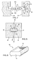
- FIG. 5 shows a seal 40 sealing between first and second members 42 and 44.
- the seal 40 spans a gap 46 between adjacent surfaces (faces) 48 and 50 of the first and second members, respectively.
- the seal 40 has a generally flat body 60 extending between first and second edge protuberances 62 and 64, respectively.
- the seal has first and second opposed faces 66 and 68 along the body and first and second ends 70 and 72 (FIG. 6).
- the seal protuberances 62 and 64 and adjacent portions of the body 60 are captured within slots 74 and 76 (FIG. 7) of the members 42 and 44.
- Each of the slots 74 and 76 has an outboard portion between a pair of opposed surfaces 80 and 82 which converge inward toward each other from the associated surface 48 or 50. At inboard ends, the slot opens up with divergent surfaces 84 and 86.
- the exemplary slots have base surfaces 88. In the illustrated example, the slots have opening heights H 1 and throat heights H 2 .
- the exemplary protuberances 62 and 64 are shown having a thickness or height H 3 .
- the exemplary body 60 is shown having a height H 4 .
- Exemplary H 3 is slightly less than H 1 and greater than H 2 .
- Exemplary relaxed H 4 may or may not be greater than the height of the component cavities at the end (e.g., it may be slightly smaller than H 2 in many cases).
- FIG. 7 further shows coordinate axes 500, 502, and 504. In an exemplary implementation, these are coincident with the ⁇ 0,0,1>, ⁇ -1,1,0>, and ⁇ 1,1,0> crystallographic axes, respectively.
- Axis 500 falls parallel to the length of the seal between the ends 70 and 72 (e.g., out of the page as used in FIG. 7).
- the axis 502 extends normal to the body 60 and its faces 66 and 58.
- the axis 504 extends toward one of the members 42 and 44. In an exemplary assembly, the members 42 and 44 are brought toward each other with the seal 40 therebetween. The seal protuberances encounter the slot outboard portion and contact the associated slot surfaces 80 and 82.
- the exemplary protuberances 62 and 64 may or may not be under compression. For example if the members 42 and 44 are pulled away from each other after the assembly, thereby relieving compression stress on the seal 40, the exemplary protuberances 62 and 64 will tend to protrude to their natural position, filling the cavity.
- Exemplary members 42 and 44 may be a pair of adjacent blade or vane platforms, shrouds, or air seal segments sealed edge-to-edge by the seal 40.
- FIG. 8 shows a seal 100 sealing between first and second members 102 and 104.
- the seal 100 spans a gap 106 between adjacent surfaces (faces) 108 and 110 of the first and second members, respectively.
- the seal 100 has a generally flat body 120 extending between first and second end portions 122 and 124.
- the body has first and second faces 126 and 128.
- Each end portion has a pair of terminal and intermediate protrusions 130 and 132, respectively, with each pair forming an associated protuberance.
- the protuberance may be formed by a protrusion extending from but a single face of the body.
- the seal 100 extends between first and second ends 140 and 142 (FIG. 9).
- An alternative configuration of the seal may be in the form of an uninterrupted ring.
- the end portions 122 and 124 and adjacent portions of the seal body 120 are captured within slots 150 and 152 (FIG. 10) in the members 102 and 104.
- the exemplary slots include recesses for retaining the seal.
- the exemplary recesses include pairs of inboard and outboard recesses 153 and 154, respectively.
- the exemplary outboard recesses 154 are near bases 156 of the associated slots.
- the exemplary recesses 153 and 154 respectively, capture the associated protrusions 130 and 132.
- FIG. 9 shows a first axis 510 along a length of the seal, a second axis 512 normal thereto and normal to the surfaces 126 and 128, and a third axis 514 normal to the first two axes.
- the first axis 510 may be a ⁇ 1,1,0> axis.
- the second axis 512 may be a ⁇ 0,0,1> axis, making the third axis 514 a ⁇ 1,-1,1,> axis.
- FIG. 10 shows the seal as having a thickness or height H 5 along the protuberances.
- the slot has a height H 6 at the recesses.
- the seal has a thickness or height H 7 along the body.
- the slot has a height H 8 away from the recesses.
- a relaxed H 5 would advantageously be greater than H 8 for retention. However, under the applied tension, H 5 may become less than H 8 thereby facilitating insertion.
- the tension may be applied via a fixture (not shown-e.g., one grasping the seal adjacent both ends). Additionally, the seal may be provided with special features for engaging the fixture. Additionally, near the ends 140, 142, the protrusions may be formed so as to taper in the relaxed state. This taper may compensate for the reduced local tension in the tensioned state and, thereby, for reduced contraction. Alternatively, the slot may be wider near the ends of the seal to address such uneven seal contraction.
- FIG. 11 shows wire seals 200, 202, 204, and 206 at various locations on a turbine engine rotor.
- the exemplary seal 200 seals an aft surface of an outboard portion of a cover plate 210 to a forward surface of peripheral portion of a disk 212.
- the exemplary seal 202 seals an aft surface of the peripheral portion of the disk 212 to a forward surface of spacer 214.
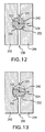
- FIG. 12 schematically shows such a wire seal 240 and the two adjacent members 242 and 244 being sealed.
- the seal may be partially captured within one or both of recesses 250 and 252 in the members.
- the seal 240 may span a gap 256 between adjacent faces of the members.
- FIG. 12 further shows a local radial (relative to the engine rotational axis/centerline) direction 520, a local circumferential direction 522, and a local aftward/downstream direction 524.
- Exemplary directions 520, 522, and 524 are ⁇ 0,0,1>, ⁇ 1,1,0>, and ⁇ -1,1,0>, respectively.
- the seal 240 may not be made as an ideal single crystal alloy.
- the crystallographic axis orientations may be achieved in one or more of several ways.
- the seal could be assembled from a number of short single crystal segments (e.g., welded end-to-end and/or mechanically interlocked). In such an assembly, along the length of each segment, the alignment of crystalline axes relative to physical axes is sufficiently close to provide desired performance.
- the seal could be made from a single crystal wire bent around, tolerating some elastic strain.
- the seal may be polycrystalline with low angle boundaries, wherein, within each of the crystals, the crystallographic and physical axes are sufficiently aligned.
- Such polycrystalline or "textured" material may be obtained in a variety of ways, such as by using special directional solidification casting techniques using a furnace moving along the circumference.
- FIG. 11 also shows a damper member 300 at an inboard end 302 of the cover plate 210.
- the exemplary inboard end 302 is at an inboard/forward end of a sleeve-like portion 304 bearing a plurality of annular sealing teeth (also known as lands or runners) 306 extending radially outward.
- the teeth 306 interface with an abradable seal material 308 held by an associated portion 310 of the engine static structure.
- Exemplary material 308 may be an abradable honeycomb material.
- Exemplary seal and teeth configuration may provide a stepped labyrinth seal profile to reduce leakage flow.
- the portion 304 may be subject to vibratory displacement as the engine runs.
- the damper may help damp such displacements.
- FIG. 14 shows the damper 300 in an initial condition wherein the engine is non-rotating.
- the damper 300 may be captured within a radially inwardly open slot 320 in the end portion 302.
- the slot 320 may have fore and aft surfaces 322 and 324 and a radially outboard base surface 326.
- Radial, circumferential, and longitudinal directions are shown as 530, 532, and 534, respectively. In the exemplary implementation, these may be ⁇ -1,1,0>, ⁇ 1,1,0>, and ⁇ 0,0,1>, respectively.
- the damper 300 may be constructed in a similar fashion to the wire seals described above.
- the exemplary damper may have a different crystallographic orientation.
- the exemplary crystallographic orientation of the damper 300 provides a longitudinal contraction (FIG. 15) responsive to the rotation-induced hoop stress.
- the contraction may at least partially release engagement between the surfaces 322 and 324. The release permits free or sliding radial displacements of the damper relative to the end portion 302, thereby permitting vibratory damping.
- FIG. 16 shows a filter element 350.
- the exemplary element includes a first arrayed group of members 352 and a second arrayed group of members 354.
- the members of each group may be parallel to each other.
- the groups may be oriented perpendicular or otherwise transverse to each other.
- the exemplary groups are overlaid. Alternatives involve intermeshing, interweaving, or even integrating.
- the exemplary members 352 may be formed of auxetic alloys as noted above.
- the members have a longitudinal direction 540, a direction 542 along the array, and a direction 544 normal thereto.
- the exemplary directions 540, 542, 544, respectively, correspond to the ⁇ 1,1,0>, ⁇ 0,0,1>, and ⁇ -1,1,0> crystallographic directions.
- the exemplary members 352 may be formed as square sectioned rods. Other configurations may alternatively be used.
- the exemplary rods 352 have a thickness T in the direction 542 and a height H in the direction 544. Gaps 356 between the rods 352 have a width W. If a tension is applied to the rods 352 along the direction 540 (FIG.17) the rods will greatly contract in the direction 542 thereby increasing the gap width W. Additionally, the rods will expand in the direction 544 thereby increasing the rod height H.
- This combination of dimensional changes may be effective to break-up deposits.
- the break-up of deposits may be particularly appropriate for one or the other of back-flush or through-flush cleaning. Particulate deposit caught between adjacent rods due to irregular shape can be dislodged as the gap width is increased.
- compression rather than tension may be utilized to dislodge deposits.
- the effects may be used to dynamically vary the pore size of the filter to achieve a specific particle size distribution. The tension or compression may be applied in a static, oscillatory or vibratory manner.
- FIG. 18 shows an FCC insert 400 in a rigid body 402.
- a ⁇ 1,1,0> direction is shown as 404 and a ⁇ 0,0,1> direction is shown as 406 for the insert 400.
- the exemplary insert is formed as a right parallelepiped having exposed face 408 facing in the direction 404.
- a second face 410 is opposite the face 408.
- Another exposed face 412 faces the direction 406 and has an opposite face 414.
- the faces 410 and 414 are respectively contacted by faces 416 and 418 of a recess in the body 402 accommodating the insert 400.
- at least one of the ends of the insert i.e., above and below the plane of the drawing) are free (unconstrained) by the body.
- An incident pulse waveform 420 (FIG. 19)is shown encountering the face 408.
- An outputted pulse waveform 422 is shown leaving the face 412.
- the large positive Poisson's effect creates an out-of-phase strain signal. Attenuation is low, so that exemplary amplitude of the pulse 422 typically greater than 50% of the amplitude of pulse 420, such as about 70%.
- FIG. 20 shows an insert 400' receiving a similar pulse 420 on a first face 408.
- the crystal orientation of the insert 400' is such that the other exposed face 412' faces a ⁇ -1,1,0> direction.
- the negative Poisson's effect creates an in-phase strain signal (FIG. 21). Attenuation is great, so that exemplary amplitude of the pulse 422' is typically less than 50% of the amplitude of pulse 420 (e.g., 20% or less, such as about 12%).
- vibration is advantageously transmitted to or from a hostile environment (e.g., a high temperature and/or chemically hostile location).
- a hostile environment e.g., a high temperature and/or chemically hostile location.
- much existing sensor and transducer technology can't be used in high temperature environments. Therefore, it is advantageous to transmit the vibration between the high temperature environment and a remotely located sensor or transducer.
- Some transmission examples involve real-time inspection (e.g., inspecting gas turbine engine components while the engine is operating).
- a transducer sends a vibration to a component.
- a sensor receives a return or transmitted vibration to facilitate analysis of component condition.
- a component is subject to operational vibration.
- a sensor receives vibration from the component. Responsive to the sensed vibration, a transducer sends a vibration to the component to at least partially cancel the operational vibration.
- appropriately oriented single crystal rods of nickel and iron based alloys with ceramic sleeves or thermal barrier coatings may be used to transmit vibration to/from the subject component.
- a rod could be positioned to transmit vibration between the component and the associated face of the fcc insert (e.g., of FIGS. 18 and 20).
- the sensor or transducer could be mounted to the other face either directly or via another intervening member.
- FIG. 22 shows one example of such an assembly.
- the assembly 603 has a rigid single crystal bar 600 laterally enveloped by a hexagonal-sectioned sheetmetal sleeve/jacket 602 along a portion of the bar's length.
- the sleeve/jacket can be a different material bonded to the single crystal bar along the edge faces 608 and 610.
- the sleeve/jacket can be an integral part of the single crystal body (e.g., unitarily cast and/or machined therewith).
- the exemplary bar 600 is a right parallelepiped.
- the longest dimension is through the sleeve and the parallelepiped has first and second principal faces 604 and 606, first and second edge faces 608 and 610, and first and second end faces 612 and 614.
- FIG. 22 shows a lengthwise direction 616, a heightwise direction 617 and a widthwise direction 618. In the exemplary implementation, these directions are respectively ⁇ 1,1,0>, ⁇ 0,0,1>, and ⁇ -1,1,0>.
- the sleeve 602 has interior and exterior surfaces 620 and 622 and first and second ends 624 and 626. Portions 630 and 631 of the bar protrude beyond the ends 624 and 626, respectively.
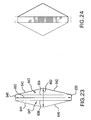
- FIG. 23 is an end view of the assembly in a relaxed state. The sleeve is shown having sections (sides of the hexagon) 640 and 642 adjacent the bar side 640 and cooperating therewith to define a cavity 643. Similarly, sections 644 and 646 cooperate with the face 606 to define a cavity 647. Sections 648 and 650 lie along the edges 608 and 610. The bar may be put under longitudinal tension (e.g., by pulling on the end portions 630 and 632). FIG.
- FIG. 24 shows the tensioned bar if a large positive Poisson's strain is realized. If the ratio of the height 660 to the width 662 of the sleeve is ten, then the Poisson's displacement along the direction 617 is approximately augmented by ten times in the direction 618.
- FIG. 25 shows a relaxed condition of an assembly 670 comprising a plurality of subassemblies 603.
- FIG. 26 shows the assembly 670 in a strained condition.
- the exemplary transverse dimensions of the individual assembly 603 are fairly small (e.g., 0.1-3.0mm relaxed width or height).
- the transverse dimensions of the assemblies 670 may be much larger (e.g., 210mm or more).
- the assembly 670 may be formed as near-round rods of effective relaxed diameter 0.2-2.5mm.
Landscapes
- Engineering & Computer Science (AREA)
- General Engineering & Computer Science (AREA)
- Mechanical Engineering (AREA)
- Chemical & Material Sciences (AREA)
- Combustion & Propulsion (AREA)
- Physics & Mathematics (AREA)
- General Physics & Mathematics (AREA)
- Acoustics & Sound (AREA)
- Multimedia (AREA)
- Turbine Rotor Nozzle Sealing (AREA)
- Gasket Seals (AREA)
- Crystals, And After-Treatments Of Crystals (AREA)
Applications Claiming Priority (1)
| Application Number | Priority Date | Filing Date | Title |
|---|---|---|---|
| US11/486,743 US8016549B2 (en) | 2006-07-13 | 2006-07-13 | Turbine engine alloys and crystalline orientations |
Publications (3)
| Publication Number | Publication Date |
|---|---|
| EP1878873A2 true EP1878873A2 (fr) | 2008-01-16 |
| EP1878873A3 EP1878873A3 (fr) | 2011-08-10 |
| EP1878873B1 EP1878873B1 (fr) | 2016-08-31 |
Family
ID=38508702
Family Applications (1)
| Application Number | Title | Priority Date | Filing Date |
|---|---|---|---|
| EP07252722.9A Active EP1878873B1 (fr) | 2006-07-13 | 2007-07-06 | Procédé de conception d'une garniture métallique d'étanchéité coulée monocristalline pour un moteur à turbine à gaz et dispositif comprenant une garniture associée |
Country Status (3)
| Country | Link |
|---|---|
| US (1) | US8016549B2 (fr) |
| EP (1) | EP1878873B1 (fr) |
| JP (1) | JP4621711B2 (fr) |
Cited By (15)
| Publication number | Priority date | Publication date | Assignee | Title |
|---|---|---|---|---|
| CN102678190A (zh) * | 2011-02-14 | 2012-09-19 | 通用电气公司 | 涡轮叶片平台的构件 |
| DE102011108957A1 (de) | 2011-07-29 | 2013-01-31 | Mtu Aero Engines Gmbh | Verfahren zum Herstellen, Reparieren und/oder Austauschen eines Gehäuses, insbesondere eines Triebwerkgehäuses, sowie ein entsprechendes Gehäuse |
| DE102011084125A1 (de) * | 2011-10-07 | 2013-04-11 | Mtu Aero Engines Gmbh | Schaufelsegment und Strömungsmaschine |
| WO2015052005A1 (fr) * | 2013-10-11 | 2015-04-16 | Robert Bosch Gmbh | Soupape de commande |
| WO2015073655A1 (fr) * | 2013-11-15 | 2015-05-21 | Bha Altair, Llc | Système de filtration pour turbine à gaz avec un ensemble d'orientation de filtre d'admission |
| RU2586805C2 (ru) * | 2010-07-13 | 2016-06-10 | Сименс Акциенгезелльшафт | Уплотнительный элемент для уплотнения зазора |
| EP3085902A1 (fr) * | 2015-04-24 | 2016-10-26 | United Technologies Corporation | Structure de grain de cristal unique et procédé de formation de joints d'étanchéité |
| EP3109403A1 (fr) * | 2015-06-24 | 2016-12-28 | United Technologies Corporation | Joint de rotor à lame réversible avec des saillies |
| EP3141700A1 (fr) * | 2015-08-13 | 2017-03-15 | United Technologies Corporation | Orientation cristalline d'étanchéité pour une meilleure conformité |
| EP3196322A1 (fr) * | 2016-01-22 | 2017-07-26 | United Technologies Corporation | Joint mince pour une turbine à gaz |
| WO2017178203A1 (fr) * | 2016-04-12 | 2017-10-19 | Siemens Aktiengesellschaft | Aube de turbine, dispositif associé, turbomachine et utilisation |
| EP3239473A1 (fr) * | 2016-04-25 | 2017-11-01 | United Technologies Corporation | Joint haute température et procédé |
| FR3065986A1 (fr) * | 2017-05-02 | 2018-11-09 | Safran Aircraft Engines | Ensemble pour turbine a gaz, turbine a gaz associee |
| EP3470633A1 (fr) * | 2017-10-11 | 2019-04-17 | United Technologies Corporation | Joint de piston résistant à l'usure |
| US11771183B2 (en) | 2021-12-16 | 2023-10-03 | Joon Bu Park | Negative Poisson's ratio materials for fasteners |
Families Citing this family (34)
| Publication number | Priority date | Publication date | Assignee | Title |
|---|---|---|---|---|
| JP5308679B2 (ja) * | 2008-01-22 | 2013-10-09 | 東京エレクトロン株式会社 | シール機構、シール溝、シール部材及び基板処理装置 |
| US20090191050A1 (en) * | 2008-01-24 | 2009-07-30 | Siemens Power Generation, Inc. | Sealing band having bendable tang with anti-rotation in a turbine and associated methods |
| FR2955142B1 (fr) * | 2010-01-13 | 2013-08-23 | Snecma | Amortisseur de vibrations a pion entre talons d'aubes adjacentes en materiau composite d'une roue mobile de turbomachine. |
| US9534500B2 (en) * | 2011-04-27 | 2017-01-03 | Pratt & Whitney Canada Corp. | Seal arrangement for segmented gas turbine engine components |
| US9551049B2 (en) | 2012-08-28 | 2017-01-24 | United Technologies Corporation | High elastic modulus shafts and method of manufacture |
| US9541148B1 (en) | 2012-08-29 | 2017-01-10 | The United States Of America As Represented By The Administrator Of National Aeronautics And Space Administration | Process for forming a high temperature single crystal canted spring |
| EP2971611B1 (fr) | 2013-03-14 | 2019-10-02 | United Technologies Corporation | Moteur turbine avec bride de carter multicouche |
| US9709274B2 (en) * | 2013-03-15 | 2017-07-18 | Rolls-Royce Plc | Auxetic structure with stress-relief features |
| CA2907048A1 (fr) * | 2013-03-15 | 2014-09-25 | President And Fellows Of Harvard College | Feuille auxetique a faible porosite |
| US9416675B2 (en) * | 2014-01-27 | 2016-08-16 | General Electric Company | Sealing device for providing a seal in a turbomachine |
| US9719363B2 (en) * | 2014-06-06 | 2017-08-01 | United Technologies Corporation | Segmented rim seal spacer for a gas turbine engine |
| EP3245055B1 (fr) | 2015-01-09 | 2019-08-21 | President and Fellows of Harvard College | Structures auxétiques à vide et alvéole hyrbrides ayant des motifs mis au point pour un comportement npr pesonnalisé |
| EP3242794B1 (fr) | 2015-01-09 | 2020-12-30 | President and Fellows of Harvard College | Structure npr à porosité nulle et réglage de structure npr pour des régions particulières |
| CA2973402A1 (fr) | 2015-01-09 | 2016-07-14 | President And Fellows Of Harvard College | Structures gaufrees a coefficient de poisson negatif |
| US9970308B2 (en) * | 2015-01-26 | 2018-05-15 | United Technologies Corporation | Feather seal |
| US10487677B2 (en) * | 2015-11-10 | 2019-11-26 | General Electric Company | Turbine component having a seal slot and additive manufacturing process for making same |
| WO2017095926A1 (fr) | 2015-12-01 | 2017-06-08 | Saint-Gobain Performance Plastics Corporation | Joints annulaires |
| GB201603554D0 (en) | 2016-03-01 | 2016-04-13 | Rolls Royce Plc | An intercomponent seal for a gas turbine engine |
| US10487943B2 (en) * | 2016-07-12 | 2019-11-26 | United Technologies Corporation | Multi-ply seal ring |
| US11181002B2 (en) * | 2016-09-29 | 2021-11-23 | General Electric Company | Turbine systems with sealing components |
| US11208907B2 (en) * | 2017-07-13 | 2021-12-28 | Raytheon Technologies Corporation | Seals and methods of making seals |
| FR3071272B1 (fr) * | 2017-09-21 | 2019-09-20 | Safran | Piece de turbine en superalliage comprenant du rhenium et/ou du ruthenium et procede de fabrication associe |
| US11220919B2 (en) | 2019-07-18 | 2022-01-11 | Pratt & Whtney Canada Corp. | Method of making a single-crystal turbine blade |
| FR3100560B1 (fr) * | 2019-09-06 | 2022-04-29 | Safran Aircraft Engines | Ensemble pour une turbine de turbomachine |
| US12104533B2 (en) * | 2020-04-24 | 2024-10-01 | General Electric Company | Methods and apparatus for gas turbine frame flow path hardware cooling |
| US11313281B2 (en) * | 2020-07-16 | 2022-04-26 | Raytheon Technologies Corporation | Gas turbine engine including seal assembly with abradable coating including magnetic particles |
| US11293351B2 (en) * | 2020-07-16 | 2022-04-05 | Raytheon Technologies Corporation | Gas turbine engine including seal assembly with abradable coating including magnetic particles embedded in polymer |
| US11313280B2 (en) * | 2020-07-16 | 2022-04-26 | Raytheon Technologies Corporation | Gas turbine engine including seal assembly with abradable coating and cutter |
| US12085169B2 (en) * | 2020-09-25 | 2024-09-10 | Flowserve Pte. Ltd. | Pressure retained gasket seal with enhanced unloading resistance |
| EP4074941A1 (fr) * | 2021-04-13 | 2022-10-19 | Siemens Energy Global GmbH & Co. KG | Élément de bande d'étanchéité et agencement d'étanchéité comprenant ledit élément de bande d'étanchéité |
| US11905842B2 (en) | 2021-12-16 | 2024-02-20 | General Electric Company | Partition damper seal configurations for segmented internal cooling hardware |
| US12366201B2 (en) | 2023-02-17 | 2025-07-22 | General Electric Company | Reverse flow gas turbine engine having electric machine |
| US12319417B2 (en) | 2023-02-17 | 2025-06-03 | General Electric Company | Reverse flow gas turbine engine having electric machine |
| US20250109690A1 (en) * | 2023-10-03 | 2025-04-03 | General Electric Company | Turbine engine with compliant axial retainer |
Family Cites Families (13)
| Publication number | Priority date | Publication date | Assignee | Title |
|---|---|---|---|---|
| US4605452A (en) * | 1981-12-14 | 1986-08-12 | United Technologies Corporation | Single crystal articles having controlled secondary crystallographic orientation |
| SE8107724L (sv) * | 1981-12-22 | 1983-06-23 | Mecman Ab | Anordning vid en kolvstangslos tryckmediecylinder |
| US4668557A (en) | 1986-07-18 | 1987-05-26 | The University Of Iowa Research Foundation | Polyhedron cell structure and method of making same |
| GB8916231D0 (en) | 1989-07-14 | 1989-08-31 | Evans Kenneth E | Polymeric materials |
| US5158430A (en) * | 1990-09-12 | 1992-10-27 | United Technologies Corporation | Segmented stator vane seal |
| DE19537282C2 (de) | 1995-10-06 | 1999-02-18 | Mtu Muenchen Gmbh | Vorrichtung zur Abdichtung eines Ringraumes gegen Beaufschlagung durch Fluid |
| US6199871B1 (en) | 1998-09-02 | 2001-03-13 | General Electric Company | High excursion ring seal |
| US6447871B1 (en) | 1999-09-27 | 2002-09-10 | The Aerospace Corporation | Composite materials with embedded machines |
| US6883807B2 (en) | 2002-09-13 | 2005-04-26 | Seimens Westinghouse Power Corporation | Multidirectional turbine shim seal |
| GB0228748D0 (en) | 2002-12-10 | 2003-01-15 | Alstom Switzerland Ltd | Sealing arrangement |
| US20050224144A1 (en) | 2004-01-16 | 2005-10-13 | Tresa Pollock | Monocrystalline alloys with controlled partitioning |
| US20050198904A1 (en) | 2004-03-12 | 2005-09-15 | Browne Alan L. | Active seal assemblies for movable windows |
| US20060082074A1 (en) | 2004-10-18 | 2006-04-20 | Pratt & Whitney Canada Corp. | Circumferential feather seal |
-
2006
- 2006-07-13 US US11/486,743 patent/US8016549B2/en active Active
-
2007
- 2007-06-26 JP JP2007167050A patent/JP4621711B2/ja not_active Expired - Fee Related
- 2007-07-06 EP EP07252722.9A patent/EP1878873B1/fr active Active
Cited By (27)
| Publication number | Priority date | Publication date | Assignee | Title |
|---|---|---|---|---|
| RU2586805C2 (ru) * | 2010-07-13 | 2016-06-10 | Сименс Акциенгезелльшафт | Уплотнительный элемент для уплотнения зазора |
| CN102678190B (zh) * | 2011-02-14 | 2015-12-16 | 通用电气公司 | 涡轮叶片平台的构件 |
| CN102678190A (zh) * | 2011-02-14 | 2012-09-19 | 通用电气公司 | 涡轮叶片平台的构件 |
| DE102011108957B4 (de) * | 2011-07-29 | 2013-07-04 | Mtu Aero Engines Gmbh | Verfahren zum Herstellen, Reparieren und/oder Austauschen eines Gehäuses, insbesondere eines Triebwerkgehäuses, sowie ein entsprechendes Gehäuse |
| WO2013017118A1 (fr) | 2011-07-29 | 2013-02-07 | Mtu Aero Engines Gmbh | Procédé de fabrication, de réparation et/ou de remplacement d'un corps, en particulier d'un corps de propulseur, ainsi que corps correspondant |
| DE102011108957A1 (de) | 2011-07-29 | 2013-01-31 | Mtu Aero Engines Gmbh | Verfahren zum Herstellen, Reparieren und/oder Austauschen eines Gehäuses, insbesondere eines Triebwerkgehäuses, sowie ein entsprechendes Gehäuse |
| US10066508B2 (en) | 2011-07-29 | 2018-09-04 | MTU Aero Engines AG | Method for producing, repairing and/or exchanging a housing, in particular an engine housing, and a corresponding housing |
| DE102011084125A1 (de) * | 2011-10-07 | 2013-04-11 | Mtu Aero Engines Gmbh | Schaufelsegment und Strömungsmaschine |
| WO2015052005A1 (fr) * | 2013-10-11 | 2015-04-16 | Robert Bosch Gmbh | Soupape de commande |
| WO2015073655A1 (fr) * | 2013-11-15 | 2015-05-21 | Bha Altair, Llc | Système de filtration pour turbine à gaz avec un ensemble d'orientation de filtre d'admission |
| US9358488B2 (en) | 2013-11-15 | 2016-06-07 | Bha Altair, Llc | Gas turbine filtration system with inlet filter orientation assembly |
| US10323572B2 (en) | 2013-11-15 | 2019-06-18 | Bha Altair, Llc | Gas turbine filtration system with inlet filter orientation assembly |
| EP3085902A1 (fr) * | 2015-04-24 | 2016-10-26 | United Technologies Corporation | Structure de grain de cristal unique et procédé de formation de joints d'étanchéité |
| US10830357B2 (en) | 2015-04-24 | 2020-11-10 | Raytheon Technologies Corporation | Single crystal grain structure seals and method of forming |
| US9810087B2 (en) | 2015-06-24 | 2017-11-07 | United Technologies Corporation | Reversible blade rotor seal with protrusions |
| EP3109403A1 (fr) * | 2015-06-24 | 2016-12-28 | United Technologies Corporation | Joint de rotor à lame réversible avec des saillies |
| EP3141700A1 (fr) * | 2015-08-13 | 2017-03-15 | United Technologies Corporation | Orientation cristalline d'étanchéité pour une meilleure conformité |
| EP3196322A1 (fr) * | 2016-01-22 | 2017-07-26 | United Technologies Corporation | Joint mince pour une turbine à gaz |
| CN109072708A (zh) * | 2016-04-12 | 2018-12-21 | 西门子股份公司 | 涡轮机叶片、所属的设备、流体机械和应用 |
| WO2017178203A1 (fr) * | 2016-04-12 | 2017-10-19 | Siemens Aktiengesellschaft | Aube de turbine, dispositif associé, turbomachine et utilisation |
| EP3239473A1 (fr) * | 2016-04-25 | 2017-11-01 | United Technologies Corporation | Joint haute température et procédé |
| US10352183B2 (en) | 2016-04-25 | 2019-07-16 | United Technologies Corporation | High temperature seal and method |
| FR3065986A1 (fr) * | 2017-05-02 | 2018-11-09 | Safran Aircraft Engines | Ensemble pour turbine a gaz, turbine a gaz associee |
| US10760440B2 (en) | 2017-05-02 | 2020-09-01 | Safran Aircraft Engines | Assembly for gas turbine, associated gas turbine |
| EP3470633A1 (fr) * | 2017-10-11 | 2019-04-17 | United Technologies Corporation | Joint de piston résistant à l'usure |
| US11771183B2 (en) | 2021-12-16 | 2023-10-03 | Joon Bu Park | Negative Poisson's ratio materials for fasteners |
| US12070104B2 (en) | 2021-12-16 | 2024-08-27 | Joon Bu Park | Negative Poisson's ratio materials for fasteners |
Also Published As
| Publication number | Publication date |
|---|---|
| EP1878873A3 (fr) | 2011-08-10 |
| JP2008019860A (ja) | 2008-01-31 |
| EP1878873B1 (fr) | 2016-08-31 |
| US20110081235A1 (en) | 2011-04-07 |
| JP4621711B2 (ja) | 2011-01-26 |
| US8016549B2 (en) | 2011-09-13 |
Similar Documents
| Publication | Publication Date | Title |
|---|---|---|
| US8016549B2 (en) | Turbine engine alloys and crystalline orientations | |
| EP2518274B1 (fr) | Contrôle de jeu de pale à l'aide d'éléments en anneau avec CTE élevé et CTE faible | |
| EP2535522B1 (fr) | Ensemble d'étanchéité comprenant un joint en forme de w | |
| US10465545B2 (en) | Thin seal for an engine | |
| Wijesundara et al. | Silicon carbide microsystems for harsh environments | |
| US6039325A (en) | Resilient braided rope seal | |
| Basu et al. | Hysteresis and bristle stiffening effects in brush seals | |
| EP2324205B1 (fr) | Dispositif amortisseur de vibrations pour attaches d'aubes de turbomachine, turbomachine et moteurs associes | |
| Vance et al. | A new damper seal for turbomachinery | |
| JP2018184338A (ja) | セグメント化された環境バリアコーティングシステムおよびその形成方法 | |
| JP2012140937A (ja) | 構造的に低延性のタービンシュラウド装置 | |
| Šmíd et al. | High cycle fatigue of nickel-based superalloy MAR-M 247 at high temperatures | |
| US20180283212A1 (en) | System and method for attaching a non-metal component to a metal component | |
| Carlin et al. | Effects of tensioning on buckling and vibration of circular saw blades | |
| EP3063110B1 (fr) | Articles formant silice ayant des surfaces modifiées pour améliorer la résistance au glissement du fluage sous des charges à hautes températures | |
| EP2236770B1 (fr) | Elément d'un turboréacteur avec une microstructure cristalline | |
| EP2698446A2 (fr) | Revêtements de barrière environnementale résistant aux fissures | |
| EP3239473B1 (fr) | Joint haute température et procédé | |
| Chupp et al. | Turbomachinery clearance control | |
| US20050281677A1 (en) | Powder/wrought alloy composite turbine disc | |
| Grünling et al. | Some practical aspects of corrosion and coatings in utility gas turbines | |
| US20260117667A1 (en) | Methods and apparatus to reduce vibration of a radial seal in a gas turbine engine | |
| Harrison et al. | Modelling of thermomechanical fatigue in aero engine turbine blades | |
| Saiteja et al. | Determining Hysteresis Damping in a Steam Turbine Blade using a Finite Element Tool | |
| Chen et al. | Natural frequency of stepped beam having multiple open cracks by transfer matrix method |
Legal Events
| Date | Code | Title | Description |
|---|---|---|---|
| PUAI | Public reference made under article 153(3) epc to a published international application that has entered the european phase |
Free format text: ORIGINAL CODE: 0009012 |
|
| AK | Designated contracting states |
Kind code of ref document: A2 Designated state(s): AT BE BG CH CY CZ DE DK EE ES FI FR GB GR HU IE IS IT LI LT LU LV MC MT NL PL PT RO SE SI SK TR |
|
| AX | Request for extension of the european patent |
Extension state: AL BA HR MK YU |
|
| RIC1 | Information provided on ipc code assigned before grant |
Ipc: F01D 5/14 20060101AFI20070924BHEP Ipc: F16J 15/06 20060101ALI20090519BHEP Ipc: F01D 5/28 20060101ALI20090519BHEP |
|
| PUAL | Search report despatched |
Free format text: ORIGINAL CODE: 0009013 |
|
| RIC1 | Information provided on ipc code assigned before grant |
Ipc: F01D 5/14 20060101AFI20110630BHEP Ipc: F01D 5/28 20060101ALI20110630BHEP Ipc: F16J 15/06 20060101ALI20110630BHEP |
|
| AK | Designated contracting states |
Kind code of ref document: A3 Designated state(s): AT BE BG CH CY CZ DE DK EE ES FI FR GB GR HU IE IS IT LI LT LU LV MC MT NL PL PT RO SE SI SK TR |
|
| AX | Request for extension of the european patent |
Extension state: AL BA HR MK RS |
|
| 17P | Request for examination filed |
Effective date: 20120209 |
|
| AKX | Designation fees paid |
Designated state(s): DE GB |
|
| REG | Reference to a national code |
Ref country code: DE Ref legal event code: R079 Ref document number: 602007047699 Country of ref document: DE Free format text: PREVIOUS MAIN CLASS: F01D0005140000 Ipc: F01D0011000000 |
|
| RIC1 | Information provided on ipc code assigned before grant |
Ipc: F01D 11/00 20060101AFI20160104BHEP |
|
| GRAP | Despatch of communication of intention to grant a patent |
Free format text: ORIGINAL CODE: EPIDOSNIGR1 |
|
| INTG | Intention to grant announced |
Effective date: 20160215 |
|
| GRAS | Grant fee paid |
Free format text: ORIGINAL CODE: EPIDOSNIGR3 |
|
| GRAA | (expected) grant |
Free format text: ORIGINAL CODE: 0009210 |
|
| AK | Designated contracting states |
Kind code of ref document: B1 Designated state(s): DE GB |
|
| REG | Reference to a national code |
Ref country code: GB Ref legal event code: FG4D |
|
| REG | Reference to a national code |
Ref country code: DE Ref legal event code: R096 Ref document number: 602007047699 Country of ref document: DE |
|
| RAP2 | Party data changed (patent owner data changed or rights of a patent transferred) |
Owner name: UNITED TECHNOLOGIES CORPORATION |
|
| REG | Reference to a national code |
Ref country code: DE Ref legal event code: R097 Ref document number: 602007047699 Country of ref document: DE |
|
| PLBE | No opposition filed within time limit |
Free format text: ORIGINAL CODE: 0009261 |
|
| STAA | Information on the status of an ep patent application or granted ep patent |
Free format text: STATUS: NO OPPOSITION FILED WITHIN TIME LIMIT |
|
| REG | Reference to a national code |
Ref country code: DE Ref legal event code: R082 Ref document number: 602007047699 Country of ref document: DE Representative=s name: SCHMITT-NILSON SCHRAUD WAIBEL WOHLFROM PATENTA, DE |
|
| 26N | No opposition filed |
Effective date: 20170601 |
|
| PGFP | Annual fee paid to national office [announced via postgrant information from national office to epo] |
Ref country code: DE Payment date: 20200622 Year of fee payment: 14 |
|
| REG | Reference to a national code |
Ref country code: DE Ref legal event code: R119 Ref document number: 602007047699 Country of ref document: DE |
|
| PG25 | Lapsed in a contracting state [announced via postgrant information from national office to epo] |
Ref country code: DE Free format text: LAPSE BECAUSE OF NON-PAYMENT OF DUE FEES Effective date: 20220201 |
|
| PGFP | Annual fee paid to national office [announced via postgrant information from national office to epo] |
Ref country code: GB Payment date: 20250619 Year of fee payment: 19 |
|
| P01 | Opt-out of the competence of the unified patent court (upc) registered |
Free format text: CASE NUMBER: UPC_APP_0018194_1878873/2025 Effective date: 20251218 |