EP3085902A1 - Structure de grain de cristal unique et procédé de formation de joints d'étanchéité - Google Patents
Structure de grain de cristal unique et procédé de formation de joints d'étanchéité Download PDFInfo
- Publication number
- EP3085902A1 EP3085902A1 EP16166894.2A EP16166894A EP3085902A1 EP 3085902 A1 EP3085902 A1 EP 3085902A1 EP 16166894 A EP16166894 A EP 16166894A EP 3085902 A1 EP3085902 A1 EP 3085902A1
- Authority
- EP
- European Patent Office
- Prior art keywords
- seal
- cross
- single crystal
- crystal grain
- sectional shape
- Prior art date
- Legal status (The legal status is an assumption and is not a legal conclusion. Google has not performed a legal analysis and makes no representation as to the accuracy of the status listed.)
- Granted
Links
Images


Classifications
-
- C—CHEMISTRY; METALLURGY
- C30—CRYSTAL GROWTH
- C30B—SINGLE-CRYSTAL GROWTH; UNIDIRECTIONAL SOLIDIFICATION OF EUTECTIC MATERIAL OR UNIDIRECTIONAL DEMIXING OF EUTECTOID MATERIAL; REFINING BY ZONE-MELTING OF MATERIAL; PRODUCTION OF A HOMOGENEOUS POLYCRYSTALLINE MATERIAL WITH DEFINED STRUCTURE; SINGLE CRYSTALS OR HOMOGENEOUS POLYCRYSTALLINE MATERIAL WITH DEFINED STRUCTURE; AFTER-TREATMENT OF SINGLE CRYSTALS OR A HOMOGENEOUS POLYCRYSTALLINE MATERIAL WITH DEFINED STRUCTURE; APPARATUS THEREFOR
- C30B29/00—Single crystals or homogeneous polycrystalline material with defined structure characterised by the material or by their shape
- C30B29/10—Inorganic compounds or compositions
- C30B29/52—Alloys
-
- F—MECHANICAL ENGINEERING; LIGHTING; HEATING; WEAPONS; BLASTING
- F16—ENGINEERING ELEMENTS AND UNITS; GENERAL MEASURES FOR PRODUCING AND MAINTAINING EFFECTIVE FUNCTIONING OF MACHINES OR INSTALLATIONS; THERMAL INSULATION IN GENERAL
- F16J—PISTONS; CYLINDERS; SEALINGS
- F16J15/00—Sealings
- F16J15/02—Sealings between relatively-stationary surfaces
- F16J15/06—Sealings between relatively-stationary surfaces with solid packing compressed between sealing surfaces
- F16J15/08—Sealings between relatively-stationary surfaces with solid packing compressed between sealing surfaces with exclusively metal packing
- F16J15/0887—Sealings between relatively-stationary surfaces with solid packing compressed between sealing surfaces with exclusively metal packing the sealing effect being obtained by elastic deformation of the packing
-
- B—PERFORMING OPERATIONS; TRANSPORTING
- B21—MECHANICAL METAL-WORKING WITHOUT ESSENTIALLY REMOVING MATERIAL; PUNCHING METAL
- B21B—ROLLING OF METAL
- B21B1/00—Metal-rolling methods or mills for making semi-finished products of solid or profiled cross-section; Sequence of operations in milling trains; Layout of rolling-mill plant, e.g. grouping of stands; Succession of passes or of sectional pass alternations
- B21B1/46—Metal-rolling methods or mills for making semi-finished products of solid or profiled cross-section; Sequence of operations in milling trains; Layout of rolling-mill plant, e.g. grouping of stands; Succession of passes or of sectional pass alternations for rolling metal immediately subsequent to continuous casting
-
- C—CHEMISTRY; METALLURGY
- C30—CRYSTAL GROWTH
- C30B—SINGLE-CRYSTAL GROWTH; UNIDIRECTIONAL SOLIDIFICATION OF EUTECTIC MATERIAL OR UNIDIRECTIONAL DEMIXING OF EUTECTOID MATERIAL; REFINING BY ZONE-MELTING OF MATERIAL; PRODUCTION OF A HOMOGENEOUS POLYCRYSTALLINE MATERIAL WITH DEFINED STRUCTURE; SINGLE CRYSTALS OR HOMOGENEOUS POLYCRYSTALLINE MATERIAL WITH DEFINED STRUCTURE; AFTER-TREATMENT OF SINGLE CRYSTALS OR A HOMOGENEOUS POLYCRYSTALLINE MATERIAL WITH DEFINED STRUCTURE; APPARATUS THEREFOR
- C30B11/00—Single-crystal growth by normal freezing or freezing under temperature gradient, e.g. Bridgman-Stockbarger method
- C30B11/14—Single-crystal growth by normal freezing or freezing under temperature gradient, e.g. Bridgman-Stockbarger method characterised by the seed, e.g. its crystallographic orientation
-
- C—CHEMISTRY; METALLURGY
- C30—CRYSTAL GROWTH
- C30B—SINGLE-CRYSTAL GROWTH; UNIDIRECTIONAL SOLIDIFICATION OF EUTECTIC MATERIAL OR UNIDIRECTIONAL DEMIXING OF EUTECTOID MATERIAL; REFINING BY ZONE-MELTING OF MATERIAL; PRODUCTION OF A HOMOGENEOUS POLYCRYSTALLINE MATERIAL WITH DEFINED STRUCTURE; SINGLE CRYSTALS OR HOMOGENEOUS POLYCRYSTALLINE MATERIAL WITH DEFINED STRUCTURE; AFTER-TREATMENT OF SINGLE CRYSTALS OR A HOMOGENEOUS POLYCRYSTALLINE MATERIAL WITH DEFINED STRUCTURE; APPARATUS THEREFOR
- C30B33/00—After-treatment of single crystals or homogeneous polycrystalline material with defined structure
-
- F—MECHANICAL ENGINEERING; LIGHTING; HEATING; WEAPONS; BLASTING
- F01—MACHINES OR ENGINES IN GENERAL; ENGINE PLANTS IN GENERAL; STEAM ENGINES
- F01D—NON-POSITIVE DISPLACEMENT MACHINES OR ENGINES, e.g. STEAM TURBINES
- F01D11/00—Preventing or minimising internal leakage of working-fluid, e.g. between stages
- F01D11/005—Sealing means between non relatively rotating elements
-
- F—MECHANICAL ENGINEERING; LIGHTING; HEATING; WEAPONS; BLASTING
- F16—ENGINEERING ELEMENTS AND UNITS; GENERAL MEASURES FOR PRODUCING AND MAINTAINING EFFECTIVE FUNCTIONING OF MACHINES OR INSTALLATIONS; THERMAL INSULATION IN GENERAL
- F16J—PISTONS; CYLINDERS; SEALINGS
- F16J15/00—Sealings
- F16J15/02—Sealings between relatively-stationary surfaces
- F16J15/021—Sealings between relatively-stationary surfaces with elastic packing
- F16J15/022—Sealings between relatively-stationary surfaces with elastic packing characterised by structure or material
-
- F—MECHANICAL ENGINEERING; LIGHTING; HEATING; WEAPONS; BLASTING
- F05—INDEXING SCHEMES RELATING TO ENGINES OR PUMPS IN VARIOUS SUBCLASSES OF CLASSES F01-F04
- F05D—INDEXING SCHEME FOR ASPECTS RELATING TO NON-POSITIVE-DISPLACEMENT MACHINES OR ENGINES, GAS-TURBINES OR JET-PROPULSION PLANTS
- F05D2220/00—Application
- F05D2220/30—Application in turbines
- F05D2220/32—Application in turbines in gas turbines
-
- F—MECHANICAL ENGINEERING; LIGHTING; HEATING; WEAPONS; BLASTING
- F05—INDEXING SCHEMES RELATING TO ENGINES OR PUMPS IN VARIOUS SUBCLASSES OF CLASSES F01-F04
- F05D—INDEXING SCHEME FOR ASPECTS RELATING TO NON-POSITIVE-DISPLACEMENT MACHINES OR ENGINES, GAS-TURBINES OR JET-PROPULSION PLANTS
- F05D2240/00—Components
- F05D2240/55—Seals
-
- F—MECHANICAL ENGINEERING; LIGHTING; HEATING; WEAPONS; BLASTING
- F05—INDEXING SCHEMES RELATING TO ENGINES OR PUMPS IN VARIOUS SUBCLASSES OF CLASSES F01-F04
- F05D—INDEXING SCHEME FOR ASPECTS RELATING TO NON-POSITIVE-DISPLACEMENT MACHINES OR ENGINES, GAS-TURBINES OR JET-PROPULSION PLANTS
- F05D2300/00—Materials; Properties thereof
- F05D2300/60—Properties or characteristics given to material by treatment or manufacturing
- F05D2300/607—Monocrystallinity
-
- Y—GENERAL TAGGING OF NEW TECHNOLOGICAL DEVELOPMENTS; GENERAL TAGGING OF CROSS-SECTIONAL TECHNOLOGIES SPANNING OVER SEVERAL SECTIONS OF THE IPC; TECHNICAL SUBJECTS COVERED BY FORMER USPC CROSS-REFERENCE ART COLLECTIONS [XRACs] AND DIGESTS
- Y02—TECHNOLOGIES OR APPLICATIONS FOR MITIGATION OR ADAPTATION AGAINST CLIMATE CHANGE
- Y02T—CLIMATE CHANGE MITIGATION TECHNOLOGIES RELATED TO TRANSPORTATION
- Y02T50/00—Aeronautics or air transport
- Y02T50/60—Efficient propulsion technologies, e.g. for aircraft
Definitions
- the present disclosure relates to advanced materials, particularly single crystal grain structures including the formation and use of single crystal grain structures.
- Advanced technology systems such as gas turbine engines used in modem aircraft and sea vessels, in power generation operations, and in industrial applications, operate in environments with extremely high temperatures and pressures. Under these extreme conditions, many of the components within these advanced technology systems experience creep: a physical deformation of the components due to any combination of time, temperature, and stress. Creep can ultimately lead to mechanical failure of the components.
- One embodiment is directed to a seal.
- the seal includes a leading edge and a trailing edge.
- the seal further includes a seal body between the leading edge and the trailing edge.
- the seal body has a cross-sectional shape.
- the seal body is formed of a single crystal grain structure, the single crystal grain structure oriented in a direction following the cross-sectional shape of the seal body.
- the single crystal grain structure seal includes a first end and a second end.
- the seal further includes a cross-sectional shape.
- the cross-sectional shape is a two-dimensional shape represented by a cross-section of the single crystal grain structure seal. This cross-sectional shape is substantially the same at the first end, the second end, and a plurality of locations along the single crystal grain structure seal between the first end and the second end.
- the single crystal grain structure seal further includes a single crystal grain structure direction.
- the single crystal grain structure direction is directed along the cross-sectional shape, such that the single crystal grain structure direction is configured in the same direction as the cross-sectional shape.
- Another embodiment is directed to a method of forming a single crystal grain structure seal.
- the method includes melting a crystalline material.
- the method further includes casting a single crystalline bar.
- the single crystalline bar is cast from the crystalline material and a seed.
- the seed has a desired crystalline orientation, such that the single crystalline bar is cast with the desired crystalline orientation.
- the method further includes rolling the single crystalline bar, or a cut section thereof into a single crystalline sheet through warm working at a desired temperature.
- the method further includes rolling the single crystalline sheet in an extrusion direction to create a cross-sectional shape.
- the cross-sectional shape has a single crystal grain structure direction. This single crystal grain structure direction is directed along the cross-sectional shape, such that the single crystal grain structure direction is configured in the same direction as the cross-sectional shape.
- the seal is a circumferential seal.
- the seal is a W-seal for a gas turbine engine.
- the cross-sectional shape of the seal includes a plurality of bends.
- the cross-sectional shape of the seal includes at least one of a trough and a ridge between the trailing edge and leading edge.
- the single crystal grain structure includes facet orientation.
- the seal is formed of a precipitation hardened nickel based super alloy with more than 5% weight aluminum or more than 50% by volume of the precipitates if aluminum is added in combination with elements such as titanium, tantalum, or nibobium to form precipitates.
- the seal body is configured with a uniform thickness.
- the maximum exposure temperature is within the range of 1200° F to 2000° F (650°C to 1100°C) .
- the present disclosure may provide a seal comprising: a leading edge; a trailing edge; and a seal body between the leading edge and the trailing edge, wherein the seal body has a cross-sectional shape, and wherein the seal body is formed of a single crystal grain structure, the single crystal grain structure oriented in a direction following the cross-sectional shape of the seal body.
- the seal may be a circumferential seal.
- the seal may be a W-seal for a gas turbine engine.
- the cross-sectional shape of the seal may include a plurality of bends.
- the cross-sectional shape of the seal may include at least one of a trough and a ridge between the trailing edge and leading edge.
- the single crystal grain structure may include facet orientation.
- the seal may be formed of a precipitation hardened nickel based super alloy with more than 5% weight aluminum, or more than 50% by volume of the precipitates if aluminum is added in combination with elements such as titanium, tantalum or nibobium to form the precipitates.
- the seal body may be configured with a uniform thickness.
- maximum exposure temperature may be within the range of 650°C to 1100°C.
- the cross-sectional shape of the seal may be configured to deflect in an axial direction of the seal.
- the present disclosure may provide a single crystalline seal, the single crystalline seal comprising: a first end; a second end; a cross-sectional shape, the cross-sectional shape being a two-dimensional shape represented by a cross-section of the single crystalline seal, such that the cross-sectional shape is substantially the same at the first end, the second end, and a plurality of locations along the single crystalline seal between the first end and the second end; and a single crystal grain structure direction, the single crystal grain structure direction directed along the cross-sectional shape, such that the single crystal grain structure direction is configured in the same direction as the cross-sectional shape.
- first end and the second end may be connected, such that the single crystalline seal forms a circular shape from the first end to the second end.
- the cross-sectional shape may be a W-shape.
- the present disclosure may provide a method of forming a single crystal grain structure seal, the method comprising: melting a crystalline material; casting a single crystalline bar, the single crystalline bar being cast from the crystalline material and a seed, the seed having a desired crystalline orientation, such that the single crystalline bar is cast with the desired crystalline orientation; rolling the single crystalline bar into a single crystalline sheet through warm working at a desired temperature; and rolling the single crystalline sheet in an extrusion direction to create a cross-sectional shape, wherein the cross-sectional shape has a single crystal grain structure direction, the single crystal grain structure direction directed along the cross-sectional shape, such that the single crystal grain structure direction is configured in the same direction as the cross-sectional shape.
- the crystalline material may be a precipitation hardened nickel based super alloy with more than 5% weight aluminum, or more than 50% by volume of the precipitates if aluminum is added in combination with elements such as titanium, tantalum or nibobium to form the precipitates.
- the cross-sectional shape may be formed such that a cross-section of the cross-sectional shape is a W-shape.
- the rolling process may further include at least one of a pre-heat treating process, intermediate annealing process, and post-heat treating process.
- the rolling process may be repeated more than one time to limit the reduction rate, in order to avoid overstressing the resulting single crystal grain structure.
- a seal having a single crystal grain structure.
- the seal is configured with the single crystal grain structure oriented with the cross-sectional shape of the seal.
- a single crystal grain structure relates to a cast single crystal with dendritic structure and occasional grain defects with grain misorientation preferably less than 8° but no more than 15° in non-critical locations.
- Another aspect of this disclosure relates to a method of forming a single crystal grain structure, and in particular single crystal seals, such that the single crystal grain structure seal is produced in a desired shape.
- the single crystal seal By providing a single crystal seal in a desired shape, such that the single crystal grain structure is in a desired direction, the single crystal seal will have inherently different material characteristics, such as Young's modulus, than a multi-crystal seal made of the same material. Thus, it is desirable to form single crystal grain structures in a desired shape and direction.
- the terms “a” or “an” shall mean one or more than one.
- the term “plurality” shall mean two or more than two.
- the term “another” is defined as a second or more.
- the terms “including” and/or “having” are open ended (e.g., comprising).
- the term “or” as used herein is to be interpreted as inclusive or meaning any one or any combination. Therefore, “A, B or C” means “any of the following: A; B; C; A and B; A and C; B and C; A, B and C". An exception to this definition will occur only when a combination of elements, functions, steps or acts are in some way inherently mutually exclusive.
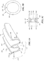
- FIGs. 1A-1C depict graphical representations of a seal according to one or more embodiments.
- the seal 100 has an inner diameter 120, an outer diameter 125, a height 130, and a width 140.
- the seal 100 includes leading edge 105 and trailing edge 106.
- the seal further includes a seal body 101 between the leading edge 105 and the trailing edge 106.
- the seal further includes a plurality of bends 115 1-n disposed between the leading edge 105 and the trailing edge 106.
- the plurality of bends 115 1-n can be any one of a trough, ridge, or other geometric profile.
- the seal body 101 has a cross-sectional shape 102.
- the seal body 101 is formed of a single crystal grain structure, the single crystal grain structure oriented in a single crystal grain structure direction 103 following the cross-sectional shape 102 of the seal body.
- the cross-sectional shape 102 is a two-dimensional shape represented by a cross-section of the seal 100, such that the cross-sectional shape 102 is substantially the same at the first end 110, the second end 120, and a plurality of locations along the seal 100 between the first end 110 and the second end 120.
- the seal 100 also has a single crystal grain structure direction 103, the single crystal grain structure direction 103 directed along the cross-sectional shape 102 such that the single crystal grain structure direction 102 is configured in the same direction as the cross-sectional shape 102.
- the grain structure has one crystal, with a very distinct orientation of atoms.
- the distinct orientation of atoms thus, affects the mechanical properties of the crystalline material.
- a single crystal grain structure direction 103 can affect the stiffness of a crystalline material. Stiffness is also often represented as the Young's modulus of the material.
- the Young's modulus of the material With a single crystal grain structure direction 103, the Young's modulus of the material is reduced. This Young's modulus is dictated by the distinct orientation of the atoms associated with the single crystal grain structure direction 103. For sealing elements, a reduced Young's modulus is desirable; this desirability is described in more detail below with reference to FIG. 2 .
- the material of the seal 100 is a precipitation hardened nickel based super alloy with more than 5% weight aluminum.
- the precipitation nickel based super alloy has more than 50% by volume of the precipitates if aluminum is added in combination with elements such as titanium, tantalum, or nibobium to form the precipitates.
- the maximum exposure temperature is within the range of 1200° F to 2000° F (650°C to 1100°C) .
- FIG. 1 depicts a seal 100 with a cross-sectional shape 102 of a "W," the seal can be of any shape for the application in which it is used.
- the shape of the seal is application-specific.
- the cross-sectional shape 102 of the seal can be an O-shape, a C-shape, a Diamond-shape, a Dogbone-shape, a Feather-shape, a Bathtub-seal shape, a Wire-seal shape, or any other geometric shape.
- first end 110 of the seal 100 may interface with a second end (not shown in FIG. 1A ) of seal 100.
- FIG. 1B depicts a graphical representation of the seal 100 from an axial or perspective view. This view includes the leading edge 105.
- the first end 110 may be joined or fused to a second end 120 in region 145.
- the joining or fusing could be by any common means, such as adhesive, welding, additional mechanical fasteners, or any other common form of joining or fusing.
- one or more joint elements may be employed, as described in more detail below with reference to FIG. 3 .
- FIG. 1C depicts a cut-away representation of the seal 100, when disposed between components, such as components of a gas turbine engine.
- the seal 100 is depicted in two separate orientations.
- the seal 100 is disposed between the first component 150 and the second component 151.
- the seal 100 is in contact with the first component at a first contact point 155.
- the seal 100 is in contact with the second component 151 at a second contact point 160. Contact with the first component 150 and the second component 151 thus forms a complete seal between the two components.
- the seal is designed to fill an existing gap between two components, and the seal would deflect and compress a certain amount. Sealing can be more difficult if either of the two contact points are not oriented such that a uniform gap exists. In other words, the seal might not be "flush" or level between the two contact points. To remedy this problem, a softer or more flexible material is desirable for a seal. A more flexible seal will deflect more, and tolerate a greater range of motion. A more flexible seal will also have a higher endurance, because there is a lower resulting stress in the seal. Another advantage is more translation of the seal before reaching the seal's critical stress.
- the Young's Modulus can be controlled, effectively allowing for seals that can handle more deflection. Furthermore, using a material such as a nickel super alloy for the seal material, with the desired crystalline orientation, can reduce the stresses in the seal. Making the same seal with a standard nickel alloy material, the stresses would be 50% higher. Finally, these seals can have improved wear resistance, oxidation resistance, resistance to creep, and a number of other added benefits.
- a durable and flexible seal is desirable, because the seal will no longer be the limiting component of the apparatus in which the seal is used. For these reasons, it is desirable that a seal properly deals with: high temperature, creep, stress rupture, wear resistance, oxidation resistance, overall compatibility, and coefficient of thermal expansion, among other factors.
- FIG. 2 depicts the deflection of a first seal 200 with a reduced modulus of elasticity.
- the first seal 200 has a first cross-sectional shape 202.
- the first cross-sectional shape 202 is a two-dimensional shape represented by a cross-section of the first seal 200.
- the first seal 200 also has a first crystal grain structure direction 203, which is a single crystal grain structure direction. This first crystal grain structure direction 203 is directed along the first cross-sectional shape 202 such that the first crystal grain structure direction 203 is configured in the same direction as the first cross-sectional shape 202.
- FIG. 2 also depicts the deflection of a second seal 250.
- the second seal 250 has a second cross-sectional shape 252.
- the second cross-sectional shape 252 is a two-dimensional shape represented by a cross-section of the second seal 250.
- the second seal 250 also has a second crystal grain structure direction 253.
- This second crystal grain structure direction 253 is not a single crystal grain structure direction like that of the first seal 202.
- the second crystal grain structure direction 253 is not configured in the same direction as the second cross-sectional shape 252.
- the crystalline material associated with a first seal 202 and a second seal 250 is a nickel super alloy.
- the first seal 202 has a first crystal grain structure direction 203, which is a single crystal grain structure direction.
- the Young's modulus of the material is approximately 18 million pounds-per square inch (PSI) (e.g., 12.4 million Newtons per square centimeter (N/cm 2 ); 124 GPa) in one crystalline direction at room temperature. In other directions, alternatively, the Young's modulus can be higher.
- PSI pounds-per square inch
- N/cm 2 12.4 million Newtons per square centimeter
- the Young's modulus can be approximately 28-32 million PSI (e.g., 19.3 million-22 million N/cm 2 ;193-220 Gpa) at room temperature.
- the Young's modulus in the second crystal grain structure direction 253 can be much higher than the Young's modulus in the first crystal grain structure direction 203.
- both the first seal 202 and the second seal 250 involve the same material, a nickel super alloy. Therefore, different crystalline directions 203/253 can yield different Young's moduli for the same material.
- certain crystalline directions can be "stiffer" than other crystalline directions for the same crystalline material. For a "stiffer" material, with a higher Young's modulus, the material will deflect less. Alternatively, with a lower Young's modulus is, the material will deflect more.
- a component's material characteristics such, as Young's modulus, ductility, wear resistance, and oxidation resistance could reduce the likelihood of creep, thus reducing the likelihood of mechanical failure.
- a component must operate within an overall system. For instance, while strength may be desirable for a material generally, flexibility may also be desirable for the system in which the material is being used. For this reason, an individual component's material characteristics must be optimized.
- One way of optimizing a material's inherent characteristics is to control the crystalline structure of the material. Use of a single crystalline structure, and a desired crystalline orientation, can improve a component's material characteristics within an advanced technology system.
- a lower Young's is often desirable.
- One of a seal's purposes is to contact a surface. If a seal is rigid, it might not form as complete of a seal. Reducing the seal's Young's modulus could allow for a seal to deflect substantially more. In a preferred embodiment, the reduced Young's Modulus due to crystalline orientation would allow for a seal to deflect an additional 25-50%, thus providing a much better seal.
- flexibility and ductility in materials can often mean that the material is "weaker” to external forces. While flexibility is a desirable mechanical property for seals, there are other desirable mechanical properties: such as stability, wear resistance, and oxidation resistance. These other desirable mechanical properties become more and more crucial as the seal is used in components at high temperatures and pressures.
- Titanium has a lower Young's modulus than a nickel super alloy. In other words, Titanium is generally more flexible than a nickel super alloy.
- Titanium reacts with oxygen to produce a brittle scale.
- being able to reduce the Young's modulus of a crystalline material to make the crystalline material more flexible, through the orientation of a crystalline structure in a desired crystalline direction, while simultaneously employing a crystalline material that has other desirable mechanical properties is extremely beneficial for the engineering of high temperature and high pressure systems.
- the seal would no longer be the limiting component of the apparatus. From a wear standpoint, a more wear resistant seal means fewer repairs for the apparatus in which it is used.
- the seal is a W-seal and has a single crystal grain structure direction and a cross-sectional shape that is in the form of a W-shape. Because the W-shape seal has multiple bends along its cross-section, the seal has multiple opportunities for deflection. Varying deflection means there is a varying bending stress throughout in the W-seal's cross-sectional plane. Similar to wood veneer, which easily bends in the direction across the grain, the W-seal is anisotropic in an atomic manner. This atomic manner is dictated by the single crystal grain structure direction of the seal. The result of this is that one direction can bend or deflect more easily, while one direction is stiffer and harder to bend or deflect.
- the seal is a complete circumferential seal. That is, the seal has a first end and a second end, and the first end and the second end contact one another, such that the seal forms a complete circle. In other embodiments, the seal is not a complete circumferential seal, but instead a half-circle, or even a straight piece.
- FIG. 3 depicts a layered split-seal 300.
- the layered split-seal 300 has a first end 310 and a second end 320. The first end 310 and second end 320 do not contact one another. In other words, the layered split-seal 300 does not form a complete circumference.
- the layered split-seal 300 can be layered on top of a second layered split-seal 350. Layering seals can prevent a gap 340 created by an end 360 of a second layered split-seal 350 by covering the gap 340.
- the layered split-seal 300 and the second layered split-seal 350 can be joined or fused.
- the joining or fusing could be by any common means, such as adhesive, welding, additional mechanical fasteners, or any other common form of joining or fusing
- the seal is used to seal a gap between a first component and a second component.
- the first component has a plurality of first sub-components
- the second component has a plurality of second sub-components.
- the first sub-components and second sub-components may not be "flush" with one another. In other words, gaps may exist between the first component and the second component, and between individual first sub-components and individual second sub-components. For this reason, a flexible seal is desirable.
- a flexible seal that provides for deflection will serve as a better sealing element between the first component and the second component.
- the plurality of first sub-components is a plurality of segmented vanes.
- the plurality of second sub-components is a plurality of segmented boas.
- the seal is used to seal a gap between the plurality of segmented vanes and the plurality of segmented boas.
- the W-seal is one of a plurality of seal designs that can be used. The W-seal has a single crystalline direction, along the cross-sectional direction of the seal itself.
- the top side of the W can deflect as the seal is contacted by the surfaces of the plurality of segmented vanes and the plurality of segmented boas. This W-seal allows for an improved sealing of the gap across the components.
- FIG. 4A depicts the use of a seal between a plurality of vanes and an air seal.
- An analysis is done to assess the plurality of anticipated stresses between a first component and a second component.
- the first component is a plurality of segmented vanes 401A/402A and the second component is a plurality of segmented boas 403A.
- the plurality of segmented boas 403A is an air seal.
- the seal 400A including the cross-sectional shape of the seal, is selected based on the plurality of anticipated stresses.
- the seal 400A is oriented in a preferred orientation between the plurality of segmented vanes 401A/402A and the plurality of segmented boas 403A.
- the seal 400A is then inserted into a gap 404A between the plurality of segmented vanes 401A/402A and the plurality of segmented boas 403A. Upon insertion, the seal 400A reduces the ability of a fluid to flow through the gap 404A.
- FIG. 4B depicts a seal deflection to seal a gap.
- the seal 400B is designed to seal a gap 404B between a first vane 401B and a second vane 402B and a secondary component (not pictured).
- the first vane 401B and the second vane 402B are not "flush.” In other words, a gap 404B exists. For this reason, a flexible seal is desirable.
- a flexible seal, such as the seal 400B, which provides for enhanced deflection will serve as a better sealing element for the gap 404B between the first vane 401B and the second vane 402B and a secondary component (not pictured).
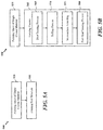
- FIGs. 5A-5B depict processes for forming a seal according to one or more embodiments.
- FIG. 5A depicts process 500 including forming a sheet of single crystal material at block 505.
- this sheet of single crystal material is created by investment casting, using directional solidification.
- the single crystal material is preferably a precipitation hardened nickel based super alloy with more than 5% weight aluminum, or more than 50% by volume of the precipitates if aluminum is added in combination with elements such as titanium, tantalum, or nibobium to form the precipitates.
- the resulting casting preferably has single crystal grain structure direction parallel to the direction of solidification. With particular cross-sections, it is often helpful to seed the casting with a property selected crystal seed.
- a seal structure such as the seal structure described above may be formed.
- the forming process for the thin section of single crystal material can take place in an as-cast, or a heat treated, condition.
- the thin section is mechanically formed, such that the desired seal structure results.
- the thin section is mechanically formed at block 510 such that the cross-sectional shape is a W-shape.
- FIG. 5B depicts a preferred approach for forming a seal.
- the process 550 includes forming a sheet of single crystal material at block 555.
- this sheet of single crystal material is created by investment casting, using directional solidification.
- the single crystal material is preferably a precipitation hardened nickel based super alloy with more than 5% weight aluminum.
- the resulting casting preferably has single crystal grain structure direction parallel to the direction of solidification. With particular cross-sections, it is often helpful to seed the casting with a property selected crystal seed. Use of a seed ensures that the faces of the ingot are also cube directions.
- a seal structure such as the seal structure described above may be formed.
- the forming process 560 requires that the thin section of single crystal material is rolled to be formed. This rolling process reduces the thin section of single crystal material to a desired thickness while simultaneously improving the fatigue response.
- the forming process at block 560 requires that the thin section of single crystal material is solution heat treated and subsequently slow cooled at block 565. This heat treating process allows for a coarsening of precipitates, such that the thin section of single crystal material becomes softer. Such softened material is then rolled at block 570.
- the temperature is controlled such that the temperature of the thin section of single crystal material is below the recrystallization temperature of the alloy.
- this temperature is estimated at approximately 85% of the solution temperature, expressed on an absolute scale.
- the rolling process at block 570 can result in any desired shape for the thin section of single crystal material.
- the forming process at block 560 must take place gradually, to avoid overstressing the thin section of single crystal material. For this reason, the forming process at block 560 could be repeated a number of times before the desired shape is created.
- a number of treating processes may be required within the forming process at block 560. These treating processes could include a pre-heat treatment process at block 565, intermediate annealing treatment after the rolling process at block 575, and a post-heat treatment at block 580.
- the single crystal ingot could be spiral cast and subsequently spiral cut to length.
- the thin section of single crystal material undergoes the rolling process at block 570 such that the resulting desired shape is a W-shape.
- a single crystal grain structure direction is in the shape of the "W.”
- the crystal would follow curvature of the "W,” along the cross-sectional shape of the seal, such that the single crystal grain structure follows the W-profile.
- the entire "W” would be in a single crystal grain structure direction.
- the sheet can be rolled at block 570 such that the cross-sectional shape of the seal can be an O-shape, a C-shape, a Diamond-shape, a Dogbone-shape, a Feather-shape, a Bathtub-seal shape, a Wire-seal shape, or any other geometric shape.
- the rolling process can create any shape for the individual application in which the seal is being used.
Landscapes
- Engineering & Computer Science (AREA)
- Chemical & Material Sciences (AREA)
- General Engineering & Computer Science (AREA)
- Mechanical Engineering (AREA)
- Crystallography & Structural Chemistry (AREA)
- Materials Engineering (AREA)
- Metallurgy (AREA)
- Organic Chemistry (AREA)
- Inorganic Chemistry (AREA)
- Gasket Seals (AREA)
- Turbine Rotor Nozzle Sealing (AREA)
Applications Claiming Priority (1)
| Application Number | Priority Date | Filing Date | Title |
|---|---|---|---|
| US14/695,981 US10830357B2 (en) | 2015-04-24 | 2015-04-24 | Single crystal grain structure seals and method of forming |
Publications (2)
| Publication Number | Publication Date |
|---|---|
| EP3085902A1 true EP3085902A1 (fr) | 2016-10-26 |
| EP3085902B1 EP3085902B1 (fr) | 2019-07-03 |
Family
ID=56148062
Family Applications (1)
| Application Number | Title | Priority Date | Filing Date |
|---|---|---|---|
| EP16166894.2A Active EP3085902B1 (fr) | 2015-04-24 | 2016-04-25 | Structure de grain monocristallin et procédé de formation de joints d'étanchéité |
Country Status (2)
| Country | Link |
|---|---|
| US (1) | US10830357B2 (fr) |
| EP (1) | EP3085902B1 (fr) |
Cited By (3)
| Publication number | Priority date | Publication date | Assignee | Title |
|---|---|---|---|---|
| EP3196322A1 (fr) * | 2016-01-22 | 2017-07-26 | United Technologies Corporation | Joint mince pour une turbine à gaz |
| EP3470633A1 (fr) * | 2017-10-11 | 2019-04-17 | United Technologies Corporation | Joint de piston résistant à l'usure |
| US11643939B2 (en) | 2020-09-02 | 2023-05-09 | Raytheon Technologies Corporation | Seals and methods of making seals |
Families Citing this family (19)
| Publication number | Priority date | Publication date | Assignee | Title |
|---|---|---|---|---|
| US11181002B2 (en) * | 2016-09-29 | 2021-11-23 | General Electric Company | Turbine systems with sealing components |
| US11208907B2 (en) * | 2017-07-13 | 2021-12-28 | Raytheon Technologies Corporation | Seals and methods of making seals |
| US11459899B2 (en) | 2018-03-23 | 2022-10-04 | Raytheon Technologies Corporation | Turbine component with a thin interior partition |
| US12286906B1 (en) | 2023-12-04 | 2025-04-29 | Rolls-Royce Corporation | Locating plate for use with turbine shroud assemblies |
| US12241376B1 (en) | 2023-12-04 | 2025-03-04 | Rolls-Royce Corporation | Locating plate for use with turbine shroud assemblies |
| US12286885B1 (en) | 2023-12-04 | 2025-04-29 | Rolls-Royce Corporation | Turbine assembly with confronting vane and turbine shroud segment |
| US12158072B1 (en) | 2023-12-04 | 2024-12-03 | Rolls-Royce Corporation | Turbine shroud segments with damping strip seals |
| US12421862B2 (en) | 2023-12-04 | 2025-09-23 | Rolls-Royce Corporation | Turbine shroud assembly with angled cooling holes |
| US12152499B1 (en) | 2023-12-04 | 2024-11-26 | Rolls-Royce Corporation | Turbine shroud segments with strip seal assemblies having dampened ends |
| US12188365B1 (en) | 2023-12-04 | 2025-01-07 | Rolls-Royce Corporation | Method and apparatus for ceramic matrix composite turbine shroud assembly |
| US12421870B1 (en) | 2024-04-30 | 2025-09-23 | Rolls-Royce Corporation | Pin mounted ceramic matrix composite heat shields with impingement cooling |
| US12215593B1 (en) | 2024-05-30 | 2025-02-04 | Rolls-Royce Corporation | Turbine shroud assembly with inter-segment damping |
| US12416241B1 (en) | 2024-05-30 | 2025-09-16 | Rolls-Royce Corporation | Turbine shroud assemblies with strip seals |
| US12305525B1 (en) | 2024-05-30 | 2025-05-20 | Rolls-Royce Corporation | Turbine shroud assemblies with rod seal and strip seals |
| US12258880B1 (en) | 2024-05-30 | 2025-03-25 | Rolls-Royce Corporation | Turbine shroud assemblies with inter-segment strip seal |
| US12352176B1 (en) | 2024-05-31 | 2025-07-08 | Rolls-Royce Corporation | Turbine shroud assemblies with channels for buffer cavity seal thermal management |
| US12410725B1 (en) | 2024-05-31 | 2025-09-09 | Rolls-Royce Corporation | Turbine shroud assemblies with air activated pistons for biasing buffer cavity seals |
| US12577881B2 (en) | 2024-05-31 | 2026-03-17 | Rolls-Royce Corporation | Turbine shroud assemblies with anti-migration seals |
| US12228044B1 (en) | 2024-06-26 | 2025-02-18 | Rolls-Royce Corporation | Turbine shroud system with ceramic matrix composite segments and dual inter-segment seals |
Citations (4)
| Publication number | Priority date | Publication date | Assignee | Title |
|---|---|---|---|---|
| EP0475428A1 (fr) * | 1990-09-14 | 1992-03-18 | Hitachi, Ltd. | Turbine à gaz, aube pour cette turbine à gaz et méthode de fabriction de l'aube |
| EP1593757A1 (fr) * | 2004-05-06 | 2005-11-09 | United Technologies Corporation | Membres céramiques/métalliques integrés et méthodes pour leurs fabrication |
| EP1878873A2 (fr) * | 2006-07-13 | 2008-01-16 | United Technologies Corporation | Alliages de moteurs à turbines et orientations cristallines |
| WO2015089431A1 (fr) * | 2013-12-12 | 2015-06-18 | United Technologies Corporation | Joint à air extérieur de pale avec jointement d'air secondaire |
Family Cites Families (15)
| Publication number | Priority date | Publication date | Assignee | Title |
|---|---|---|---|---|
| US3572734A (en) * | 1968-09-27 | 1971-03-30 | John E Holt | Shaft seal |
| DE2305722C2 (de) * | 1973-02-06 | 1983-11-03 | Kabushiki Kaisha Komatsu Seisakusho, Tokyo | Abdichtung von Kettenbolzen bei Gleisketten |
| GB2189850A (en) * | 1986-05-02 | 1987-11-04 | Michael John Caswell Tozer | Metallic sealing rings |
| US6199871B1 (en) * | 1998-09-02 | 2001-03-13 | General Electric Company | High excursion ring seal |
| JP4577813B2 (ja) * | 2003-08-20 | 2010-11-10 | イーグル・エンジニアリング・エアロスペース株式会社 | シール装置 |
| JP4322600B2 (ja) * | 2003-09-02 | 2009-09-02 | イーグル・エンジニアリング・エアロスペース株式会社 | シール装置 |
| WO2005119104A1 (fr) * | 2003-11-04 | 2005-12-15 | Advanced Components & Materials, Inc. | Joints a ressorts haute temperature |
| US7938407B2 (en) * | 2003-11-04 | 2011-05-10 | Parker-Hannifin Corporation | High temperature spring seals |
| EP1953802A3 (fr) * | 2007-02-01 | 2012-05-23 | Parker-Hannifin Corporation | Chambre de procédés pour semiconducteur |
| US20100072710A1 (en) * | 2008-09-22 | 2010-03-25 | General Electric Company | Gas Turbine Seal |
| US8827642B2 (en) * | 2011-01-31 | 2014-09-09 | General Electric Company | Flexible seal for turbine engine |
| US20120235366A1 (en) * | 2011-03-15 | 2012-09-20 | General Electric Company | Seal for turbine engine bucket |
| US20130113168A1 (en) * | 2011-11-04 | 2013-05-09 | Paul M. Lutjen | Metal gasket for a gas turbine engine |
| US9719363B2 (en) * | 2014-06-06 | 2017-08-01 | United Technologies Corporation | Segmented rim seal spacer for a gas turbine engine |
| US20160003078A1 (en) * | 2014-07-02 | 2016-01-07 | United Technologies Corporation | Gasket with thermal and wear protective fabric |
-
2015
- 2015-04-24 US US14/695,981 patent/US10830357B2/en active Active
-
2016
- 2016-04-25 EP EP16166894.2A patent/EP3085902B1/fr active Active
Patent Citations (4)
| Publication number | Priority date | Publication date | Assignee | Title |
|---|---|---|---|---|
| EP0475428A1 (fr) * | 1990-09-14 | 1992-03-18 | Hitachi, Ltd. | Turbine à gaz, aube pour cette turbine à gaz et méthode de fabriction de l'aube |
| EP1593757A1 (fr) * | 2004-05-06 | 2005-11-09 | United Technologies Corporation | Membres céramiques/métalliques integrés et méthodes pour leurs fabrication |
| EP1878873A2 (fr) * | 2006-07-13 | 2008-01-16 | United Technologies Corporation | Alliages de moteurs à turbines et orientations cristallines |
| WO2015089431A1 (fr) * | 2013-12-12 | 2015-06-18 | United Technologies Corporation | Joint à air extérieur de pale avec jointement d'air secondaire |
Cited By (3)
| Publication number | Priority date | Publication date | Assignee | Title |
|---|---|---|---|---|
| EP3196322A1 (fr) * | 2016-01-22 | 2017-07-26 | United Technologies Corporation | Joint mince pour une turbine à gaz |
| EP3470633A1 (fr) * | 2017-10-11 | 2019-04-17 | United Technologies Corporation | Joint de piston résistant à l'usure |
| US11643939B2 (en) | 2020-09-02 | 2023-05-09 | Raytheon Technologies Corporation | Seals and methods of making seals |
Also Published As
| Publication number | Publication date |
|---|---|
| US10830357B2 (en) | 2020-11-10 |
| US20160312894A1 (en) | 2016-10-27 |
| EP3085902B1 (fr) | 2019-07-03 |
Similar Documents
| Publication | Publication Date | Title |
|---|---|---|
| EP3085902B1 (fr) | Structure de grain monocristallin et procédé de formation de joints d'étanchéité | |
| US7938407B2 (en) | High temperature spring seals | |
| US7464940B2 (en) | High temperature spring seals | |
| EP2963135B1 (fr) | Procédé de fabrication d'un superalliage à base de ni et élément de superalliage à base de ni, superalliage à base de ni, élément de superalliage à base de ni, billette forgée de superalliage à base de ni, composant de superalliage à base de ni, structure de superalliage à base de ni, tube de chaudière, chemise de chambre de combustion, aube de turbine à gaz et disque de turbine à gaz | |
| EP2634275B1 (fr) | Alliage de cuivre résistant à la pression et à la corrosion, structure brasée et procédé pour la production de la structure brasée | |
| EP3149216B1 (fr) | Alliages de nickel monocristallin pouvant être très facilement traités | |
| EP2679333A1 (fr) | Procédé de fabrication d'une hélice | |
| US20040239053A1 (en) | Seal | |
| WO2021024687A1 (fr) | Procédé de liaison par diffusion de matériaux dissemblables, et structure liée par diffusion de matériaux dissemblables | |
| JP6792837B2 (ja) | チタン‐アルミニウム合金 | |
| EP2210683A1 (fr) | Articles avec structure interne | |
| WO2018034284A1 (fr) | Alliage de cuivre facilement usinable et procédé de fabrication de celui-ci | |
| EP2189548B1 (fr) | Matériau amortissant les contraintes | |
| EP2243626B1 (fr) | Procédé de fabrication d'une surface portante | |
| DE60218800T2 (de) | Hochtemperaturdichtung | |
| EP3752699B1 (fr) | Pilier compressible pour unité de vitrage isolé sous vide | |
| EP1721998B1 (fr) | Matériau tubulaire extrudé en alliage d'aluminium pour échangeur de chaleur avec réfrigérant naturel | |
| FI129766B (en) | Dual alloy pyrotechnic useful valve assembly | |
| US20190143396A1 (en) | Core for high-temperature shaping of a metal part and manufacturing process | |
| EP2003224A1 (fr) | Traitement secondaire de structures dérivées d'alliages AI-RE-TM | |
| EP3597917A1 (fr) | Revêtement d'alliage à mémoire de forme utilisant la fabrication additive | |
| US11835158B2 (en) | Mechanical joining of Nitinol tubes | |
| Roder et al. | Microstructure and mechanical properties of an inertia friction welded INCOLOY alloy 909–INCONEL alloy 718 joint for rotating applications | |
| US20140325823A1 (en) | Method for assembling a titanium shell with a titanium fire resistant alloy shell | |
| JP6756283B2 (ja) | 円筒型スパッタリングターゲット |
Legal Events
| Date | Code | Title | Description |
|---|---|---|---|
| PUAI | Public reference made under article 153(3) epc to a published international application that has entered the european phase |
Free format text: ORIGINAL CODE: 0009012 |
|
| AK | Designated contracting states |
Kind code of ref document: A1 Designated state(s): AL AT BE BG CH CY CZ DE DK EE ES FI FR GB GR HR HU IE IS IT LI LT LU LV MC MK MT NL NO PL PT RO RS SE SI SK SM TR |
|
| AX | Request for extension of the european patent |
Extension state: BA ME |
|
| 17P | Request for examination filed |
Effective date: 20170426 |
|
| RBV | Designated contracting states (corrected) |
Designated state(s): AL AT BE BG CH CY CZ DE DK EE ES FI FR GB GR HR HU IE IS IT LI LT LU LV MC MK MT NL NO PL PT RO RS SE SI SK SM TR |
|
| STAA | Information on the status of an ep patent application or granted ep patent |
Free format text: STATUS: REQUEST FOR EXAMINATION WAS MADE |
|
| STAA | Information on the status of an ep patent application or granted ep patent |
Free format text: STATUS: EXAMINATION IS IN PROGRESS |
|
| 17Q | First examination report despatched |
Effective date: 20180309 |
|
| GRAP | Despatch of communication of intention to grant a patent |
Free format text: ORIGINAL CODE: EPIDOSNIGR1 |
|
| STAA | Information on the status of an ep patent application or granted ep patent |
Free format text: STATUS: GRANT OF PATENT IS INTENDED |
|
| INTG | Intention to grant announced |
Effective date: 20190108 |
|
| GRAS | Grant fee paid |
Free format text: ORIGINAL CODE: EPIDOSNIGR3 |
|
| GRAA | (expected) grant |
Free format text: ORIGINAL CODE: 0009210 |
|
| STAA | Information on the status of an ep patent application or granted ep patent |
Free format text: STATUS: THE PATENT HAS BEEN GRANTED |
|
| AK | Designated contracting states |
Kind code of ref document: B1 Designated state(s): AL AT BE BG CH CY CZ DE DK EE ES FI FR GB GR HR HU IE IS IT LI LT LU LV MC MK MT NL NO PL PT RO RS SE SI SK SM TR |
|
| REG | Reference to a national code |
Ref country code: GB Ref legal event code: FG4D |
|
| REG | Reference to a national code |
Ref country code: CH Ref legal event code: EP Ref country code: AT Ref legal event code: REF Ref document number: 1151235 Country of ref document: AT Kind code of ref document: T Effective date: 20190715 |
|
| REG | Reference to a national code |
Ref country code: DE Ref legal event code: R096 Ref document number: 602016016133 Country of ref document: DE |
|
| REG | Reference to a national code |
Ref country code: IE Ref legal event code: FG4D |
|
| REG | Reference to a national code |
Ref country code: NL Ref legal event code: MP Effective date: 20190703 |
|
| REG | Reference to a national code |
Ref country code: LT Ref legal event code: MG4D |
|
| REG | Reference to a national code |
Ref country code: AT Ref legal event code: MK05 Ref document number: 1151235 Country of ref document: AT Kind code of ref document: T Effective date: 20190703 |
|
| PG25 | Lapsed in a contracting state [announced via postgrant information from national office to epo] |
Ref country code: BG Free format text: LAPSE BECAUSE OF FAILURE TO SUBMIT A TRANSLATION OF THE DESCRIPTION OR TO PAY THE FEE WITHIN THE PRESCRIBED TIME-LIMIT Effective date: 20191003 Ref country code: NO Free format text: LAPSE BECAUSE OF FAILURE TO SUBMIT A TRANSLATION OF THE DESCRIPTION OR TO PAY THE FEE WITHIN THE PRESCRIBED TIME-LIMIT Effective date: 20191003 Ref country code: SE Free format text: LAPSE BECAUSE OF FAILURE TO SUBMIT A TRANSLATION OF THE DESCRIPTION OR TO PAY THE FEE WITHIN THE PRESCRIBED TIME-LIMIT Effective date: 20190703 Ref country code: PT Free format text: LAPSE BECAUSE OF FAILURE TO SUBMIT A TRANSLATION OF THE DESCRIPTION OR TO PAY THE FEE WITHIN THE PRESCRIBED TIME-LIMIT Effective date: 20191104 Ref country code: NL Free format text: LAPSE BECAUSE OF FAILURE TO SUBMIT A TRANSLATION OF THE DESCRIPTION OR TO PAY THE FEE WITHIN THE PRESCRIBED TIME-LIMIT Effective date: 20190703 Ref country code: AT Free format text: LAPSE BECAUSE OF FAILURE TO SUBMIT A TRANSLATION OF THE DESCRIPTION OR TO PAY THE FEE WITHIN THE PRESCRIBED TIME-LIMIT Effective date: 20190703 Ref country code: CZ Free format text: LAPSE BECAUSE OF FAILURE TO SUBMIT A TRANSLATION OF THE DESCRIPTION OR TO PAY THE FEE WITHIN THE PRESCRIBED TIME-LIMIT Effective date: 20190703 Ref country code: FI Free format text: LAPSE BECAUSE OF FAILURE TO SUBMIT A TRANSLATION OF THE DESCRIPTION OR TO PAY THE FEE WITHIN THE PRESCRIBED TIME-LIMIT Effective date: 20190703 Ref country code: LT Free format text: LAPSE BECAUSE OF FAILURE TO SUBMIT A TRANSLATION OF THE DESCRIPTION OR TO PAY THE FEE WITHIN THE PRESCRIBED TIME-LIMIT Effective date: 20190703 Ref country code: HR Free format text: LAPSE BECAUSE OF FAILURE TO SUBMIT A TRANSLATION OF THE DESCRIPTION OR TO PAY THE FEE WITHIN THE PRESCRIBED TIME-LIMIT Effective date: 20190703 |
|
| PG25 | Lapsed in a contracting state [announced via postgrant information from national office to epo] |
Ref country code: GR Free format text: LAPSE BECAUSE OF FAILURE TO SUBMIT A TRANSLATION OF THE DESCRIPTION OR TO PAY THE FEE WITHIN THE PRESCRIBED TIME-LIMIT Effective date: 20191004 Ref country code: LV Free format text: LAPSE BECAUSE OF FAILURE TO SUBMIT A TRANSLATION OF THE DESCRIPTION OR TO PAY THE FEE WITHIN THE PRESCRIBED TIME-LIMIT Effective date: 20190703 Ref country code: IS Free format text: LAPSE BECAUSE OF FAILURE TO SUBMIT A TRANSLATION OF THE DESCRIPTION OR TO PAY THE FEE WITHIN THE PRESCRIBED TIME-LIMIT Effective date: 20191103 Ref country code: AL Free format text: LAPSE BECAUSE OF FAILURE TO SUBMIT A TRANSLATION OF THE DESCRIPTION OR TO PAY THE FEE WITHIN THE PRESCRIBED TIME-LIMIT Effective date: 20190703 Ref country code: RS Free format text: LAPSE BECAUSE OF FAILURE TO SUBMIT A TRANSLATION OF THE DESCRIPTION OR TO PAY THE FEE WITHIN THE PRESCRIBED TIME-LIMIT Effective date: 20190703 Ref country code: ES Free format text: LAPSE BECAUSE OF FAILURE TO SUBMIT A TRANSLATION OF THE DESCRIPTION OR TO PAY THE FEE WITHIN THE PRESCRIBED TIME-LIMIT Effective date: 20190703 |
|
| PG25 | Lapsed in a contracting state [announced via postgrant information from national office to epo] |
Ref country code: TR Free format text: LAPSE BECAUSE OF FAILURE TO SUBMIT A TRANSLATION OF THE DESCRIPTION OR TO PAY THE FEE WITHIN THE PRESCRIBED TIME-LIMIT Effective date: 20190703 |
|
| PG25 | Lapsed in a contracting state [announced via postgrant information from national office to epo] |
Ref country code: DK Free format text: LAPSE BECAUSE OF FAILURE TO SUBMIT A TRANSLATION OF THE DESCRIPTION OR TO PAY THE FEE WITHIN THE PRESCRIBED TIME-LIMIT Effective date: 20190703 Ref country code: EE Free format text: LAPSE BECAUSE OF FAILURE TO SUBMIT A TRANSLATION OF THE DESCRIPTION OR TO PAY THE FEE WITHIN THE PRESCRIBED TIME-LIMIT Effective date: 20190703 Ref country code: PL Free format text: LAPSE BECAUSE OF FAILURE TO SUBMIT A TRANSLATION OF THE DESCRIPTION OR TO PAY THE FEE WITHIN THE PRESCRIBED TIME-LIMIT Effective date: 20190703 Ref country code: IT Free format text: LAPSE BECAUSE OF FAILURE TO SUBMIT A TRANSLATION OF THE DESCRIPTION OR TO PAY THE FEE WITHIN THE PRESCRIBED TIME-LIMIT Effective date: 20190703 Ref country code: RO Free format text: LAPSE BECAUSE OF FAILURE TO SUBMIT A TRANSLATION OF THE DESCRIPTION OR TO PAY THE FEE WITHIN THE PRESCRIBED TIME-LIMIT Effective date: 20190703 |
|
| PG25 | Lapsed in a contracting state [announced via postgrant information from national office to epo] |
Ref country code: SK Free format text: LAPSE BECAUSE OF FAILURE TO SUBMIT A TRANSLATION OF THE DESCRIPTION OR TO PAY THE FEE WITHIN THE PRESCRIBED TIME-LIMIT Effective date: 20190703 Ref country code: IS Free format text: LAPSE BECAUSE OF FAILURE TO SUBMIT A TRANSLATION OF THE DESCRIPTION OR TO PAY THE FEE WITHIN THE PRESCRIBED TIME-LIMIT Effective date: 20200224 Ref country code: SM Free format text: LAPSE BECAUSE OF FAILURE TO SUBMIT A TRANSLATION OF THE DESCRIPTION OR TO PAY THE FEE WITHIN THE PRESCRIBED TIME-LIMIT Effective date: 20190703 |
|
| REG | Reference to a national code |
Ref country code: DE Ref legal event code: R097 Ref document number: 602016016133 Country of ref document: DE |
|
| PLBE | No opposition filed within time limit |
Free format text: ORIGINAL CODE: 0009261 |
|
| STAA | Information on the status of an ep patent application or granted ep patent |
Free format text: STATUS: NO OPPOSITION FILED WITHIN TIME LIMIT |
|
| PG2D | Information on lapse in contracting state deleted |
Ref country code: IS |
|
| 26N | No opposition filed |
Effective date: 20200603 |
|
| PG25 | Lapsed in a contracting state [announced via postgrant information from national office to epo] |
Ref country code: SI Free format text: LAPSE BECAUSE OF FAILURE TO SUBMIT A TRANSLATION OF THE DESCRIPTION OR TO PAY THE FEE WITHIN THE PRESCRIBED TIME-LIMIT Effective date: 20190703 |
|
| PG25 | Lapsed in a contracting state [announced via postgrant information from national office to epo] |
Ref country code: MC Free format text: LAPSE BECAUSE OF FAILURE TO SUBMIT A TRANSLATION OF THE DESCRIPTION OR TO PAY THE FEE WITHIN THE PRESCRIBED TIME-LIMIT Effective date: 20190703 |
|
| REG | Reference to a national code |
Ref country code: CH Ref legal event code: PL |
|
| PG25 | Lapsed in a contracting state [announced via postgrant information from national office to epo] |
Ref country code: LI Free format text: LAPSE BECAUSE OF NON-PAYMENT OF DUE FEES Effective date: 20200430 Ref country code: CH Free format text: LAPSE BECAUSE OF NON-PAYMENT OF DUE FEES Effective date: 20200430 Ref country code: LU Free format text: LAPSE BECAUSE OF NON-PAYMENT OF DUE FEES Effective date: 20200425 |
|
| REG | Reference to a national code |
Ref country code: BE Ref legal event code: MM Effective date: 20200430 |
|
| PG25 | Lapsed in a contracting state [announced via postgrant information from national office to epo] |
Ref country code: BE Free format text: LAPSE BECAUSE OF NON-PAYMENT OF DUE FEES Effective date: 20200430 |
|
| PG25 | Lapsed in a contracting state [announced via postgrant information from national office to epo] |
Ref country code: IE Free format text: LAPSE BECAUSE OF NON-PAYMENT OF DUE FEES Effective date: 20200425 |
|
| PG25 | Lapsed in a contracting state [announced via postgrant information from national office to epo] |
Ref country code: MT Free format text: LAPSE BECAUSE OF FAILURE TO SUBMIT A TRANSLATION OF THE DESCRIPTION OR TO PAY THE FEE WITHIN THE PRESCRIBED TIME-LIMIT Effective date: 20190703 Ref country code: CY Free format text: LAPSE BECAUSE OF FAILURE TO SUBMIT A TRANSLATION OF THE DESCRIPTION OR TO PAY THE FEE WITHIN THE PRESCRIBED TIME-LIMIT Effective date: 20190703 |
|
| PG25 | Lapsed in a contracting state [announced via postgrant information from national office to epo] |
Ref country code: MK Free format text: LAPSE BECAUSE OF FAILURE TO SUBMIT A TRANSLATION OF THE DESCRIPTION OR TO PAY THE FEE WITHIN THE PRESCRIBED TIME-LIMIT Effective date: 20190703 |
|
| REG | Reference to a national code |
Ref country code: DE Ref legal event code: R081 Ref document number: 602016016133 Country of ref document: DE Owner name: RAYTHEON TECHNOLOGIES CORPORATION (N.D.GES.D.S, US Free format text: FORMER OWNER: UNITED TECHNOLOGIES CORPORATION, FARMINGTON, CONN., US Ref country code: DE Ref legal event code: R081 Ref document number: 602016016133 Country of ref document: DE Owner name: RTX CORPORATION (N.D.GES.D. STAATES DELAWARE),, US Free format text: FORMER OWNER: UNITED TECHNOLOGIES CORPORATION, FARMINGTON, CONN., US |
|
| P01 | Opt-out of the competence of the unified patent court (upc) registered |
Effective date: 20230520 |
|
| PGFP | Annual fee paid to national office [announced via postgrant information from national office to epo] |
Ref country code: DE Payment date: 20250319 Year of fee payment: 10 |
|
| REG | Reference to a national code |
Ref country code: DE Ref legal event code: R081 Ref document number: 602016016133 Country of ref document: DE Owner name: RTX CORPORATION (N.D.GES.D. STAATES DELAWARE),, US Free format text: FORMER OWNER: RAYTHEON TECHNOLOGIES CORPORATION (N.D.GES.D.STAATES DELAWARE), ARLINGTON, VA, US |
|
| PGFP | Annual fee paid to national office [announced via postgrant information from national office to epo] |
Ref country code: GB Payment date: 20260319 Year of fee payment: 11 |
|
| PGFP | Annual fee paid to national office [announced via postgrant information from national office to epo] |
Ref country code: FR Payment date: 20260320 Year of fee payment: 11 |