EP1879307A1 - Procédé et dispositif pour protéger une liaison de réseau - Google Patents
Procédé et dispositif pour protéger une liaison de réseau Download PDFInfo
- Publication number
- EP1879307A1 EP1879307A1 EP06300793A EP06300793A EP1879307A1 EP 1879307 A1 EP1879307 A1 EP 1879307A1 EP 06300793 A EP06300793 A EP 06300793A EP 06300793 A EP06300793 A EP 06300793A EP 1879307 A1 EP1879307 A1 EP 1879307A1
- Authority
- EP
- European Patent Office
- Prior art keywords
- optical
- fiber link
- network element
- signal
- state
- Prior art date
- Legal status (The legal status is an assumption and is not a legal conclusion. Google has not performed a legal analysis and makes no representation as to the accuracy of the status listed.)
- Granted
Links
- 238000000034 method Methods 0.000 title claims description 6
- 239000000835 fiber Substances 0.000 claims abstract description 83
- 230000003287 optical effect Effects 0.000 claims abstract description 79
- 238000001514 detection method Methods 0.000 claims abstract description 5
- 230000010287 polarization Effects 0.000 claims description 32
- 230000005540 biological transmission Effects 0.000 claims description 7
- 239000013307 optical fiber Substances 0.000 claims description 7
- 230000008859 change Effects 0.000 description 4
- 230000011664 signaling Effects 0.000 description 4
- 230000008054 signal transmission Effects 0.000 description 3
- 230000002457 bidirectional effect Effects 0.000 description 2
- RGNPBRKPHBKNKX-UHFFFAOYSA-N hexaflumuron Chemical compound C1=C(Cl)C(OC(F)(F)C(F)F)=C(Cl)C=C1NC(=O)NC(=O)C1=C(F)C=CC=C1F RGNPBRKPHBKNKX-UHFFFAOYSA-N 0.000 description 2
- 230000007257 malfunction Effects 0.000 description 2
- 239000011159 matrix material Substances 0.000 description 2
- 238000012544 monitoring process Methods 0.000 description 2
- 230000009471 action Effects 0.000 description 1
- 230000008901 benefit Effects 0.000 description 1
- 150000001875 compounds Chemical class 0.000 description 1
- 230000008878 coupling Effects 0.000 description 1
- 238000010168 coupling process Methods 0.000 description 1
- 238000005859 coupling reaction Methods 0.000 description 1
- 230000017525 heat dissipation Effects 0.000 description 1
- 238000012986 modification Methods 0.000 description 1
- 230000004048 modification Effects 0.000 description 1
- 230000006855 networking Effects 0.000 description 1
- 238000000926 separation method Methods 0.000 description 1
- 230000003595 spectral effect Effects 0.000 description 1
Images


Classifications
-
- H—ELECTRICITY
- H04—ELECTRIC COMMUNICATION TECHNIQUE
- H04J—MULTIPLEX COMMUNICATION
- H04J14/00—Optical multiplex systems
- H04J14/02—Wavelength-division multiplex systems
- H04J14/0287—Protection in WDM systems
- H04J14/0289—Optical multiplex section protection
- H04J14/0291—Shared protection at the optical multiplex section (1:1, n:m)
-
- H—ELECTRICITY
- H04—ELECTRIC COMMUNICATION TECHNIQUE
- H04B—TRANSMISSION
- H04B10/00—Transmission systems employing electromagnetic waves other than radio-waves, e.g. infrared, visible or ultraviolet light, or employing corpuscular radiation, e.g. quantum communication
- H04B10/03—Arrangements for fault recovery
- H04B10/032—Arrangements for fault recovery using working and protection systems
-
- H—ELECTRICITY
- H04—ELECTRIC COMMUNICATION TECHNIQUE
- H04J—MULTIPLEX COMMUNICATION
- H04J14/00—Optical multiplex systems
- H04J14/02—Wavelength-division multiplex systems
- H04J14/0278—WDM optical network architectures
- H04J14/0279—WDM point-to-point architectures
Definitions
- the present invention relates to the field of telecommunications and more particularly to an apparatus and related method for protecting an optical fiber link in a transmission network.
- protection In transmission networking, the term protection generally refers to the capability to automatically switch from a working resource to a redundant (protection) resource in the case of a failure.
- 1+1 line protection which is the most common case of protection in transmission networks, means that for each working connection a dedicated protection connection is provided.
- a protected signal is broadcasted at two ports over two fibers in parallel.
- the receiver side can simply switch to receive the protected signal from the protection link. This requires, however, an optical protection switch, which represents an unprotected potential malfunction source (i.e. unreliable), or consumes additional I/O ports and matrix capacity (i.e. costly) if protection switching is performed in the switch matrices of the terminating network elements.
- a network element having at least one optical transmitter for transmitting a protected optical signal.
- the transmitter is tunable with respect to at least one optical property of its output signal and is connected to an input of a passive optical device capable of directing optical signals of a first state or first value range of the optical property to a first output connectable to a working fiber link and of directing optical signals of a second state or second value range of the optical property to a second output connectable to a protection fiber link.
- the network element further has a control device that tunes the transmitter from the first state or first value range of the optical property to the second state or second value range upon detection of a failure.
- the tunable optical property of the optical transmitter can be for instance the wavelength or the polarization of the optical output signal.
- the passive optical element is either a wavelength filter or a polarization filter.
- a passive optical element has a by far higher reliability of maybe a factor 100 than an active protection switch. On the other hand, it requires only about half the costs or doubles capacity as compared to a protection solution that uses separate I/O interfaces and performs switch-over in a switch matrix of the terminating network elements.
- Another particular advantage is that with the present invention power consumption and heat dissipation is drastically reduced as compared to classical protection arrangements, since no additional power is necessary to power the protection connection.
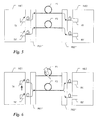
- a basic implementation of the present invention is shown as a first embodiment in figures 1 and 2.
- a first and a second network element NE1, NE2 are interconnected by a working fiber F1 and a protection fiber F2.
- Network element NE1 has a transmitter TX and network element NE2 has a receiver RX. It should be noted that both network elements NE1, NE2 can have and typically have further transmitters and receivers, which are not important for the understanding of the invention and are therefore not shown in figures 1 and 2 for the sake of clarity.
- Network element NE1 contains a first passive protection box PB1 and network element NE2 contains a second passive protection box PB2, the function of which will be described below.
- Passive protection box PB1 has an input which is connected to transmitter TX and two outputs connected to the active fiber and to the protection fiber, respectively.
- protection box PB2 has an optical output connected to the receiver RX and two inputs connected to the active fiber and to the protection fiber, respectively. It should be noted that both protection boxes can have a typically have a number of further inputs and outputs connected to various other external fibers and internal receivers and transmitter, but which are not important for the understanding of the invention and are therefore not shown in figures 1 and 2 for the sake of clarity. Alternatively, there could also be provided a plurality of discrete passive protection boxes instead of one compound box.
- Transmitter TX of network element NE1 is tunable with respect to an optical signal property.
- signal property can be for example the polarization or the wavelength of the output signal.
- the passive optical protection box PB1 is provided to direct a protected output signal in dependence of its tunable optical signal property to either of the working and protection fibers.
- Protection box PB2 collects the protected signal from either the active or protection fiber and feeds it to receiver RX of receive end network element NE2. Since the protection box is a merely passive optical component, it is not prone to failures and hence has a very high reliability.
- the transmitter TX is tunable with respect to the polarization of the output signal. This can be achieved using a simple laser that emits non-polarized signals and a controllable polarization filter. Accordingly, protection box PB1 contains a polarization filter with two outputs for optical signals with mutually orthogonal polarization state.
- the transmitter TX is simply tuned by a corresponding controller (not shown) to change its polarization state, for example from a horizontally polarized signal state to a vertically polarized signal state.
- the polarization filter in protection box PB1 directs signals of horizontal polarization to the working fiber and signals of vertical polarization to the protection fiber.
- Such polarization filter with two outputs can be implemented using a polarization dependant splitter or a branched waveguide with two simple mutually orthogonal polarization filters.
- Figure 1 shows signal flow from network element NE1 to network element NE2 during failure free operation. Signal flow is over the working fiber F1. In figure 2, a fiber breakage has occurred on the working fiber F1. Hence transmitter TX is tuned (indicated by a bold arrow below transmitter TX) to the orthogonal polarization state and signal flow hence is directed over the protection fiber F2.
- a failure once detected at NE2 can be communicated to NE1 using a protection protocol such as K1/K2 signaling in SDH/SONET or similar protocol or can be communicated via a central or distributed control plane.
- a protection protocol such as K1/K2 signaling in SDH/SONET or similar protocol or can be communicated via a central or distributed control plane.
- circular polarization can equally be applied to distinguish and redirect the output signal in the protection case using appropriate polarization filters in the passive protection box PB1.
- receive side protection box PB2 The purpose of receive side protection box PB2 is simply to couple the two fibers F1, F2 to the receiver RX, which can be achieved through a simple optical coupler, irrespective of the polarization state of the received signal. Polarization independent operation at the receive end is preferred in the first embodiment, since polarization is typically not maintained over a long fiber distance.
- figures 1 and 2 considers only the direction of transmission from NE1 to NE2.
- optical signal transmission is typically bidirectional. Therefore, figures 3 and 4 are amended by a return direction from network element NE2 back to NE1.
- Network element NE1 has a transmitter TX1 and a receiver RX1; NE2 has a transmitter TX2 and a receiver RX2. Signal transmission in both directions is protected. Therefore, four optical fibers F1-F4 are provided between the two network elements NE1, NE2.
- fibers F1 and F2 are the working and protection fiber, respectively, in direction from left to right while fibers F3 and F4 are the working and protection fiber, respectively, in return direction from right to left.
- Both passive protection boxes PB1' and PB2' operate in a similar manner as described with reference to figures 1 and 2 but combine functions in receive and transmit direction.
- Transmitters TX1 and TX2 in both network elements NE1, NE2 are tunable with respect to the polarization state of their output signals.
- the question may arise how network element NE1 could know about the fiber breakage in the working fiber F1.
- failure can be communicated from network element NE2 to NE1 using some kind of protection protocol such as K1/K2 byte signaling in SDH/SONET.
- K1/K2 byte signaling in SDH/SONET Alternatively, a failure can be communicated via a central or even a distributed network management system.
- signaling especially over network management might be time consuming and requires hardware and software effort to be implemented.
- fiber F3 is affected by a failure.
- F3 is the working fiber in direction from NE2 to NE1.
- NE1 will detect a loss of signal at receiver RX1. This event can be used as a trigger to tune transmitter TX1 from horizontal to vertical polarization state.
- Signal from NE1 to NE2 passes hence over protection fiber F2.
- Receiver RX2 will detect the change in polarization state. Even though polarization is not maintained over a long fiber distance, the action of changing the polarization state at TX1 will still be detectable at RX2.
- passive protection box PB2' could incorporate some detection means to detect on which fiber a signal is received and inform NE2 accordingly. We can still call such functionality passive as it concerns only a simple monitoring for the presence or absence of a signal but does not influence neither the signal nor the basic functionality of the protection box. So, even in the event of a malfunction of the signal monitoring, the passive functionality of redirecting protected signals in transmit direction and of coupling signals from active and protection fiber to a single receiver in receive direction would still be operational.
- this event can be taken as a trigger for NE2 to tune the polarization in transmitter TX2 to the orthogonal state, e.g. from horizontal to vertical, and hence cause the signal in return direction to pass via fiber F4 as shown in figure 4.
- both directions are switched autonomously to their respective protection resources.
- Such autonomous protection switching can be supplemented and backed by a protection protocol so that in the unlikely event that the change in protection state would not detectable at the receive side, a switch over would still be initiated through a signaling using the protection protocol. Further it should be clear that such protection switching can be revertive or non-revertive.
- protection switching was effected by changing the polarization state of the protected signal at the transmitter, an alternative is to distinguish and redirect protected signals by changing their wavelength.
- transmitters TX1, TX2 can be implemented for instance using wavelength tunable lasers.
- Lasers exist, which can be tuned to two or more different wavelengths.
- the transmitter can have a laser that emits at a broad wavelength range and a filter with adjustable filter function.
- the transmitter can also transmit at different, selectable wavelength bands.
- the passive protection boxes PB1, PB2 contains in this example a wavelength selective optical component such as a wavelength splitter or other dispersive element.
- the function of the protection box PB1, PB2 is to direct signals within for instance a higher wavelength range to the working fiber F1, F3 and signals within a lower wavelength range to the protection fiber F2, F4.
- the wavelength separation technique allows to transmit in wavelength multiplex concurrent signals over both working and protection fiber. Such scenario is shown by way of a simplified example in figures 5 and 6.
- transmitters TX, TX' are shown in network element NE1 and two receivers RX, RX' in network element NE2.
- Transmitter TX1 is connected via working fiber F1 to receiver RX and transmitter TX' is connected via fiber F2 to receiver RX'.
- Fiber F2 serves at the same time as protection fiber for working fiber F1.
- Passive protection box PB1 directs the signal from transmitter TX to fiber F1 and the signal from transmitter TX' to fiber F2.
- passive protection box PB2 directs the signal from fiber F1 to receiver RX and the signal from fiber F2 to receiver RX'.
- Transmitter TX is hence tuned to a second, say higher wavelength range.
- Passive protection box PB1" directs the signal from TX to the protection fiber F2, over which the signal from TX' is already transported. Noteworthy that the signals from TX and TX' do not interfere on fiber F2 since these have different wavelengths.
- passive protection box PB2 directs the lower wavelength signal coming from transmitter TX' to receiver RX' and the protected higher wavelength signal coming from transmitter TX to receiver RX.
- TX' Due to this wavelength division, extra traffic from TX' can be transported over the protection fiber F2. Obviously, the signal from TX' can be protected in a similar manner as the signal from TX. In the case of a failure of fiber F2, transmitter TX' could be tuned to the second, higher wavelength range and directed through passive protection box PB1" to fiber F1.
- the signal is split by the passive optical component in protection box PB1" into spectral bands, which are transmitted by the two separate fibers F1, F2.
- the tunable laser of transmitter TX is tuned to the protection wavelength and hence transmitted over the protection fiber F2.
- the invention could be applied in optical rings.
- the resources the of optical fibers can be separated in working and protection band by proper design of the wavelength splitters in the passive protection boxes. It would also be possible to introduce "pass bands", which are permanently shorted in the passive protection box between an incoming and an outgoing fiber such as to implement permanent protection resources between disjoint network elements. In other words, a particular wavelength or wavelength range could be permanently directed from an incoming fiber to an outgoing fiber rather than to a receiver of the corresponding network element.
Landscapes
- Engineering & Computer Science (AREA)
- Computer Networks & Wireless Communication (AREA)
- Signal Processing (AREA)
- Physics & Mathematics (AREA)
- Electromagnetism (AREA)
- Optical Communication System (AREA)
- Coupling Device And Connection With Printed Circuit (AREA)
- Small-Scale Networks (AREA)
Priority Applications (3)
| Application Number | Priority Date | Filing Date | Title |
|---|---|---|---|
| EP06300793A EP1879307B1 (fr) | 2006-07-11 | 2006-07-11 | Procédé et dispositif pour protéger une liaison de réseau |
| AT06300793T ATE410840T1 (de) | 2006-07-11 | 2006-07-11 | Verfahren und vorrichtung zum schutz einer netzverbindung |
| DE602006003089T DE602006003089D1 (de) | 2006-07-11 | 2006-07-11 | Verfahren und Vorrichtung zum Schutz einer Netzverbindung |
Applications Claiming Priority (1)
| Application Number | Priority Date | Filing Date | Title |
|---|---|---|---|
| EP06300793A EP1879307B1 (fr) | 2006-07-11 | 2006-07-11 | Procédé et dispositif pour protéger une liaison de réseau |
Publications (2)
| Publication Number | Publication Date |
|---|---|
| EP1879307A1 true EP1879307A1 (fr) | 2008-01-16 |
| EP1879307B1 EP1879307B1 (fr) | 2008-10-08 |
Family
ID=37398389
Family Applications (1)
| Application Number | Title | Priority Date | Filing Date |
|---|---|---|---|
| EP06300793A Active EP1879307B1 (fr) | 2006-07-11 | 2006-07-11 | Procédé et dispositif pour protéger une liaison de réseau |
Country Status (3)
| Country | Link |
|---|---|
| EP (1) | EP1879307B1 (fr) |
| AT (1) | ATE410840T1 (fr) |
| DE (1) | DE602006003089D1 (fr) |
Cited By (2)
| Publication number | Priority date | Publication date | Assignee | Title |
|---|---|---|---|---|
| EP2782268A1 (fr) * | 2013-03-19 | 2014-09-24 | Fujitsu Limited | Système d'émetteur-récepteur, dispositif de transmission, dispositif de réception et procédé de commande d'un système d'émetteur-récepteur |
| WO2022267320A1 (fr) * | 2021-06-22 | 2022-12-29 | 中国电信股份有限公司 | Système et procédé de protection de liaison de répartition en longueur d'onde |
Citations (2)
| Publication number | Priority date | Publication date | Assignee | Title |
|---|---|---|---|---|
| WO2004077715A1 (fr) * | 2003-02-26 | 2004-09-10 | Siemens Aktiengesellschaft | Procede et dispositif permettant de transmettre des signaux de travail et des signaux de protection par l'intermediaire de reseaux de donnees optiques |
| EP1628423A1 (fr) * | 2003-05-28 | 2006-02-22 | Nippon Telegraph and Telephone Corporation | Systeme d'acces par multiplexage en longueur d'onde optique |
-
2006
- 2006-07-11 EP EP06300793A patent/EP1879307B1/fr active Active
- 2006-07-11 AT AT06300793T patent/ATE410840T1/de not_active IP Right Cessation
- 2006-07-11 DE DE602006003089T patent/DE602006003089D1/de active Active
Patent Citations (2)
| Publication number | Priority date | Publication date | Assignee | Title |
|---|---|---|---|---|
| WO2004077715A1 (fr) * | 2003-02-26 | 2004-09-10 | Siemens Aktiengesellschaft | Procede et dispositif permettant de transmettre des signaux de travail et des signaux de protection par l'intermediaire de reseaux de donnees optiques |
| EP1628423A1 (fr) * | 2003-05-28 | 2006-02-22 | Nippon Telegraph and Telephone Corporation | Systeme d'acces par multiplexage en longueur d'onde optique |
Cited By (3)
| Publication number | Priority date | Publication date | Assignee | Title |
|---|---|---|---|---|
| EP2782268A1 (fr) * | 2013-03-19 | 2014-09-24 | Fujitsu Limited | Système d'émetteur-récepteur, dispositif de transmission, dispositif de réception et procédé de commande d'un système d'émetteur-récepteur |
| US9325412B2 (en) | 2013-03-19 | 2016-04-26 | Fujitsu Limited | Transceiver system, transmission device, reception device, and control method of transceiver system |
| WO2022267320A1 (fr) * | 2021-06-22 | 2022-12-29 | 中国电信股份有限公司 | Système et procédé de protection de liaison de répartition en longueur d'onde |
Also Published As
| Publication number | Publication date |
|---|---|
| ATE410840T1 (de) | 2008-10-15 |
| DE602006003089D1 (de) | 2008-11-20 |
| EP1879307B1 (fr) | 2008-10-08 |
Similar Documents
| Publication | Publication Date | Title |
|---|---|---|
| US5731887A (en) | System and method for photonic facility and line protection switching | |
| US6915075B1 (en) | Protection of WDM-channels | |
| JP4500136B2 (ja) | 波長多重光送信機 | |
| EP1004185B1 (fr) | Procede et systeme d'interconnexion de reseaux en anneaux | |
| US7326916B2 (en) | Optical submarine transmission system | |
| US10560184B2 (en) | Optical switching system for optical line protection in single fiber transmission | |
| US7174102B2 (en) | Bi-directional wavelength division multiplexing self-healing passive optical network | |
| US20050238361A1 (en) | Optical transponder with equipment failure protection | |
| EP1064739B1 (fr) | Protection de canaux a multiplexage par repartition en longueur d'onde | |
| CN102265640B (zh) | 光线路传输保护系统和方法 | |
| KR20050118863A (ko) | 자기 감시를 위한 수동형 광 가입자 망 | |
| US20050036444A1 (en) | WDM bidirectional add/drop self-healing hubbed ring network | |
| EP1879307A1 (fr) | Procédé et dispositif pour protéger une liaison de réseau | |
| US20050089331A1 (en) | Assured connectivity fiber-optic communications link | |
| US7450843B2 (en) | Optical communication system with two parallel transmission paths | |
| US20070274715A1 (en) | Node for an Optical Communication Network | |
| US20060045519A1 (en) | Dual homing for DWDM networks in fiber rings | |
| JP2006186538A (ja) | 光伝送装置及び光伝送路切換方法 | |
| US20070065146A1 (en) | Method and arrangement for the transmission of working signals and protection signals via optical data networks | |
| AU2001263416B2 (en) | Optical transmission systems and methods including optical protection | |
| KR100528968B1 (ko) | 광전송 시스템의 유지보수 장치 및 방법 | |
| CN101005319B (zh) | 环形光传输网接入节点 | |
| US20230088621A1 (en) | Optical communication system, optical communication apparatus and optical communication method | |
| TWI450506B (zh) | 被動式光纖網路架構與保護方法及光開關結構 | |
| AU2001263416A1 (en) | Optical transmission systems and methods including optical protection |
Legal Events
| Date | Code | Title | Description |
|---|---|---|---|
| PUAI | Public reference made under article 153(3) epc to a published international application that has entered the european phase |
Free format text: ORIGINAL CODE: 0009012 |
|
| 17P | Request for examination filed |
Effective date: 20070125 |
|
| AK | Designated contracting states |
Kind code of ref document: A1 Designated state(s): AT BE BG CH CY CZ DE DK EE ES FI FR GB GR HU IE IS IT LI LT LU LV MC NL PL PT RO SE SI SK TR |
|
| AX | Request for extension of the european patent |
Extension state: AL BA HR MK YU |
|
| GRAP | Despatch of communication of intention to grant a patent |
Free format text: ORIGINAL CODE: EPIDOSNIGR1 |
|
| GRAS | Grant fee paid |
Free format text: ORIGINAL CODE: EPIDOSNIGR3 |
|
| GRAA | (expected) grant |
Free format text: ORIGINAL CODE: 0009210 |
|
| AKX | Designation fees paid |
Designated state(s): AT BE BG CH CY CZ DE DK EE ES FI FR GB GR HU IE IS IT LI LT LU LV MC NL PL PT RO SE SI SK TR |
|
| AXX | Extension fees paid |
Extension state: MK Payment date: 20080716 Extension state: HR Payment date: 20080716 Extension state: BA Payment date: 20080716 Extension state: AL Payment date: 20080716 |
|
| AK | Designated contracting states |
Kind code of ref document: B1 Designated state(s): AT BE BG CH CY CZ DE DK EE ES FI FR GB GR HU IE IS IT LI LT LU LV MC NL PL PT RO SE SI SK TR |
|
| AX | Request for extension of the european patent |
Extension state: AL BA HR MK |
|
| REG | Reference to a national code |
Ref country code: GB Ref legal event code: FG4D |
|
| REG | Reference to a national code |
Ref country code: CH Ref legal event code: EP |
|
| REG | Reference to a national code |
Ref country code: IE Ref legal event code: FG4D |
|
| REF | Corresponds to: |
Ref document number: 602006003089 Country of ref document: DE Date of ref document: 20081120 Kind code of ref document: P |
|
| PG25 | Lapsed in a contracting state [announced via postgrant information from national office to epo] |
Ref country code: SI Free format text: LAPSE BECAUSE OF FAILURE TO SUBMIT A TRANSLATION OF THE DESCRIPTION OR TO PAY THE FEE WITHIN THE PRESCRIBED TIME-LIMIT Effective date: 20081008 |
|
| NLV1 | Nl: lapsed or annulled due to failure to fulfill the requirements of art. 29p and 29m of the patents act | ||
| PG25 | Lapsed in a contracting state [announced via postgrant information from national office to epo] |
Ref country code: LT Free format text: LAPSE BECAUSE OF FAILURE TO SUBMIT A TRANSLATION OF THE DESCRIPTION OR TO PAY THE FEE WITHIN THE PRESCRIBED TIME-LIMIT Effective date: 20081008 Ref country code: AT Free format text: LAPSE BECAUSE OF FAILURE TO SUBMIT A TRANSLATION OF THE DESCRIPTION OR TO PAY THE FEE WITHIN THE PRESCRIBED TIME-LIMIT Effective date: 20081008 Ref country code: ES Free format text: LAPSE BECAUSE OF FAILURE TO SUBMIT A TRANSLATION OF THE DESCRIPTION OR TO PAY THE FEE WITHIN THE PRESCRIBED TIME-LIMIT Effective date: 20090119 Ref country code: BG Free format text: LAPSE BECAUSE OF FAILURE TO SUBMIT A TRANSLATION OF THE DESCRIPTION OR TO PAY THE FEE WITHIN THE PRESCRIBED TIME-LIMIT Effective date: 20090108 |
|
| PG25 | Lapsed in a contracting state [announced via postgrant information from national office to epo] |
Ref country code: PT Free format text: LAPSE BECAUSE OF FAILURE TO SUBMIT A TRANSLATION OF THE DESCRIPTION OR TO PAY THE FEE WITHIN THE PRESCRIBED TIME-LIMIT Effective date: 20090218 Ref country code: IS Free format text: LAPSE BECAUSE OF FAILURE TO SUBMIT A TRANSLATION OF THE DESCRIPTION OR TO PAY THE FEE WITHIN THE PRESCRIBED TIME-LIMIT Effective date: 20090208 Ref country code: NL Free format text: LAPSE BECAUSE OF FAILURE TO SUBMIT A TRANSLATION OF THE DESCRIPTION OR TO PAY THE FEE WITHIN THE PRESCRIBED TIME-LIMIT Effective date: 20081008 Ref country code: LV Free format text: LAPSE BECAUSE OF FAILURE TO SUBMIT A TRANSLATION OF THE DESCRIPTION OR TO PAY THE FEE WITHIN THE PRESCRIBED TIME-LIMIT Effective date: 20081008 Ref country code: PL Free format text: LAPSE BECAUSE OF FAILURE TO SUBMIT A TRANSLATION OF THE DESCRIPTION OR TO PAY THE FEE WITHIN THE PRESCRIBED TIME-LIMIT Effective date: 20081008 Ref country code: FI Free format text: LAPSE BECAUSE OF FAILURE TO SUBMIT A TRANSLATION OF THE DESCRIPTION OR TO PAY THE FEE WITHIN THE PRESCRIBED TIME-LIMIT Effective date: 20081008 |
|
| PG25 | Lapsed in a contracting state [announced via postgrant information from national office to epo] |
Ref country code: DK Free format text: LAPSE BECAUSE OF FAILURE TO SUBMIT A TRANSLATION OF THE DESCRIPTION OR TO PAY THE FEE WITHIN THE PRESCRIBED TIME-LIMIT Effective date: 20081008 Ref country code: EE Free format text: LAPSE BECAUSE OF FAILURE TO SUBMIT A TRANSLATION OF THE DESCRIPTION OR TO PAY THE FEE WITHIN THE PRESCRIBED TIME-LIMIT Effective date: 20081008 Ref country code: BE Free format text: LAPSE BECAUSE OF FAILURE TO SUBMIT A TRANSLATION OF THE DESCRIPTION OR TO PAY THE FEE WITHIN THE PRESCRIBED TIME-LIMIT Effective date: 20081008 Ref country code: RO Free format text: LAPSE BECAUSE OF FAILURE TO SUBMIT A TRANSLATION OF THE DESCRIPTION OR TO PAY THE FEE WITHIN THE PRESCRIBED TIME-LIMIT Effective date: 20081008 |
|
| PLBE | No opposition filed within time limit |
Free format text: ORIGINAL CODE: 0009261 |
|
| STAA | Information on the status of an ep patent application or granted ep patent |
Free format text: STATUS: NO OPPOSITION FILED WITHIN TIME LIMIT |
|
| PG25 | Lapsed in a contracting state [announced via postgrant information from national office to epo] |
Ref country code: IT Free format text: LAPSE BECAUSE OF FAILURE TO SUBMIT A TRANSLATION OF THE DESCRIPTION OR TO PAY THE FEE WITHIN THE PRESCRIBED TIME-LIMIT Effective date: 20081008 Ref country code: CZ Free format text: LAPSE BECAUSE OF FAILURE TO SUBMIT A TRANSLATION OF THE DESCRIPTION OR TO PAY THE FEE WITHIN THE PRESCRIBED TIME-LIMIT Effective date: 20081008 Ref country code: SE Free format text: LAPSE BECAUSE OF FAILURE TO SUBMIT A TRANSLATION OF THE DESCRIPTION OR TO PAY THE FEE WITHIN THE PRESCRIBED TIME-LIMIT Effective date: 20090108 |
|
| 26N | No opposition filed |
Effective date: 20090709 |
|
| PG25 | Lapsed in a contracting state [announced via postgrant information from national office to epo] |
Ref country code: SK Free format text: LAPSE BECAUSE OF FAILURE TO SUBMIT A TRANSLATION OF THE DESCRIPTION OR TO PAY THE FEE WITHIN THE PRESCRIBED TIME-LIMIT Effective date: 20081008 |
|
| PG25 | Lapsed in a contracting state [announced via postgrant information from national office to epo] |
Ref country code: MC Free format text: LAPSE BECAUSE OF NON-PAYMENT OF DUE FEES Effective date: 20090731 |
|
| PG25 | Lapsed in a contracting state [announced via postgrant information from national office to epo] |
Ref country code: IE Free format text: LAPSE BECAUSE OF NON-PAYMENT OF DUE FEES Effective date: 20090711 |
|
| PG25 | Lapsed in a contracting state [announced via postgrant information from national office to epo] |
Ref country code: GR Free format text: LAPSE BECAUSE OF FAILURE TO SUBMIT A TRANSLATION OF THE DESCRIPTION OR TO PAY THE FEE WITHIN THE PRESCRIBED TIME-LIMIT Effective date: 20090109 |
|
| REG | Reference to a national code |
Ref country code: CH Ref legal event code: PL |
|
| PG25 | Lapsed in a contracting state [announced via postgrant information from national office to epo] |
Ref country code: LU Free format text: LAPSE BECAUSE OF NON-PAYMENT OF DUE FEES Effective date: 20090711 Ref country code: CH Free format text: LAPSE BECAUSE OF NON-PAYMENT OF DUE FEES Effective date: 20100731 Ref country code: LI Free format text: LAPSE BECAUSE OF NON-PAYMENT OF DUE FEES Effective date: 20100731 |
|
| PG25 | Lapsed in a contracting state [announced via postgrant information from national office to epo] |
Ref country code: HU Free format text: LAPSE BECAUSE OF FAILURE TO SUBMIT A TRANSLATION OF THE DESCRIPTION OR TO PAY THE FEE WITHIN THE PRESCRIBED TIME-LIMIT Effective date: 20090409 |
|
| PG25 | Lapsed in a contracting state [announced via postgrant information from national office to epo] |
Ref country code: TR Free format text: LAPSE BECAUSE OF FAILURE TO SUBMIT A TRANSLATION OF THE DESCRIPTION OR TO PAY THE FEE WITHIN THE PRESCRIBED TIME-LIMIT Effective date: 20081008 |
|
| PG25 | Lapsed in a contracting state [announced via postgrant information from national office to epo] |
Ref country code: CY Free format text: LAPSE BECAUSE OF FAILURE TO SUBMIT A TRANSLATION OF THE DESCRIPTION OR TO PAY THE FEE WITHIN THE PRESCRIBED TIME-LIMIT Effective date: 20081008 |
|
| REG | Reference to a national code |
Ref country code: FR Ref legal event code: GC Effective date: 20131018 |
|
| REG | Reference to a national code |
Ref country code: FR Ref legal event code: PLFP Year of fee payment: 10 |
|
| REG | Reference to a national code |
Ref country code: FR Ref legal event code: CA Effective date: 20150521 |
|
| REG | Reference to a national code |
Ref country code: FR Ref legal event code: CA Effective date: 20150521 |
|
| REG | Reference to a national code |
Ref country code: FR Ref legal event code: PLFP Year of fee payment: 11 |
|
| REG | Reference to a national code |
Ref country code: FR Ref legal event code: PLFP Year of fee payment: 12 |
|
| PGFP | Annual fee paid to national office [announced via postgrant information from national office to epo] |
Ref country code: CH Payment date: 20170830 Year of fee payment: 10 |
|
| PG25 | Lapsed in a contracting state [announced via postgrant information from national office to epo] |
Ref country code: FR Free format text: LAPSE BECAUSE OF NON-PAYMENT OF DUE FEES Effective date: 20180731 |
|
| REG | Reference to a national code |
Ref country code: GB Ref legal event code: 732E Free format text: REGISTERED BETWEEN 20190429 AND 20190502 |
|
| REG | Reference to a national code |
Ref country code: DE Ref legal event code: R082 Ref document number: 602006003089 Country of ref document: DE Representative=s name: MENZIETTI WETZEL, DE Ref country code: DE Ref legal event code: R081 Ref document number: 602006003089 Country of ref document: DE Owner name: PROVENANCE ASSET GROUP LLC, PITTSFORD, US Free format text: FORMER OWNER: ALCATEL LUCENT, PARIS, FR |
|
| PGFP | Annual fee paid to national office [announced via postgrant information from national office to epo] |
Ref country code: DE Payment date: 20200601 Year of fee payment: 15 |
|
| PGFP | Annual fee paid to national office [announced via postgrant information from national office to epo] |
Ref country code: GB Payment date: 20210730 Year of fee payment: 16 |
|
| REG | Reference to a national code |
Ref country code: DE Ref legal event code: R119 Ref document number: 602006003089 Country of ref document: DE |
|
| PG25 | Lapsed in a contracting state [announced via postgrant information from national office to epo] |
Ref country code: DE Free format text: LAPSE BECAUSE OF NON-PAYMENT OF DUE FEES Effective date: 20220201 |
|
| GBPC | Gb: european patent ceased through non-payment of renewal fee |
Effective date: 20220711 |
|
| PG25 | Lapsed in a contracting state [announced via postgrant information from national office to epo] |
Ref country code: GB Free format text: LAPSE BECAUSE OF NON-PAYMENT OF DUE FEES Effective date: 20220711 |