EP1879681B1 - Verbundabschirmungsrahmen von doppelter härte - Google Patents
Verbundabschirmungsrahmen von doppelter härte Download PDFInfo
- Publication number
- EP1879681B1 EP1879681B1 EP06770389A EP06770389A EP1879681B1 EP 1879681 B1 EP1879681 B1 EP 1879681B1 EP 06770389 A EP06770389 A EP 06770389A EP 06770389 A EP06770389 A EP 06770389A EP 1879681 B1 EP1879681 B1 EP 1879681B1
- Authority
- EP
- European Patent Office
- Prior art keywords
- strain relief
- rigid support
- support section
- frame
- screen
- Prior art date
- Legal status (The legal status is an assumption and is not a legal conclusion. Google has not performed a legal analysis and makes no representation as to the accuracy of the status listed.)
- Expired - Lifetime
Links
Images



Classifications
-
- B—PERFORMING OPERATIONS; TRANSPORTING
- B01—PHYSICAL OR CHEMICAL PROCESSES OR APPARATUS IN GENERAL
- B01D—SEPARATION
- B01D35/00—Filtering devices having features not specifically covered by groups B01D24/00 - B01D33/00, or for applications not specifically covered by groups B01D24/00 - B01D33/00; Auxiliary devices for filtration; Filter housing constructions
- B01D35/20—Vibrating the filters
-
- B—PERFORMING OPERATIONS; TRANSPORTING
- B07—SEPARATING SOLIDS FROM SOLIDS; SORTING
- B07B—SEPARATING SOLIDS FROM SOLIDS BY SIEVING, SCREENING, SIFTING OR BY USING GAS CURRENTS; SEPARATING BY OTHER DRY METHODS APPLICABLE TO BULK MATERIAL, e.g. LOOSE ARTICLES FIT TO BE HANDLED LIKE BULK MATERIAL
- B07B1/00—Sieving, screening, sifting, or sorting solid materials using networks, gratings, grids, or the like
- B07B1/46—Constructional details of screens in general; Cleaning or heating of screens
- B07B1/4609—Constructional details of screens in general; Cleaning or heating of screens constructional details of screening surfaces or meshes
-
- B—PERFORMING OPERATIONS; TRANSPORTING
- B07—SEPARATING SOLIDS FROM SOLIDS; SORTING
- B07B—SEPARATING SOLIDS FROM SOLIDS BY SIEVING, SCREENING, SIFTING OR BY USING GAS CURRENTS; SEPARATING BY OTHER DRY METHODS APPLICABLE TO BULK MATERIAL, e.g. LOOSE ARTICLES FIT TO BE HANDLED LIKE BULK MATERIAL
- B07B1/00—Sieving, screening, sifting, or sorting solid materials using networks, gratings, grids, or the like
- B07B1/06—Cone or disc shaped screens
-
- B—PERFORMING OPERATIONS; TRANSPORTING
- B07—SEPARATING SOLIDS FROM SOLIDS; SORTING
- B07B—SEPARATING SOLIDS FROM SOLIDS BY SIEVING, SCREENING, SIFTING OR BY USING GAS CURRENTS; SEPARATING BY OTHER DRY METHODS APPLICABLE TO BULK MATERIAL, e.g. LOOSE ARTICLES FIT TO BE HANDLED LIKE BULK MATERIAL
- B07B1/00—Sieving, screening, sifting, or sorting solid materials using networks, gratings, grids, or the like
- B07B1/46—Constructional details of screens in general; Cleaning or heating of screens
- B07B1/4609—Constructional details of screens in general; Cleaning or heating of screens constructional details of screening surfaces or meshes
- B07B1/4645—Screening surfaces built up of modular elements
Definitions
- Screen assemblies are used in vibratory separators to sort "oversized" particles from fluid or other particles
- Screen assemblies include a wire or synthetic mesh screen cloth that is affixed to a frame. The frame is retained by the separator and product to be sorted is introduced to the top surface of the screen cloth, The combination of vibratory forces and product weight strains each wire in the screen cloth near the frame. Such strain varies from wire to wire around the edge of the screen assembly. Once a first wire yields or breaks under the strain, nearby wires are placed under greater strain and the break often widens across several wires,
- screen assemblies used in vibratory separators have either steel, thermoset, or composite thermoplastic frames.
- the screen cloth is attached to a steel frame by spot welding or by using and adhesive.
- the screen cloth is attached to a thermoset frame by using an adhesive.
- strain relief must be provided at the interface of the screen cloth and the frame when there is a large area of unsupported mesh.
- a bead of silicone or other caulking-type of elastomer bead is manually applied to the frame to provide strain relief to the screen cloth.
- the bond between silicone and steel is not always strong, resulting in pieces, or strings, of silicone, breaking free from the frame and screen cloth to contaminate the product being professed by the vibratory separator.
- Silicone is chemically undesirable to many end users. Further, early screen failure can occur when individual wires in the area of the lost strain relief are subjected to strain and fatigue, causing them to break. The use of a silicone bead typically extends cure time and thereby manufacturing costs. In addition, application of the silicon bead to the frame is often performed manually, which result in an inconsistent bead size and variations in the amount of material used from screen to screen. Such inconsistency is often observed between screens manufactured by a single operator as well as between screens manufactured by different operators.
- the screen cloth typically is attached to rigid composite thermoplastic frames by first heating the thermoplastic material and then pressing the mesh into the soft thermoplastic, which is allowed to cool.
- the current or existing composite frame includes an internal mesh support grid that divides the screening area into relatively small discreet zones. The zones are each small enough that a strain relief is not necessary at the interface of the mesh and the outer Same. However, the internal support grind utilizes valuable sorting area, leaving less area for processing.
- FR A 2599993 proposes a frame member for a pressurized screening device including an inflatable tube disposed along and outwardly of the peripheral wall of the frame.
- GB A 2087265 proposes a sieve comprising a rigid frame which supports a sheet of mesh material and a fillet of elastic material bonded to the sheet inwardly of its junction with the frame.
- a first aspect of the invention provides a screen assembly according to claim 1.
- a second aspect of the invention provides a frame for a screen assembly according to claim 9.
- a third aspect of the invention provides a screen assembly according to claim 17.
- the claimed subject matter is generally directed to a screen assembly for a vibratory separator,
- the screen assembly includes a peripheral frame having a top mounting surface to which at least one screen cloth is affixed.
- the peripheral frame includes a rigid support section and a cushioned strain relief zone.
- the strain relief zone and the rigid support section may be discrete components wherein the strain relief zone is formed by a strain relief pad that is located adjacent to a rigid support member.
- the strain relief zone provides cushioned support to the screen cloth around the edge of the screen frame adjacent to the opening.
- the peripheral frame includes a reinforcement member encapsulated within the rigid support section to provide additional rigidity to the frame.
- a flange may extend outward from the peripheral frame, wherein the screen assembly is retained within the vibratory separator by placing the flange between adjacent housing members.
- the strain relief zone may extend around the rigid support section such that the flange is encapsulated by the strain relief zone.
- the screen frame may further include an internal support frame within the opening that divides the opening defined by the peripheral frame into a plurality of smaller openings.
- the internal frame also includes a rigid support section and a strain relief zone. The strain relief zone provides cushioned support to the screen cloth around each of the smaller openings.
- the rigid support section is formed from a first materials having a first durometer and the strain relief zone is formed from a second material having a second durometer.
- the first durometer is greater than the second durometer.
- the rigid support section and the strain relief zone may be formed as separate components that are assembled to make the inventive screen frame.
- the strain relief zone may be co-molded with the rigid support section to form a single composite frame member wherein the strain relief zone is formed from a softer material, such as a thermoplastic elastomer and the rigid support area is formed from a more rigid member, such as a thermoplastic.
- the claimed subject matter relates to a screen assembly 100 for a vibratory separator.
- the screen assembly includes a frame 103 and a screen cloth 104.
- the frame includes a peripheral frame 102, which defines an opening 105 and includes at least two sections, an outer, rigid support section 106 and an inner, cushioned strain relief zone 108.
- the screen cloth 104 is affixed to the frame 102.
- the strain relief zone 108 provides cushioned support to the screen cloth 104 when a load, such as product to be filtered or separated, is applied to the screen top surface 130.
- a load such as product to be filtered or separated
- the wires 132 in the screen cloth 104 are pulled downward from the top mounting surface 110. Without strain relief zone 108, the wires 132 tend to bend along the inner edge 112 of the rigid support section 106. After some time, individual wires 132 often break inside the inner edge 112, due to strain and fatigue.
- the cushioned strain relief zone 108 absorbs a portion of the strain associated with the load on the screen top surface 130 in the area adjacent to the rigid support section 106. Fatigue and strain on individual wires 132 within the screen cloth 104 are reduced along the strain relief zone 108.
- the rigid support section 106 may be formed from a polymer material, preferably polypropylene.
- the material forming the rigid support member 106 may be filled with reinforcement particles, such as talc or fiberglass.
- the material forming the rigid support section 106 has a first durometer, which is sufficient to provide rigidity and support to the screen frame 102.
- the peripheral frame 102 preferably includes a reinforcement member 134 encapsulated within the rigid support section 106.
- the reinforcement member 134 may be a metal tube that is welded and formed into the outer shape of the screen frame 102.
- the purpose of the reinforcement member 134 is to provide additional stability to the peripheral frame 102.
- any material that provides additional stability may be used to form the reinforcement member 134, including metal and polymer composite materials.
- the strain relief zone 108 is formed from a polymer having a second durometer, which is less than the first durometer of the material forming the rigid support member 106.
- the softer strain relief pad 108 should be made from an elastomeric material, with a thermoplastic elastomer being preferred.
- Thermoplastic elastomer is available in a variety of durometers and bonds well to polypropylene. Further, thermoplastic elastomer is approved by the FDA and is resistant to many chemicals.
- Both the strain relief zone 108 and the rigid support section 106 may be made from materials approved by the FDA for screen assemblies 100 to be used in production processes for food and pharmaceutical products.
- the rigid support section 106 may be formed by molding the material in a typical molding process.
- the strain relief zone 108 may be formed by an extrusion which is assembled to the rigid support section 106 to form a frame 102.
- the strain relief zone 108 may be co-molded with the rigid support section 106 either simultaneously or consecutively in a typical co-molding or two-shot molding process.
- the choice of materials for each component must be carefully selected to ensure that the strain relief zone 108 will remain affixed to the rigid support section 106.
- the frame includes a top mounting surface 110, which may include one or more ridges 128 to provide material sufficient to bond the screen cloth 104 to the rigid support section 106 by a method such as hot plate welding or sonic welding.
- a method such as hot plate welding or sonic welding.
- the peripheral edge of the screen cloth is tightened to pretension the screen. Localized energy may be directed to the ridges 128 to soften the material sufficiently for the screen cloth 104 to be embedded within the material.
- the softened material of the ridges and top mounting surface travels through the pores in the screen cloth edge and over the wires.
- the screen cloth 104 is adjoined to the screen frame 102. Flash traps (not shown), which are grooves in the upper surface of the rigid support section 106, may be included to receive excess melted frame material when the screen cloth 104 is bonded to the screen frame 102.
- the rigid support section 106 includes a groove 136 within which the strain relief zone 108 is located.
- the groove 136 is located near an inner edge 112 of the rigid support section.
- the groove bottom provides a support surface 116 and is located below the top mounting surface 110 such that a top surface 123 of the strain relief zone 108 is above the top mounting surface 110 of the rigid support section 106 before the screen cloth 104 is affixed to the screen frame 102.
- the top surface 123 of the strain relief zone 108 is slightly higher than the top mounting surface 110. As shown in FIGS.
- the strain relief zone 108 when the screen cloth 104 is affixed to the top mounting surface 110, the strain relief zone 108 is compressed to provide support to the screen cloth 104 around the opening 105 defined by the screen frame 102. As a load is applied to the screen top surface 130, the strain relief zone 108 further compresses to prevent localized strain on the individual wires 132.
- the rigid support section 106 of the peripheral frame 102 may include a flange 138 extending radially outward.
- the flange 138 extends outward along a bottom surface 140.
- the bottom surface 140 is substantially parallel to the top mounting surface 110 and an inner peripheral wall 142 expends between the top mounting surface 110 and the bottom surface 140.
- the flange 138 is located on the side opposing the inner peripheral wall 142 and is used to retain the screen assembly 100 within the vibratory separator (not shown).
- a gasket typically is used to seal the interface between the separator components and the flange 138.
- the strain relief zone 108 and rigid support section 106 may have different configurations, as shown in FIGS. 3A - D .
- a first configuration shown in FIG. 3A , the strain relief zone 108 is located along a support surface 116 of the rigid support section 106 adjacent to the inner surface 112. The strain relief zone 108 is compressed between the support surface 116 and the screen cloth 104.
- the strain relief zone 108 may encapsulate the rigid support section 106 from the inner surface 112 and support surface 116, along the inner perimeter wall 142, the bottom surface 140 and around the flange 138.
- the strain relief zone 108 thus provides the strain relief to the screen cloth 104 as well as replacing the gasket typically used to seal the interface between the flange 138 and the vibratory separator components.
- the strain relief zone 108 may be extruded and pushed onto the rigid support section 106.
- the strain relief zone 108 may be co-formed with the rigid support section 106.
- the molded strain relief and gasket are free from crevices, where bacteria can grow, and need not be removed when the screen is cleaned, a favorable feature for food and sanitary applications.
- the strain relief zone 108 must be present at the interface of the frame 102 and the screen cloth 104. Referring to FIG. 3C , the strain relief zone 108 may encapsulate the inner peripheral wall 142 of the rigid support section 106. Such a configuration may be desirable for co-molding the frame 102 and minimizing crevices.
- the strain relief zone 108 may include a rib 144 extending from a bottom surface 120.
- the rigid support section 106 includes a corresponding groove 146 in the support surface 116.
- the rib 144 fits within, and may be welded into, the groove 146 to retain the strain relief zone 108 in a fixed position relative to the rigid support section 106.
- the groove 146 may have a size and shape such that the rib 144 is compressed to fit within the groove and/or wherein the rib 144 is compressed immediately adjacent the pad bottom surface 120 to retain the rib 144 within the groove 146.
- the screen cloth 104 may be adhered to the top mounting surface 110 of the rigid support frame 106 with an epoxy 154.
- the rigid support frame 106 is formed from a thermoset material, the screen cloth 104 cannot be encapsulated therein. Thus, an adhesive or epoxy 154 is needed to attach the screen cloth 104 to the frame 102.
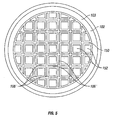
- the screen frame 103 may include a peripheral screen frame 102 and an internal support frame 150.
- the internal support frame 150 is formed with and is contiguous with the peripheral screen frame 102 to create a plurality of openings 152 within the screen frame 103.
- the screen cloth 104 (shown in FIGS. 1 , 3A - D , 4 ) may be affixed to the internal support frame 150.
- the internal support frame 150 includes a rigid support section 106' and strain relief zone 108'.
- each opening 152 defined by the internal support frame 150 has a strain relief zone 108' around its periphery. Such a configuration is desirable when it is anticipated that the screen cloth 104 will be subjected to heavy loads.
- an internal support frame 150 is possible with equally applicable rigid support section 106' and strain relief zone 108' configurations.
- an internal support frame 150 creating openings 152 having a pie shape may be desirable, wherein the strain relief zones 108' are present around each opening 152.
- the described screen frame 103' may be rectangular in shape, as shown in FIG. 6 , having a peripheral frame 102' with or without an internal support frame 150.
- the screen frame 103' would include a rigid support section 106 and a strain relief zone 108 around each opening 152 within the screen frame 103'.
Landscapes
- Chemical & Material Sciences (AREA)
- Chemical Kinetics & Catalysis (AREA)
- Combined Means For Separation Of Solids (AREA)
- Separation Of Solids By Using Liquids Or Pneumatic Power (AREA)
- Laminated Bodies (AREA)
- Mirrors, Picture Frames, Photograph Stands, And Related Fastening Devices (AREA)
- Two-Way Televisions, Distribution Of Moving Picture Or The Like (AREA)
- Endoscopes (AREA)
- Vessels, Lead-In Wires, Accessory Apparatuses For Cathode-Ray Tubes (AREA)
- Cold Cathode And The Manufacture (AREA)
- Liquid Crystal (AREA)
Claims (21)
- Siebanordnung (100) für ein Schütteltrennvorrichtung, die Folgendes umfasst:einen Umfangsrahmen (102) um eine Öffnung (105) herum, wobei der Rahmen (102) eine obere Befestigungsfläche (110) aufweist;zumindest ein Siebgewebe (104), das an der oberen Befestigungsfläche (110) oberhalb der Öffnung (105) befestigt ist, wobei das Siebgewebe (104) eine obere Siebfläche (130) und eine untere Siebfläche aufweist;wobei der Umfangsrahmen (102) Folgendes umfasst:einen starren Trägerabschnitt (106), an dem das Siebgewebe (104) befestigt wird; undeinen gepolsterten Entlastungsbereich (108), der zwischen dem starren Trägerabschnitt (106) und der Öffnung (105) an die obere Befestigungsfläche (110) angrenzend so angeordnet ist, dass die untere Siebfläche auf dem Entlastungsbereich (108) aufliegt;dadurch gekennzeichnet, dass:der starre Trägerabschnitt (106) aus einem Polymermaterial besteht undein Verstärkungselement (134) in dem starren Trägerabschnitt (106) des Umfangsrahmens (102) eingeschlossen ist.
- Siebanordnung nach Anspruch 1, worin das Polymermaterial, das den starren Trägerabschnitt (106) des Umfangsrahmens (102) bildet, einen ersten Durometerwert aufweist; worin der Entlastungsbereich (108) aus einem zweiten Material mit einem zweiten Durometerwert besteht; und worin der zweite Durometerwert geringer ist als der erste Durometerwert.
- Siebanordnung nach Anspruch 2, worin das erste Material ein erstes Polymer ist und das zweite Material ein zweites Polymer ist.
- Siebanordnung nach Anspruch 1, worin der Umfangsrahmen (102) ferner Folgendes umfasst: einen Flansch (138), der sich radial nach außen erstreckt, wobei der Flansch (138) aus dem ersten Polymer besteht.
- Siebanordnung nach Anspruch 4, worin der Entlastungsbereich (108) durch Extrusion des zweiten Polymers ausgebildet wird; und worin der starre Trägerabschnitt (106) des Umfangsrahmens (102) eine Nut (146) aufweist, in der das Extrusionsprodukt so eingelegt wird, dass dieses eine Auflage für die untere Siebfläche bildet.
- Siebanordnung nach Anspruch 4, worin der Entlastungsbereich (108) und der starre Trägerabschnitt (106) gemeinsam geformt werden.
- Siebanordnung nach Anspruch 1, die ferner Folgendes umfasst:einen inneren Trägerrahmen (150), der an den Umfangsrahmen (102) angrenzt unddie Öffnung (105) in eine Vielzahl von Öffnungen (152) unterteilt;worin der innere Trägerrahmen (150) Folgendes umfasst:einen inneren starren Trägerabschnitt (106') mit einer inneren oberen Befestigungsfläche (110), an der das Siebgewebe befestigt ist; undeinen inneren gepolsterten Entlastungsbereich (108'), der zwischen dem inneren starren Trägerabschnitt (106') und jeder Öffnung (152), die in Bezug auf die obere Befestigungsfläche benachbart vorliegt, angeordnet ist, sodass die untere Siebfläche auf dem Entlastungsbereich (108') aufliegt.
- Siebanordnung nach Anspruch 7, worin der innere starre Trägerabschnitt (106') aus einem ersten Polymer mit einem ersten Durometerwert besteht; worin der innere Entlastungsbereich (108') aus einem zweiten Material mit einem zweiten Durometerwert besteht; und worin der erste Durometerwert größer ist als der zweite Durometerwert.
- Rahmen (103) für eine Siebanordnung (100) zur Verwendung in einer Schütteltrennvorrichtung, worin die Siebanordnung (100) zumindest ein Siebgewebe (104) mit einer unteren Siebfläche umfasst, wobei der Rahmen (103) Folgendes umfasst:einen starren Trägerabschnitt (106) mit einer Öffnung (105), die durch diesen hindurch verläuft, worin das Siebgewebe (104) an dem starren Trägerabschnitt (106) oberhalb der Öffnung (105) angebracht ist; undeinen gepolsterten Entlastungsbereich (108), der zwischen dem starren Trägerabschnitt (106) und der Öffnung (105) an das Siebgewebe (104) so angrenzend angeordnet ist, dass die untere Fläche des Siebgewebes, die in Bezug auf die Öffnung (105) angrenzend angeordnet ist, auf dem Entlastungsbereich (108) aufliegt;dadurch gekennzeichnet, dass:der starre Trägerabschnitt (106) aus einem Polymermaterial ausgebildet ist undein Verstärkungselement (134) in dem starren Trägerabschnitt (106) angeordnet ist.
- Rahmen nach Anspruch 9, worin der starre Trägerabschnitt (106) ferner Folgendes umfasst: einen Flansch (138), der sich von einem Rahmenumfang nach außen erstreckt; und worin der Entlastungsbereich (108) den Flansch (138) einschließt.
- Rahmen nach Anspruch 9, worin der starre Trägerabschnitt (106) aus einem ersten Polymermaterial mit einem ersten Durometerwert besteht und der Entlastungsbereich (108) aus einem zweiten Polymermaterial mit einem zweiten Durometerwert besteht; und worin der erste Durometerwert größer ist als der zweite Durometerwert.
- Rahmen nach Anspruch 11, worin der starre Trägerabschnitt (106) eine obere Befestigungsfläche (110) umfasst; und worin das Siebgewebe (104) an der oberen Befestigungsfläche (110) des starren Trägerabschnitts (106) befestigt ist.
- Rahmen nach Anspruch 11, worin der Entlastungsbereich (108) durch Extrusion des zweiten Polymers ausgebildet wird; und worin der starre Trägerabschnitt (106) des Umfangsrahmens (102) eine Nut (146) aufweist, in der das Extrusionsprodukt so eingelegt wird, dass dieses eine Auflage für die untere Siebfläche bildet.
- Rahmen nach Anspruch 11, worin der starre Trägerabschnitt (106) aus einem ersten Polymer besteht und der Entlastungsbereich (108) aus einem zweiten Polymer besteht; und worin das starre Trägerelement (106) und der Entlastungsbereich (108) gemeinsam geformt werden.
- Rahmen nach Anspruch 11, worin das erste Polymer ein thermoplastisches Polymer ist; und worin das zweite Polymer ein Elastomermaterial ist.
- Rahmen nach Anspruch 11, worin das erste Polymer Polypropylen ist; und worin das zweite Polymer ein thermoplastisches Elastomer ist.
- Siebanordnung (100) für eine Schütteltrennvorrichtung, die Folgendes umfasst:einen Umfangsrahmen (102) um eine Öffnung (105);einen inneren Trägerrahmen (150), der an den Umfangsrahmen (102) angrenzt unddie Öffnung (105) in eine Vielzahl an Öffnungen (152) unterteilt;worin der Umfangsrahmen (102) und der innere Trägerrahmen (150) jeweils Folgendes umfassen:einen starren Trägerabschnitt (106, 106') mit einer oberen Befestigungsfläche (110), der aus einem ersten Material mit einem ersten Durometerwert gebildet ist;ein Verstärkungselement (134), das in dem starren Trägerabschnitt (106, 106') des Umfangsrahmens (102) eingeschlossen ist; undeinen gepolsterten Entlastungsbereich (108, 108') aus einem zweiten Material mit einem zweiten Durometerwert;worin der Entlastungsbereich (108, 108') benachbart in Bezug auf den oberen Befestigungsbereich (110) des starren Trägerabschnitts (106, 106') angeordnet ist; undworin der erste Durometerwert größer ist als der zweite Durometerwert;ein Siebgewebe (104), das über alle Öffnungen (105, 150) gespannt ist und an der oberen Befestigungsfläche (110) befestigt ist; undworin der Entlastungsbereich (108, 108') gegen das Siebgewebe (104) um jede der Öffnungen (105, 150) vorliegt.
- Siebanordnung nach Anspruch 17, die ferner Folgendes umfasst: einen Flansch (138), der sich von dem Umfangsrahmen (102) radial nach außen erstreckt, worin der Flansch (138) aus dem ersten Material besteht.
- Siebanordnung nach Anspruch 18, worin der starre Trägerabschnitt (106, 106') und der Entlastungsbereich (108, 108') gemeinsam geformt werden.
- Siebanordnung nach Anspruch 19, worin der Entlastungsbereich (108, 108') den Flansch (138) einschließt.
- Siebanordnung nach Anspruch 19, worin der Entlastungsbereich (108, 108') aus einem extrudierten Entlastungskissen besteht, das eine Rippe (144), die sich von einer unteren Fläche (120) weg erstreckt, umfasst; und worin der starre Trägerabschnitt (106, 106') eine entsprechende Nut (146) umfasst, um die Rippe (144) aufzunehmen und das Entlastungskissen an der gewünschten Position zu halten.
Applications Claiming Priority (2)
| Application Number | Priority Date | Filing Date | Title |
|---|---|---|---|
| US11/128,787 US7249677B2 (en) | 2005-05-13 | 2005-05-13 | Dual hardness composite screen frame |
| PCT/US2006/018800 WO2006124815A1 (en) | 2005-05-13 | 2006-05-15 | Dual hardness composite screen frame |
Publications (3)
| Publication Number | Publication Date |
|---|---|
| EP1879681A1 EP1879681A1 (de) | 2008-01-23 |
| EP1879681A4 EP1879681A4 (de) | 2009-05-20 |
| EP1879681B1 true EP1879681B1 (de) | 2011-03-30 |
Family
ID=37418099
Family Applications (1)
| Application Number | Title | Priority Date | Filing Date |
|---|---|---|---|
| EP06770389A Expired - Lifetime EP1879681B1 (de) | 2005-05-13 | 2006-05-15 | Verbundabschirmungsrahmen von doppelter härte |
Country Status (12)
| Country | Link |
|---|---|
| US (2) | US7249677B2 (de) |
| EP (1) | EP1879681B1 (de) |
| JP (1) | JP5074385B2 (de) |
| KR (1) | KR101312232B1 (de) |
| CN (1) | CN100594050C (de) |
| AT (1) | ATE503543T1 (de) |
| CA (1) | CA2605546C (de) |
| DE (1) | DE602006021002D1 (de) |
| EA (1) | EA011535B1 (de) |
| MX (1) | MX2007014149A (de) |
| NO (1) | NO339434B1 (de) |
| WO (1) | WO2006124815A1 (de) |
Families Citing this family (21)
| Publication number | Priority date | Publication date | Assignee | Title |
|---|---|---|---|---|
| US7249677B2 (en) * | 2005-05-13 | 2007-07-31 | M-I L.L.C. | Dual hardness composite screen frame |
| US7866482B2 (en) * | 2005-07-05 | 2011-01-11 | M-I Llc | Molded end cap for oilfield screens |
| US20080078705A1 (en) * | 2006-09-29 | 2008-04-03 | M-I Llc | Shaker wedge |
| US8393474B2 (en) * | 2006-09-29 | 2013-03-12 | United Wire Limited | Injection molded grid for saving screen frames |
| US7891497B2 (en) * | 2006-09-29 | 2011-02-22 | M-I L.L.C. | Peripheral sealing system for pre-tensioned screens |
| ZA201006277B (en) * | 2009-08-28 | 2012-01-25 | Allan Maskew (Pty) Ltd | A mine screen |
| DE102009029244A1 (de) * | 2009-09-07 | 2011-03-10 | Huber Se | Filtersegment für den Einsatz in einer Filtrationsvorrichtung sowie Kreissegment zur Aufnahme eines Filtersegments |
| US20150165481A1 (en) * | 2010-10-28 | 2015-06-18 | Grant Young | Shaker Seal |
| WO2012115634A1 (en) * | 2011-02-23 | 2012-08-30 | Michigan Adhesive Manufacturing, Inc. | Form-in-place gasket for shaker screen |
| AU2013266932B2 (en) | 2012-05-25 | 2018-07-19 | Derrick Corporation | Injection molded screening apparatuses and methods |
| US11161150B2 (en) | 2012-05-25 | 2021-11-02 | Derrick Corporation | Injection molded screening apparatuses and methods |
| US9409209B2 (en) | 2012-05-25 | 2016-08-09 | Derrick Corporation | Injection molded screening apparatuses and methods |
| US10576502B2 (en) | 2012-05-25 | 2020-03-03 | Derrick Corporation | Injection molded screening apparatuses and methods |
| US9393598B2 (en) | 2012-07-27 | 2016-07-19 | M-I L.L.C. | Composite screen frame with semi-flexible mechanical strain relief |
| AU2015217239B2 (en) * | 2014-02-11 | 2016-09-08 | Reald Inc. | Strain relieved mounting method and apparatus for screen material |
| US10711545B2 (en) * | 2015-05-03 | 2020-07-14 | Elgin Separation Solutions Industrials, Llc | Shale shaker with stair-stepped arrangements of screens and methods of using same, and methods of retrofitting shale shakers |
| US11505638B2 (en) | 2017-04-28 | 2022-11-22 | Derrick Corporation | Thermoplastic compositions, methods, apparatus, and uses |
| AU2018260541A1 (en) | 2017-04-28 | 2019-11-07 | Derrick Corporation | Thermoplastic compositions, methods, apparatus, and uses |
| WO2018226878A1 (en) | 2017-06-06 | 2018-12-13 | Derrick Corporation | Method and apparatuses for screening |
| US11213857B2 (en) | 2017-06-06 | 2022-01-04 | Derrick Corporation | Method and apparatus for screening |
| IT201800002719A1 (it) * | 2018-02-15 | 2019-08-15 | Vibrotech S R L | Supporto perfezionato per la rete di un vaglio |
Family Cites Families (71)
| Publication number | Priority date | Publication date | Assignee | Title |
|---|---|---|---|---|
| US532219A (en) * | 1895-01-08 | spiel | ||
| US2228180A (en) * | 1940-04-29 | 1941-01-07 | Hjalmar I Pauli | Game |
| US2474573A (en) * | 1947-04-21 | 1949-06-28 | Cohen Abe Henry | Game board of the lotto type |
| US3289837A (en) * | 1964-04-27 | 1966-12-06 | Wallace E Bixby | Screen panel |
| US3589729A (en) * | 1969-05-01 | 1971-06-29 | Jean Girard | Board game apparatus with spinners |
| DE2443370C2 (de) * | 1974-09-11 | 1982-09-16 | Klöckner-Humboldt-Deutz AG, 5000 Köln | Schwingsieb mit Unwuchtantrieb |
| JPS596710B2 (ja) * | 1974-10-18 | 1984-02-14 | 日清製粉 (株) | 粉体篩枠 |
| AT344629B (de) * | 1976-05-21 | 1978-08-10 | Steinhaus Gmbh | Siebfeld |
| ZA774472B (en) * | 1977-07-25 | 1979-06-27 | Herrmann Screens Mfg Co Ltd | Improvements in or relating to screening apparatus |
| GB2087265A (en) | 1980-11-06 | 1982-05-26 | Carrington Viyella Ltd | Sieves |
| US4341627A (en) * | 1981-05-06 | 1982-07-27 | The Brandt Company | Screen separator |
| US4413822A (en) * | 1981-07-31 | 1983-11-08 | American Sports Equipment | Elastic core composite structure and method of making same |
| US4375408A (en) * | 1981-08-05 | 1983-03-01 | Uop Inc. | Elastomeric framing member for screen deck panel |
| JPS6133679U (ja) | 1984-07-31 | 1986-02-28 | 株式会社 安藤スクリ−ン製作所 | 振動篩機における篩網の緊張装置 |
| JPS61212369A (ja) * | 1985-03-18 | 1986-09-20 | 関西金網株式会社 | 振動篩機用篩網板およびその製造方法 |
| US4665907A (en) * | 1985-12-11 | 1987-05-19 | Leverette Charles R | Apparatus for inhibiting digit sucking |
| JPH0141510Y2 (de) * | 1986-06-17 | 1989-12-07 | ||
| JPH0315185Y2 (de) * | 1986-09-27 | 1991-04-03 | ||
| US4836553A (en) * | 1988-04-18 | 1989-06-06 | Caribbean Stud Enterprises, Inc. | Poker game |
| US4832834A (en) * | 1988-07-11 | 1989-05-23 | Baird Jr Howard R | Elastomer sieve screen |
| DE3928872A1 (de) * | 1989-08-31 | 1991-03-21 | Rheinische Werkzeug & Maschf | Analysensiebgeraet |
| US5042818A (en) * | 1989-12-01 | 1991-08-27 | Gary Weingardt | Multi-deck poker game |
| US5429856A (en) * | 1990-03-30 | 1995-07-04 | Minnesota Mining And Manufacturing Company | Composite materials and process |
| US5167413A (en) * | 1990-10-30 | 1992-12-01 | D.D. Stud, Inc. | Method of playing a poker-type game and apparatus therefor |
| US5100137A (en) * | 1990-10-30 | 1992-03-31 | D.D. Stud, Inc. | Electronic poker-type game |
| US5112058A (en) * | 1990-11-08 | 1992-05-12 | Lowell Sandeen | Game card |
| US5165693A (en) * | 1991-03-08 | 1992-11-24 | Handlon Sr Charles J | Method of playing a bowling card game |
| US5118109A (en) * | 1991-04-30 | 1992-06-02 | Champions Management Group, Inc. | Instant poker game card |
| US5154429A (en) * | 1992-02-24 | 1992-10-13 | Four Queens, Inc. | Method of playing multiple action blackjack |
| US5280915A (en) * | 1992-12-21 | 1994-01-25 | Groussman Raymond K | Method of playing double action blackjack |
| US5265882A (en) * | 1993-02-11 | 1993-11-30 | Malek Mehrdad M | Method and apparatus of playing a new casino game |
| US5328189A (en) * | 1993-02-11 | 1994-07-12 | Malek Mehrdad M | Method and apparatus of playing a new casino game |
| US5544892A (en) * | 1993-02-25 | 1996-08-13 | Shuffle Master, Inc. | Multi-tiered wagering method and game |
| US5288081A (en) * | 1993-02-25 | 1994-02-22 | Shuffle Master, Inc. | Method of playing a wagering game |
| US5356140A (en) * | 1993-04-14 | 1994-10-18 | Dabrowski Stanley P | Double poker |
| US6607080B2 (en) * | 1993-04-30 | 2003-08-19 | Varco I/P, Inc. | Screen assembly for vibratory separators |
| US6581781B1 (en) * | 1993-04-30 | 2003-06-24 | Tuboscope I/P, Inc. | Vibrator separator screens |
| US5320356A (en) * | 1993-08-23 | 1994-06-14 | Fast Action Games Tech., Inc. | Method of playing fast action blackjack |
| US5377993A (en) * | 1994-03-04 | 1995-01-03 | Josephs; Ronald H. | Wagering game |
| JPH07275432A (ja) * | 1994-04-05 | 1995-10-24 | Eagle:Kk | スロットマシン |
| AUPM759994A0 (en) * | 1994-08-22 | 1994-09-15 | Aristocrat Leisure Industries Pty Ltd | Multi-line gaming machine |
| US5573249A (en) * | 1994-08-26 | 1996-11-12 | Johnson; Phillip | Card game |
| US5542669A (en) * | 1994-09-23 | 1996-08-06 | Universal Distributing Of Nevada, Inc. | Method and apparatus for randomly increasing the payback in a video gaming apparatus |
| US5486005A (en) * | 1995-01-03 | 1996-01-23 | Judith Neal, Executrix | Method and apparatus for playing a poker-like game |
| US5452899A (en) * | 1995-01-04 | 1995-09-26 | Skratulia; John | Method of playing a wagering game |
| US5496038A (en) * | 1995-02-24 | 1996-03-05 | Kangsanaraks; Adisorn | Card game |
| US5725428A (en) * | 1995-03-09 | 1998-03-10 | Atronic Casino Technology Distribution Gmbh | Video slot machine |
| US5882259A (en) * | 1995-03-30 | 1999-03-16 | Holmes, Jr.; Verne F. | Method of playing an electronic video card game |
| US5823873A (en) * | 1995-06-28 | 1998-10-20 | Moody Ernest W | Method of playing electronic video poker games |
| US5577731A (en) * | 1995-07-24 | 1996-11-26 | Progressive Games, Inc. | Method of progressive jackpot twenty-one wherein the predetermined winning arrangement of cards include two aces, three aces and four aces |
| US5819952A (en) * | 1995-08-29 | 1998-10-13 | United Wire Limited | Sifting screen |
| US5879233A (en) * | 1996-03-29 | 1999-03-09 | Stupero; John R. | Duplicate card game |
| US5664781A (en) * | 1996-09-30 | 1997-09-09 | New Vision Gaming And Development, Inc. | Method and apparatus for playing a poker-type card game |
| US5639092A (en) * | 1996-08-07 | 1997-06-17 | Macaisa; Renato L. | Method of playing a casino table game having multiple casino games |
| US5813911A (en) * | 1996-08-21 | 1998-09-29 | Bally Gaming, Inc. | Pattern keno game |
| US5816915A (en) * | 1996-08-27 | 1998-10-06 | Kadlic; Thomas P. | Pick one poker method of play |
| US5868618A (en) * | 1996-09-30 | 1999-02-09 | Neil J. Netley | Poker game method |
| GB2337019B (en) * | 1997-03-01 | 2001-06-13 | United Wire Ltd | Improved filtering screen and support frame therefor |
| US5743530A (en) * | 1997-03-24 | 1998-04-28 | Sklad Enterprises, Inc. | Method and apparatus for a card game |
| DE19825617A1 (de) * | 1998-06-08 | 1999-12-09 | Filip Gmbh Muellereibuersten | Vorrichtung zur Siebrahmen- und Bodenreinigung eines Siebkastens |
| US5927511A (en) * | 1998-06-29 | 1999-07-27 | Southwestern Wire Cloth, Inc. | Flat screen panel for crowned deck vibrating shaker |
| US5950841A (en) * | 1998-07-22 | 1999-09-14 | Emerson Electric Co. | Screen assembly for a vibratory separator |
| US20030042179A1 (en) * | 1998-10-30 | 2003-03-06 | Adams Thomas C. | Vibratory separator screens |
| JP2002001220A (ja) | 2000-06-26 | 2002-01-08 | Ando Screen Seisakusho:Kk | 振動篩用網 |
| US6726285B2 (en) * | 2000-07-03 | 2004-04-27 | Herman Miller, Inc. | Cellular chair construction |
| DE10106499A1 (de) * | 2001-02-13 | 2002-08-29 | Isenmann Siebe Gmbh | Sieb mit spalt- oder schlitzförmigen Sieböffnungen |
| US20050224398A1 (en) * | 2001-10-19 | 2005-10-13 | Largent David W | Vibratory separators and sealing screens |
| US6736271B1 (en) * | 2001-12-17 | 2004-05-18 | Peter C. Hall | Screen apparatus and method |
| US6893594B2 (en) * | 2003-06-20 | 2005-05-17 | Kuei Yung Wang Chen | Extruded window and door composite frames |
| US7150358B2 (en) * | 2004-04-30 | 2006-12-19 | M-I L.L.C. | Shaker screen clamping and sealing assembly |
| US7249677B2 (en) * | 2005-05-13 | 2007-07-31 | M-I L.L.C. | Dual hardness composite screen frame |
-
2005
- 2005-05-13 US US11/128,787 patent/US7249677B2/en not_active Expired - Lifetime
-
2006
- 2006-05-15 WO PCT/US2006/018800 patent/WO2006124815A1/en not_active Ceased
- 2006-05-15 JP JP2008511464A patent/JP5074385B2/ja not_active Expired - Fee Related
- 2006-05-15 MX MX2007014149A patent/MX2007014149A/es active IP Right Grant
- 2006-05-15 CN CN200680016570A patent/CN100594050C/zh not_active Expired - Lifetime
- 2006-05-15 EP EP06770389A patent/EP1879681B1/de not_active Expired - Lifetime
- 2006-05-15 EA EA200702494A patent/EA011535B1/ru not_active IP Right Cessation
- 2006-05-15 DE DE602006021002T patent/DE602006021002D1/de not_active Expired - Lifetime
- 2006-05-15 CA CA2605546A patent/CA2605546C/en not_active Expired - Lifetime
- 2006-05-15 KR KR1020077028990A patent/KR101312232B1/ko not_active Expired - Fee Related
- 2006-05-15 AT AT06770389T patent/ATE503543T1/de not_active IP Right Cessation
-
2007
- 2007-07-09 US US11/774,829 patent/US7389882B2/en not_active Expired - Lifetime
- 2007-11-06 NO NO20075630A patent/NO339434B1/no unknown
Also Published As
| Publication number | Publication date |
|---|---|
| US20060254961A1 (en) | 2006-11-16 |
| MX2007014149A (es) | 2008-02-07 |
| CN101175544A (zh) | 2008-05-07 |
| CN100594050C (zh) | 2010-03-17 |
| US7249677B2 (en) | 2007-07-31 |
| JP2008540103A (ja) | 2008-11-20 |
| EA200702494A1 (ru) | 2008-04-28 |
| EP1879681A4 (de) | 2009-05-20 |
| ATE503543T1 (de) | 2011-04-15 |
| KR20080015105A (ko) | 2008-02-18 |
| WO2006124815A1 (en) | 2006-11-23 |
| NO339434B1 (no) | 2016-12-12 |
| EP1879681A1 (de) | 2008-01-23 |
| US20070267332A1 (en) | 2007-11-22 |
| CA2605546A1 (en) | 2006-11-23 |
| CA2605546C (en) | 2013-12-31 |
| JP5074385B2 (ja) | 2012-11-14 |
| DE602006021002D1 (de) | 2011-05-12 |
| US7389882B2 (en) | 2008-06-24 |
| EA011535B1 (ru) | 2009-04-28 |
| KR101312232B1 (ko) | 2013-09-27 |
| NO20075630L (no) | 2007-12-11 |
Similar Documents
| Publication | Publication Date | Title |
|---|---|---|
| US7389882B2 (en) | Multi-hardness composite screen frame | |
| US8113358B2 (en) | Pre-tensioned sifter screen | |
| US9908150B2 (en) | Polyurethane screen | |
| US9296028B2 (en) | Flanged perforated metal plate for separation of pellets and particles | |
| KR101336008B1 (ko) | 진동 선별기의 원료선별장치 | |
| GB2478865A (en) | Filter screen with tension element | |
| WO2007115089A2 (en) | Composite screen | |
| AU2020227061B2 (en) | Polyurethane screen | |
| US9393598B2 (en) | Composite screen frame with semi-flexible mechanical strain relief | |
| US10799818B2 (en) | Gasket for screen frame | |
| KR102639544B1 (ko) | 플라스틱재를 이용한 집진기용 필터 카트리지 기구 | |
| CN106733633B (zh) | 等压筛片夹紧装置 | |
| WO2026077933A1 (en) | Seal for a sieve frame | |
| US9694392B2 (en) | Screen panel frame with plate |
Legal Events
| Date | Code | Title | Description |
|---|---|---|---|
| PUAI | Public reference made under article 153(3) epc to a published international application that has entered the european phase |
Free format text: ORIGINAL CODE: 0009012 |
|
| 17P | Request for examination filed |
Effective date: 20071107 |
|
| AK | Designated contracting states |
Kind code of ref document: A1 Designated state(s): AT BE BG CH CY CZ DE DK EE ES FI FR GB GR HU IE IS IT LI LT LU LV MC NL PL PT RO SE SI SK TR |
|
| DAX | Request for extension of the european patent (deleted) | ||
| A4 | Supplementary search report drawn up and despatched |
Effective date: 20090420 |
|
| 17Q | First examination report despatched |
Effective date: 20090805 |
|
| GRAP | Despatch of communication of intention to grant a patent |
Free format text: ORIGINAL CODE: EPIDOSNIGR1 |
|
| GRAS | Grant fee paid |
Free format text: ORIGINAL CODE: EPIDOSNIGR3 |
|
| GRAA | (expected) grant |
Free format text: ORIGINAL CODE: 0009210 |
|
| AK | Designated contracting states |
Kind code of ref document: B1 Designated state(s): AT BE BG CH CY CZ DE DK EE ES FI FR GB GR HU IE IS IT LI LT LU LV MC NL PL PT RO SE SI SK TR |
|
| REG | Reference to a national code |
Ref country code: GB Ref legal event code: FG4D |
|
| REG | Reference to a national code |
Ref country code: CH Ref legal event code: EP |
|
| REG | Reference to a national code |
Ref country code: IE Ref legal event code: FG4D |
|
| REF | Corresponds to: |
Ref document number: 602006021002 Country of ref document: DE Date of ref document: 20110512 Kind code of ref document: P |
|
| REG | Reference to a national code |
Ref country code: DE Ref legal event code: R096 Ref document number: 602006021002 Country of ref document: DE Effective date: 20110512 |
|
| REG | Reference to a national code |
Ref country code: NL Ref legal event code: VDEP Effective date: 20110330 |
|
| PG25 | Lapsed in a contracting state [announced via postgrant information from national office to epo] |
Ref country code: LT Free format text: LAPSE BECAUSE OF FAILURE TO SUBMIT A TRANSLATION OF THE DESCRIPTION OR TO PAY THE FEE WITHIN THE PRESCRIBED TIME-LIMIT Effective date: 20110330 Ref country code: SE Free format text: LAPSE BECAUSE OF FAILURE TO SUBMIT A TRANSLATION OF THE DESCRIPTION OR TO PAY THE FEE WITHIN THE PRESCRIBED TIME-LIMIT Effective date: 20110330 Ref country code: GR Free format text: LAPSE BECAUSE OF FAILURE TO SUBMIT A TRANSLATION OF THE DESCRIPTION OR TO PAY THE FEE WITHIN THE PRESCRIBED TIME-LIMIT Effective date: 20110701 Ref country code: LV Free format text: LAPSE BECAUSE OF FAILURE TO SUBMIT A TRANSLATION OF THE DESCRIPTION OR TO PAY THE FEE WITHIN THE PRESCRIBED TIME-LIMIT Effective date: 20110330 |
|
| LTIE | Lt: invalidation of european patent or patent extension |
Effective date: 20110330 |
|
| PG25 | Lapsed in a contracting state [announced via postgrant information from national office to epo] |
Ref country code: FI Free format text: LAPSE BECAUSE OF FAILURE TO SUBMIT A TRANSLATION OF THE DESCRIPTION OR TO PAY THE FEE WITHIN THE PRESCRIBED TIME-LIMIT Effective date: 20110330 Ref country code: AT Free format text: LAPSE BECAUSE OF FAILURE TO SUBMIT A TRANSLATION OF THE DESCRIPTION OR TO PAY THE FEE WITHIN THE PRESCRIBED TIME-LIMIT Effective date: 20110330 Ref country code: CY Free format text: LAPSE BECAUSE OF FAILURE TO SUBMIT A TRANSLATION OF THE DESCRIPTION OR TO PAY THE FEE WITHIN THE PRESCRIBED TIME-LIMIT Effective date: 20110330 Ref country code: SI Free format text: LAPSE BECAUSE OF FAILURE TO SUBMIT A TRANSLATION OF THE DESCRIPTION OR TO PAY THE FEE WITHIN THE PRESCRIBED TIME-LIMIT Effective date: 20110330 |
|
| PG25 | Lapsed in a contracting state [announced via postgrant information from national office to epo] |
Ref country code: BE Free format text: LAPSE BECAUSE OF FAILURE TO SUBMIT A TRANSLATION OF THE DESCRIPTION OR TO PAY THE FEE WITHIN THE PRESCRIBED TIME-LIMIT Effective date: 20110330 |
|
| PG25 | Lapsed in a contracting state [announced via postgrant information from national office to epo] |
Ref country code: EE Free format text: LAPSE BECAUSE OF FAILURE TO SUBMIT A TRANSLATION OF THE DESCRIPTION OR TO PAY THE FEE WITHIN THE PRESCRIBED TIME-LIMIT Effective date: 20110330 Ref country code: PT Free format text: LAPSE BECAUSE OF FAILURE TO SUBMIT A TRANSLATION OF THE DESCRIPTION OR TO PAY THE FEE WITHIN THE PRESCRIBED TIME-LIMIT Effective date: 20110801 |
|
| PG25 | Lapsed in a contracting state [announced via postgrant information from national office to epo] |
Ref country code: ES Free format text: LAPSE BECAUSE OF FAILURE TO SUBMIT A TRANSLATION OF THE DESCRIPTION OR TO PAY THE FEE WITHIN THE PRESCRIBED TIME-LIMIT Effective date: 20110711 Ref country code: IS Free format text: LAPSE BECAUSE OF FAILURE TO SUBMIT A TRANSLATION OF THE DESCRIPTION OR TO PAY THE FEE WITHIN THE PRESCRIBED TIME-LIMIT Effective date: 20110730 Ref country code: RO Free format text: LAPSE BECAUSE OF FAILURE TO SUBMIT A TRANSLATION OF THE DESCRIPTION OR TO PAY THE FEE WITHIN THE PRESCRIBED TIME-LIMIT Effective date: 20110330 Ref country code: CZ Free format text: LAPSE BECAUSE OF FAILURE TO SUBMIT A TRANSLATION OF THE DESCRIPTION OR TO PAY THE FEE WITHIN THE PRESCRIBED TIME-LIMIT Effective date: 20110330 Ref country code: SK Free format text: LAPSE BECAUSE OF FAILURE TO SUBMIT A TRANSLATION OF THE DESCRIPTION OR TO PAY THE FEE WITHIN THE PRESCRIBED TIME-LIMIT Effective date: 20110330 |
|
| PG25 | Lapsed in a contracting state [announced via postgrant information from national office to epo] |
Ref country code: MC Free format text: LAPSE BECAUSE OF NON-PAYMENT OF DUE FEES Effective date: 20110531 Ref country code: NL Free format text: LAPSE BECAUSE OF FAILURE TO SUBMIT A TRANSLATION OF THE DESCRIPTION OR TO PAY THE FEE WITHIN THE PRESCRIBED TIME-LIMIT Effective date: 20110330 |
|
| REG | Reference to a national code |
Ref country code: CH Ref legal event code: PL |
|
| PG25 | Lapsed in a contracting state [announced via postgrant information from national office to epo] |
Ref country code: LI Free format text: LAPSE BECAUSE OF NON-PAYMENT OF DUE FEES Effective date: 20110531 Ref country code: CH Free format text: LAPSE BECAUSE OF NON-PAYMENT OF DUE FEES Effective date: 20110531 |
|
| PLBE | No opposition filed within time limit |
Free format text: ORIGINAL CODE: 0009261 |
|
| STAA | Information on the status of an ep patent application or granted ep patent |
Free format text: STATUS: NO OPPOSITION FILED WITHIN TIME LIMIT |
|
| PG25 | Lapsed in a contracting state [announced via postgrant information from national office to epo] |
Ref country code: PL Free format text: LAPSE BECAUSE OF FAILURE TO SUBMIT A TRANSLATION OF THE DESCRIPTION OR TO PAY THE FEE WITHIN THE PRESCRIBED TIME-LIMIT Effective date: 20110330 Ref country code: DK Free format text: LAPSE BECAUSE OF FAILURE TO SUBMIT A TRANSLATION OF THE DESCRIPTION OR TO PAY THE FEE WITHIN THE PRESCRIBED TIME-LIMIT Effective date: 20110330 |
|
| REG | Reference to a national code |
Ref country code: IE Ref legal event code: MM4A |
|
| 26N | No opposition filed |
Effective date: 20120102 |
|
| REG | Reference to a national code |
Ref country code: DE Ref legal event code: R097 Ref document number: 602006021002 Country of ref document: DE Effective date: 20120102 |
|
| PG25 | Lapsed in a contracting state [announced via postgrant information from national office to epo] |
Ref country code: IE Free format text: LAPSE BECAUSE OF NON-PAYMENT OF DUE FEES Effective date: 20110515 |
|
| PG25 | Lapsed in a contracting state [announced via postgrant information from national office to epo] |
Ref country code: IT Free format text: LAPSE BECAUSE OF FAILURE TO SUBMIT A TRANSLATION OF THE DESCRIPTION OR TO PAY THE FEE WITHIN THE PRESCRIBED TIME-LIMIT Effective date: 20110330 |
|
| PG25 | Lapsed in a contracting state [announced via postgrant information from national office to epo] |
Ref country code: LU Free format text: LAPSE BECAUSE OF NON-PAYMENT OF DUE FEES Effective date: 20110515 |
|
| PG25 | Lapsed in a contracting state [announced via postgrant information from national office to epo] |
Ref country code: BG Free format text: LAPSE BECAUSE OF FAILURE TO SUBMIT A TRANSLATION OF THE DESCRIPTION OR TO PAY THE FEE WITHIN THE PRESCRIBED TIME-LIMIT Effective date: 20110630 |
|
| PG25 | Lapsed in a contracting state [announced via postgrant information from national office to epo] |
Ref country code: TR Free format text: LAPSE BECAUSE OF FAILURE TO SUBMIT A TRANSLATION OF THE DESCRIPTION OR TO PAY THE FEE WITHIN THE PRESCRIBED TIME-LIMIT Effective date: 20110330 |
|
| PG25 | Lapsed in a contracting state [announced via postgrant information from national office to epo] |
Ref country code: HU Free format text: LAPSE BECAUSE OF FAILURE TO SUBMIT A TRANSLATION OF THE DESCRIPTION OR TO PAY THE FEE WITHIN THE PRESCRIBED TIME-LIMIT Effective date: 20110330 |
|
| REG | Reference to a national code |
Ref country code: FR Ref legal event code: PLFP Year of fee payment: 11 |
|
| REG | Reference to a national code |
Ref country code: FR Ref legal event code: PLFP Year of fee payment: 12 |
|
| REG | Reference to a national code |
Ref country code: FR Ref legal event code: PLFP Year of fee payment: 13 |
|
| P01 | Opt-out of the competence of the unified patent court (upc) registered |
Effective date: 20231216 |
|
| PGFP | Annual fee paid to national office [announced via postgrant information from national office to epo] |
Ref country code: FR Payment date: 20250310 Year of fee payment: 20 |
|
| PGFP | Annual fee paid to national office [announced via postgrant information from national office to epo] |
Ref country code: GB Payment date: 20250327 Year of fee payment: 20 |
|
| PGFP | Annual fee paid to national office [announced via postgrant information from national office to epo] |
Ref country code: DE Payment date: 20250319 Year of fee payment: 20 |
|
| REG | Reference to a national code |
Ref country code: DE Ref legal event code: R071 Ref document number: 602006021002 Country of ref document: DE |
|
| REG | Reference to a national code |
Ref country code: GB Ref legal event code: PE20 Expiry date: 20260514 |
|
| PG25 | Lapsed in a contracting state [announced via postgrant information from national office to epo] |
Ref country code: GB Free format text: LAPSE BECAUSE OF EXPIRATION OF PROTECTION Effective date: 20260514 |