EP1880936A2 - Amortisseur - Google Patents
Amortisseur Download PDFInfo
- Publication number
- EP1880936A2 EP1880936A2 EP07013336A EP07013336A EP1880936A2 EP 1880936 A2 EP1880936 A2 EP 1880936A2 EP 07013336 A EP07013336 A EP 07013336A EP 07013336 A EP07013336 A EP 07013336A EP 1880936 A2 EP1880936 A2 EP 1880936A2
- Authority
- EP
- European Patent Office
- Prior art keywords
- damping
- rebound
- damper according
- cylinder
- compression
- Prior art date
- Legal status (The legal status is an assumption and is not a legal conclusion. Google has not performed a legal analysis and makes no representation as to the accuracy of the status listed.)
- Granted
Links
Images
Classifications
-
- B—PERFORMING OPERATIONS; TRANSPORTING
- B62—LAND VEHICLES FOR TRAVELLING OTHERWISE THAN ON RAILS
- B62K—CYCLES; CYCLE FRAMES; CYCLE STEERING DEVICES; RIDER-OPERATED TERMINAL CONTROLS SPECIALLY ADAPTED FOR CYCLES; CYCLE AXLE SUSPENSIONS; CYCLE SIDECARS, FORECARS, OR THE LIKE
- B62K25/00—Axle suspensions
- B62K25/04—Axle suspensions for mounting axles resiliently on cycle frame or fork
-
- F—MECHANICAL ENGINEERING; LIGHTING; HEATING; WEAPONS; BLASTING
- F16—ENGINEERING ELEMENTS AND UNITS; GENERAL MEASURES FOR PRODUCING AND MAINTAINING EFFECTIVE FUNCTIONING OF MACHINES OR INSTALLATIONS; THERMAL INSULATION IN GENERAL
- F16F—SPRINGS; SHOCK-ABSORBERS; MEANS FOR DAMPING VIBRATION
- F16F9/00—Springs, vibration-dampers, shock-absorbers, or similarly-constructed movement-dampers using a fluid or the equivalent as damping medium
- F16F9/32—Details
- F16F9/53—Means for adjusting damping characteristics by varying fluid viscosity, e.g. electromagnetically
-
- B—PERFORMING OPERATIONS; TRANSPORTING
- B62—LAND VEHICLES FOR TRAVELLING OTHERWISE THAN ON RAILS
- B62K—CYCLES; CYCLE FRAMES; CYCLE STEERING DEVICES; RIDER-OPERATED TERMINAL CONTROLS SPECIALLY ADAPTED FOR CYCLES; CYCLE AXLE SUSPENSIONS; CYCLE SIDECARS, FORECARS, OR THE LIKE
- B62K25/00—Axle suspensions
- B62K25/04—Axle suspensions for mounting axles resiliently on cycle frame or fork
- B62K2025/048—Axle suspensions for mounting axles resiliently on cycle frame or fork with suspension manual adjustment details
Definitions
- the invention relates to a damper, in particular for two-wheelers, which has a cylinder and a damping piston guided therein, wherein on both sides of the damping piston cylinder chambers are filled with liquid as a damping medium, for a compression spring compression damping and rebound damping is provided for a rebound damping and wherein at least one of the two attenuations is electrorheologically or magnetorheologically adjustable.
- both the compression damping and the rebound damping can be controlled electrorheologically or magnetorheologically or one of the two damping is electrorheological or magnetorheological and the other hydraulically adjustable.
- electrorheological damping the damper fluid is located between electrodes to which an electrical voltage can be applied, while the damper fluid is in a (electro-) magnetic field during magnetorheological damping.
- dampers their pressure or rebound is damped by a guided in a cylinder piston, the cylinder chambers are usually connected by connecting channels with check valves (Newtonian damping). The adjustment of the rebound and compression can be done separately by adjustable throttles.
- dampers in which the pressure stage is dynamic electro-rheological or magnetorheological and the rebound is statically damped hydraulically. An independent adjustment of the rebound and compression damping as well as a dynamic adjustment of the rebound to the respective driving situation is not possible with these dampers.
- the change can be static or quasi-static, so that it does not change during operation, or dynamic (controlled or regulated), so that it is constantly changed during operation , which preferably can be done with an electronics, which determines the driving situation due to sensors.
- dynamic regulation of compression and rebound damping and purely electrorheological controlled systems are known in which the compression and rebound are damped differently. This can be done for example via a differential piston. If the rebound damping is to be independent of or separate from the compression damping, a complex control is necessary which changes the electrorheological voltage in real time, referred to below as ER voltage, depending on whether the spring element is on or off.
- both the compression damping and the rebound damping can be regulated electrorheologically or magnetorheologically.
- one of the two attenuations may be electrorheological or magnetorheological and the other hydraulically adjustable. In any case, independent settings of compression damping and rebound damping are easily possible.
- the outlay is therefore also considerably lower, since no sensors and accordingly no processing of measuring signals are necessary.
- a slower, more easily designed high voltage generator can be used to drive the electrorheological damping.
- the inventive design of the damper driving with increased ER voltage is easily possible. It can be set with the ER voltage an arbitrarily high compression damping, without affecting the rebound damping. This is advantageous, for example, when the pedal is to be suppressed when the bicycle is being pedaled.
- One way to dampen the pressure level is to set an ER voltage firmly. Due to the electrorheological properties of the hydraulic fluid, the compression damping in this case is relatively high, depending on the applied voltage up to a certain threshold force. Above this force threshold, ie as soon as a certain damper speed sets, the force is significantly lower in ER damper. In practice, this has the effect of suppressing movements up to a certain threshold of force and, above this threshold of force, the compression damping is low enough to allow rapid compression.
- the ER voltage is fixed by the operator, he sets thereby the threshold of the spring element.
- the spring element responds to strong impacts, resulting in a fail-save function in the form that, for example, a mountain biker in an unexpected obstacle does not receive such a strong blow that he is in danger to overthrow.
- the rebound damping is less than the compression, so that the fork rebounds again. This is possible with the damper according to the invention, so that such a spring element also provides sufficient safety in case of misuse in the form that is driven with blocked damping over an obstacle or in rough terrain.
- An advantageous development of the invention provides that in an electrorheological damping, in particular an electrorheological compression damping, a measuring and adjusting device for measuring the current consumption of the electrorheological damping device and for adjusting the damping is provided depending on the current consumption. This can be done by detecting the driving situation on the current consumption of the electrorheological damping device.
- the movements in the damper in an electrorheological attenuation lead with increasing movement to a measurable increase in power consumption, so that without additional sensors, a spring element can be realized, which reduces the compression damping practically automatically over the measuring and adjusting device with strong bumps.
- the system can be moved in any operating mode.
- An expedient embodiment of the invention provides an electrorheological or magnetorheological regulation of the compression damping and a hydraulic regulation of the rebound damping.
- the rebound damping and the compression damping are separated by non-return valves. This is technically relatively easy to implement and is susceptible to interference.
- the energy consumption of the damper is reduced overall compared to pure electrorheological systems.
- Electro-rheological regulation of compression damping and hydraulic rebound damping control can be used to adjust the rebound damping via an adjustable throttle, which is usually done once to accommodate the driver's weight and needs.
- the pressure stage is attenuated via an ER valve, whereby the compression damping is set via the ER voltage.
- An embodiment of the damper according to the invention provides that, as part of an electrorheological compression damping, the cylinder has an annular gap between an inner and an outer cylinder wall.
- the inner and outer cylinder wall for controlling the flow properties of which are located in the annular gap space Hydraulic fluid energized.
- Hydraulic fluid energized.
- these are connected by an electrically insulating connecting piece and form electrodes for the electrorheological application of the hydraulic medium in the annular gap.
- the annular gap space with the pressure chamber cylinder space forming a compression space when pressurized is direct and with the rebound cylinder chamber forming a compression space when subjected to tensile stress via a pressure stage check valve which is flow-through from the annular gap space to the rebound chamber.
- Cylinder room opens, connected.
- a rebound check valve may be disposed between the two cylinder chambers, preferably integrated in the damping piston, which opens to flow from the rebound cylinder chamber into the pressure stage cylinder chamber.
- the rebound-check valve can be adjustable to influence the damping characteristic of the rebound damping, in particular by adjusting the load of a valve closing member. As a result, the flow of damping medium through the rebound check valve is adjustable.
- a surge tank can be connected with a guided therein separating piston with the inner cylinder wall. It is particularly advantageous if the expansion tank is designed as a cylindrical attachment on the inner cylinder wall and if the insulating connector for connecting and for axially fixing the inner cylinder wall is used.
- the separating piston has a receiving chamber as a collecting device for the gaseous fractions and the receiving chamber of the separating piston with the pressure stages Cylinder space is connected via at least one connecting channel. In this way, the gaseous components of the hydraulic fluid can be absorbed and held by the separating piston.
- an embodiment of the damper according to the invention provides that the upper end region of the inner tube serves as a surge tank.
- the inner cylinder wall may have a stepped reduction in cross section at its upper end region and the connecting piece may be placed on this step.
- the expansion tank has at its outer end a separated by the separating piston outer chamber, which is formed as a dense air chamber.
- the gas volume located in the air chamber above the separating piston simultaneously serves as an air spring and additional damping element.
- the surge tank or the air chamber has a closure lid, which has a preferably designed as Einschraubventil air valve.
- the damper according to the invention can be used in any hydraulic tension / pressure system. It is advantageous, however, if the damper is part of a suspension fork and / or a strut for rear assemblies, especially in two-wheeled vehicles, because two-wheelers require a particularly flexible damping system due to their application, to provide a high level of driving safety and adequate ride comfort.
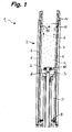
- a designated in Fig. 1 as a whole with 1 damper has a cylinder 2 and a guided therein damping piston 3, wherein on both sides of the damping piston 3 located cylinder chambers 4,5 and formed by an inner cylinder wall 6 and an outer cylinder wall 7 annular gap space 8 with liquid are filled as damping medium.
- One cylinder space forms a pressure stage cylinder space 4 and the other cylinder space forms a rebound cylinder space 5.
- a rebound check valve 10 is arranged, which opens to the flow from the rebound cylinder chamber 5 into the pressure stage cylinder chamber 4.
- the rebound check valve 10 is integrated in the damping piston 3.
- the hydraulic fluid marked by dots flows from the pressure stage cylinder chamber 4 via pressure transfer cylinder chamber 4 via overflow openings 15 (FIG. 1) into the annular gap space 8.
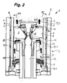
- the hydraulic fluid passes from the annular gap space 8 on the way to the rebound cylinder chamber 5, the pressure stage check valve 9, while the rebound check valve 10 remains closed.
- an electrorheologically variable damping is provided, wherein the inner cylinder wall 6 and the outer cylinder wall 7 with the annular gap space 8 are parts of the electrorheological system.
- the cylinder walls thereby form electrodes and the flow properties of the annular gap space 8 located hydraulic fluid can be changed by a voltage applied to the electrodes or optionally by an electromagnetic field in the annular gap space 8 (electrorheological).
- the damping piston 3 moves axially downwards in the direction of the pressure stage check valve 9 when the pressure stage check valve 9 is closed.
- the flow path for volume compensation of the hydraulic fluid between the cylinder chambers 4, 5 runs in the rebound damping of the rebound cylinder chamber 5 through the rebound check valve 10 in the pressure stage cylinder chamber. 4
- the hydraulic fluid passes through the electrorheological annular gap space 8 only in the compression damping, while in the rebound damping of the flow path of the hydraulic fluid passes directly through the damping piston 3 therethrough.
- a needle valve 11 is provided for adjusting the flow through the rebound check valve 10, which has a valve needle 12 and a valve seat 16 located in an inflow channel 13 of the rebound check valve 10.
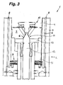
- the needle valve 11 is shown in an open position and in Fig. 3 in the closed position.
- the regulation of the flow of hydraulic fluid through the needle valve 11 disposed in series with the rebound check valve 10 affects the rebound damping independently of the compression damping. Conversely, for example, electrorheological compression damping has no effect on the rebound damping.
- the inner cylinder wall 6 and the outer one form Cylinder wall 7 for electrorheological admission of the hydraulic fluid in the annular gap 8 electrodes.
- the flow properties of the hydraulic fluid in the annular gap space 8 are thereby adjustable, whereby the damping properties of the compression damping can be changed.
- the inner cylinder wall 6 and the outer cylinder wall 7 are connected by an electrically insulating connecting piece 14.
- the connecting piece 14 can serve as a spacer for forming the annular gap space 8 between the inner cylinder wall 6 and the outer cylinder wall 7 and for fixing the inner cylinder wall 6.
- the damping piston 3 is shown in the closed state.
- the valve needle 12 closes the inflow channels 13 from liquid-tight. In this closed state, the rebound damping is blocked.
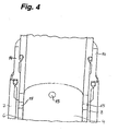
- an adjustment valve may be provided which has a valve plate for closing the flow openings, which is spring beaufschlagbar via a means of an adjusting needle axially adjustable counter-holder in the closing direction.
- the damping piston 3 at the outlet end of its flow openings in the support area on the flow openings outwardly conically tapered valve plate have inclined surfaces.
Landscapes
- Engineering & Computer Science (AREA)
- Mechanical Engineering (AREA)
- General Engineering & Computer Science (AREA)
- Physics & Mathematics (AREA)
- Electromagnetism (AREA)
- Fluid-Damping Devices (AREA)
- Buildings Adapted To Withstand Abnormal External Influences (AREA)
- Axle Suspensions And Sidecars For Cycles (AREA)
Applications Claiming Priority (1)
| Application Number | Priority Date | Filing Date | Title |
|---|---|---|---|
| DE102006033565A DE102006033565A1 (de) | 2006-07-20 | 2006-07-20 | Dämpfer |
Publications (3)
| Publication Number | Publication Date |
|---|---|
| EP1880936A2 true EP1880936A2 (fr) | 2008-01-23 |
| EP1880936A3 EP1880936A3 (fr) | 2009-01-14 |
| EP1880936B1 EP1880936B1 (fr) | 2010-09-15 |
Family
ID=38645999
Family Applications (1)
| Application Number | Title | Priority Date | Filing Date |
|---|---|---|---|
| EP07013336A Not-in-force EP1880936B1 (fr) | 2006-07-20 | 2007-07-07 | Amortisseur |
Country Status (3)
| Country | Link |
|---|---|
| EP (1) | EP1880936B1 (fr) |
| AT (1) | ATE481306T1 (fr) |
| DE (2) | DE102006033565A1 (fr) |
Cited By (2)
| Publication number | Priority date | Publication date | Assignee | Title |
|---|---|---|---|---|
| WO2010020428A1 (fr) * | 2008-08-22 | 2010-02-25 | Inventus Engineering Gmbh | Dispositif amortissant le mouvement |
| EP2468615A1 (fr) * | 2010-12-23 | 2012-06-27 | DT Swiss AG | Commande de châssis pour un vélo |
Families Citing this family (3)
| Publication number | Priority date | Publication date | Assignee | Title |
|---|---|---|---|---|
| DE102009060550B4 (de) | 2009-12-23 | 2024-06-20 | Dt Swiss Ag | Dämpfereinrichtung für ein Zweirad |
| DE102019215639A1 (de) * | 2019-10-11 | 2021-04-15 | Shimano Inc. | Hydraulische steuervorrichtung für ein bremssystem eines menschlich angetriebenen fahrzeugs und bremssystem mit einer solchen hydraulischen steuervorrichtung |
| CN112628276A (zh) * | 2020-12-22 | 2021-04-09 | 精海联科(宁波)智能设备有限公司 | 匀速开闭铰链机器人整机 |
Citations (1)
| Publication number | Priority date | Publication date | Assignee | Title |
|---|---|---|---|---|
| DE10320005B3 (de) | 2003-05-06 | 2004-10-21 | Zf Sachs Ag | Schwingungsdämpfer mit feldkraftabhängig regelbarer Dämpfkraft |
Family Cites Families (10)
| Publication number | Priority date | Publication date | Assignee | Title |
|---|---|---|---|---|
| JPS596448A (ja) * | 1982-07-02 | 1984-01-13 | Showa Mfg Co Ltd | 油圧緩衝器 |
| JPH0610984A (ja) * | 1992-06-26 | 1994-01-21 | Kayaba Ind Co Ltd | 緩衝器 |
| JPH0791479A (ja) * | 1993-09-27 | 1995-04-04 | Kayaba Ind Co Ltd | 緩衝器 |
| US6095486A (en) * | 1997-03-05 | 2000-08-01 | Lord Corporation | Two-way magnetorheological fluid valve assembly and devices utilizing same |
| DE19820570A1 (de) * | 1998-05-08 | 1999-11-11 | Schenck Ag Carl | Schwingungsdämpfer auf Basis elektrorheologischer und/oder magnetorheologischer Flüssigkeiten |
| US6279702B1 (en) * | 2001-01-05 | 2001-08-28 | Mando Corporation | Shock absorber using a hydraulic fluid and a magnetorheological fluid |
| US6419058B1 (en) * | 2001-03-30 | 2002-07-16 | Delphi Technologies, Inc. | Magnetorheological damper with piston bypass |
| DE10123381B4 (de) * | 2001-05-14 | 2006-04-06 | Horoschenkoff, Alexander, Dr. | Aktive Hinterradgabel für Zweiräder |
| DE10240568A1 (de) * | 2002-08-29 | 2004-03-11 | Fludicon Gmbh | Stoßdämpfungssystem für Zweiräder |
| DE10352176A1 (de) * | 2003-11-05 | 2005-06-02 | Fludicon Gmbh | Schwingungsdämpfer auf Basis elektrorheologischer und/oder magnetorheologischer Flüssigkeiten |
-
2006
- 2006-07-20 DE DE102006033565A patent/DE102006033565A1/de not_active Withdrawn
-
2007
- 2007-07-07 EP EP07013336A patent/EP1880936B1/fr not_active Not-in-force
- 2007-07-07 AT AT07013336T patent/ATE481306T1/de active
- 2007-07-07 DE DE502007005022T patent/DE502007005022D1/de active Active
Patent Citations (1)
| Publication number | Priority date | Publication date | Assignee | Title |
|---|---|---|---|---|
| DE10320005B3 (de) | 2003-05-06 | 2004-10-21 | Zf Sachs Ag | Schwingungsdämpfer mit feldkraftabhängig regelbarer Dämpfkraft |
Cited By (4)
| Publication number | Priority date | Publication date | Assignee | Title |
|---|---|---|---|---|
| WO2010020428A1 (fr) * | 2008-08-22 | 2010-02-25 | Inventus Engineering Gmbh | Dispositif amortissant le mouvement |
| US8430416B2 (en) | 2008-08-22 | 2013-04-30 | Inventus Engineering Gmbh | Movement damping apparatus |
| US8757652B2 (en) | 2008-08-22 | 2014-06-24 | Inventus Engineering Gmbh | Valve and movement damping apparatus |
| EP2468615A1 (fr) * | 2010-12-23 | 2012-06-27 | DT Swiss AG | Commande de châssis pour un vélo |
Also Published As
| Publication number | Publication date |
|---|---|
| EP1880936B1 (fr) | 2010-09-15 |
| EP1880936A3 (fr) | 2009-01-14 |
| DE502007005022D1 (de) | 2010-10-28 |
| DE102006033565A1 (de) | 2008-01-24 |
| ATE481306T1 (de) | 2010-10-15 |
Similar Documents
| Publication | Publication Date | Title |
|---|---|---|
| EP0602121B1 (fr) | Dispositif a soupape pilotable pour amortisseurs de vibrations bitubes reglables | |
| EP3403910B1 (fr) | Dispositif de traction, en particulier pour une bicyclette | |
| DE112016002019B4 (de) | Schwingungsdämpferanordnung | |
| DE102011053127A1 (de) | Feder-Dämpfervorrichtung für ein Fahrrad | |
| DE102010051872B4 (de) | Schwingungsdämpferanordnung | |
| EP3412928B1 (fr) | Dispositif d'amortissment traction, en particulier pour une bicyclette | |
| DE102007043617A1 (de) | Vorderrad-Tragstruktur | |
| DE19963415B4 (de) | Hydraulischer Stoßdämpfer mit Dämpfungskraftregelung | |
| DE102012016946A1 (de) | Federgabel, insbesondere für Fahrräder | |
| EP2260217A1 (fr) | Element de connexion elastique a rigidite variable | |
| EP1880936B1 (fr) | Amortisseur | |
| DE102012006928A1 (de) | Fahrwerksanordnung eines Kraftfahrzeugs mit einer zwei Federvorrichtungen aufweisenden Querstabilisierungsvorrichtung | |
| WO2019048160A1 (fr) | Ensemble stabilisateur commutable d'un véhicule | |
| EP2187086B1 (fr) | Fourche à ressort | |
| DE102008027134A1 (de) | Vorrichtung zur Beeinflussung des Fahrverhaltens eines Kraftfahrzeugs | |
| DE102006016047B3 (de) | Federsystem für einen Fahrzeugsitz | |
| DE102010060251B4 (de) | Radaufhängung für ein Kraftfahrzeug | |
| EP2977640B1 (fr) | Amortisseur d'oscillations | |
| EP2278186B1 (fr) | Dispositif d'amortissement pour un deux roues | |
| DE102012016947B4 (de) | Federgabel, insbesondere für Fahrräder | |
| EP2479097B1 (fr) | Jambe de fourche à ressort télescopique doté d'une butée terminale hydraulique | |
| DE102019111488A1 (de) | Stabilisatoranordnung eines zweispurigen Fahrzeuges | |
| DE102010021076A1 (de) | Federgabel | |
| DE10251213B4 (de) | Stoßdämpfer | |
| DE3729187C2 (de) | Verstellbare Dämpfung |
Legal Events
| Date | Code | Title | Description |
|---|---|---|---|
| PUAI | Public reference made under article 153(3) epc to a published international application that has entered the european phase |
Free format text: ORIGINAL CODE: 0009012 |
|
| AK | Designated contracting states |
Kind code of ref document: A2 Designated state(s): AT BE BG CH CY CZ DE DK EE ES FI FR GB GR HU IE IS IT LI LT LU LV MC MT NL PL PT RO SE SI SK TR |
|
| AX | Request for extension of the european patent |
Extension state: AL BA HR MK YU |
|
| PUAL | Search report despatched |
Free format text: ORIGINAL CODE: 0009013 |
|
| AK | Designated contracting states |
Kind code of ref document: A3 Designated state(s): AT BE BG CH CY CZ DE DK EE ES FI FR GB GR HU IE IS IT LI LT LU LV MC MT NL PL PT RO SE SI SK TR |
|
| AX | Request for extension of the european patent |
Extension state: AL BA HR MK RS |
|
| 17P | Request for examination filed |
Effective date: 20090619 |
|
| AKX | Designation fees paid |
Designated state(s): AT BE BG CH CY CZ DE DK EE ES FI FR GB GR HU IE IS IT LI LT LU LV MC MT NL PL PT RO SE SI SK TR |
|
| GRAP | Despatch of communication of intention to grant a patent |
Free format text: ORIGINAL CODE: EPIDOSNIGR1 |
|
| GRAS | Grant fee paid |
Free format text: ORIGINAL CODE: EPIDOSNIGR3 |
|
| GRAA | (expected) grant |
Free format text: ORIGINAL CODE: 0009210 |
|
| AK | Designated contracting states |
Kind code of ref document: B1 Designated state(s): AT BE BG CH CY CZ DE DK EE ES FI FR GB GR HU IE IS IT LI LT LU LV MC MT NL PL PT RO SE SI SK TR |
|
| REG | Reference to a national code |
Ref country code: GB Ref legal event code: FG4D Free format text: NOT ENGLISH Ref country code: CH Ref legal event code: EP |
|
| REG | Reference to a national code |
Ref country code: IE Ref legal event code: FG4D Free format text: LANGUAGE OF EP DOCUMENT: GERMAN |
|
| REF | Corresponds to: |
Ref document number: 502007005022 Country of ref document: DE Date of ref document: 20101028 Kind code of ref document: P |
|
| REG | Reference to a national code |
Ref country code: CH Ref legal event code: NV Representative=s name: HANS RUDOLF GACHNANG PATENTANWALT |
|
| REG | Reference to a national code |
Ref country code: NL Ref legal event code: VDEP Effective date: 20100915 |
|
| PG25 | Lapsed in a contracting state [announced via postgrant information from national office to epo] |
Ref country code: FI Free format text: LAPSE BECAUSE OF FAILURE TO SUBMIT A TRANSLATION OF THE DESCRIPTION OR TO PAY THE FEE WITHIN THE PRESCRIBED TIME-LIMIT Effective date: 20100915 Ref country code: LT Free format text: LAPSE BECAUSE OF FAILURE TO SUBMIT A TRANSLATION OF THE DESCRIPTION OR TO PAY THE FEE WITHIN THE PRESCRIBED TIME-LIMIT Effective date: 20100915 |
|
| LTIE | Lt: invalidation of european patent or patent extension |
Effective date: 20100915 |
|
| PG25 | Lapsed in a contracting state [announced via postgrant information from national office to epo] |
Ref country code: PL Free format text: LAPSE BECAUSE OF FAILURE TO SUBMIT A TRANSLATION OF THE DESCRIPTION OR TO PAY THE FEE WITHIN THE PRESCRIBED TIME-LIMIT Effective date: 20100915 Ref country code: CY Free format text: LAPSE BECAUSE OF FAILURE TO SUBMIT A TRANSLATION OF THE DESCRIPTION OR TO PAY THE FEE WITHIN THE PRESCRIBED TIME-LIMIT Effective date: 20100915 Ref country code: SI Free format text: LAPSE BECAUSE OF FAILURE TO SUBMIT A TRANSLATION OF THE DESCRIPTION OR TO PAY THE FEE WITHIN THE PRESCRIBED TIME-LIMIT Effective date: 20100915 |
|
| PG25 | Lapsed in a contracting state [announced via postgrant information from national office to epo] |
Ref country code: LV Free format text: LAPSE BECAUSE OF FAILURE TO SUBMIT A TRANSLATION OF THE DESCRIPTION OR TO PAY THE FEE WITHIN THE PRESCRIBED TIME-LIMIT Effective date: 20100915 Ref country code: SE Free format text: LAPSE BECAUSE OF FAILURE TO SUBMIT A TRANSLATION OF THE DESCRIPTION OR TO PAY THE FEE WITHIN THE PRESCRIBED TIME-LIMIT Effective date: 20100915 Ref country code: GR Free format text: LAPSE BECAUSE OF FAILURE TO SUBMIT A TRANSLATION OF THE DESCRIPTION OR TO PAY THE FEE WITHIN THE PRESCRIBED TIME-LIMIT Effective date: 20101216 |
|
| REG | Reference to a national code |
Ref country code: IE Ref legal event code: FD4D |
|
| PG25 | Lapsed in a contracting state [announced via postgrant information from national office to epo] |
Ref country code: IE Free format text: LAPSE BECAUSE OF FAILURE TO SUBMIT A TRANSLATION OF THE DESCRIPTION OR TO PAY THE FEE WITHIN THE PRESCRIBED TIME-LIMIT Effective date: 20100915 |
|
| PG25 | Lapsed in a contracting state [announced via postgrant information from national office to epo] |
Ref country code: PT Free format text: LAPSE BECAUSE OF FAILURE TO SUBMIT A TRANSLATION OF THE DESCRIPTION OR TO PAY THE FEE WITHIN THE PRESCRIBED TIME-LIMIT Effective date: 20110117 Ref country code: RO Free format text: LAPSE BECAUSE OF FAILURE TO SUBMIT A TRANSLATION OF THE DESCRIPTION OR TO PAY THE FEE WITHIN THE PRESCRIBED TIME-LIMIT Effective date: 20100915 Ref country code: EE Free format text: LAPSE BECAUSE OF FAILURE TO SUBMIT A TRANSLATION OF THE DESCRIPTION OR TO PAY THE FEE WITHIN THE PRESCRIBED TIME-LIMIT Effective date: 20100915 Ref country code: SK Free format text: LAPSE BECAUSE OF FAILURE TO SUBMIT A TRANSLATION OF THE DESCRIPTION OR TO PAY THE FEE WITHIN THE PRESCRIBED TIME-LIMIT Effective date: 20100915 Ref country code: IS Free format text: LAPSE BECAUSE OF FAILURE TO SUBMIT A TRANSLATION OF THE DESCRIPTION OR TO PAY THE FEE WITHIN THE PRESCRIBED TIME-LIMIT Effective date: 20110115 Ref country code: NL Free format text: LAPSE BECAUSE OF FAILURE TO SUBMIT A TRANSLATION OF THE DESCRIPTION OR TO PAY THE FEE WITHIN THE PRESCRIBED TIME-LIMIT Effective date: 20100915 Ref country code: CZ Free format text: LAPSE BECAUSE OF FAILURE TO SUBMIT A TRANSLATION OF THE DESCRIPTION OR TO PAY THE FEE WITHIN THE PRESCRIBED TIME-LIMIT Effective date: 20100915 |
|
| PG25 | Lapsed in a contracting state [announced via postgrant information from national office to epo] |
Ref country code: ES Free format text: LAPSE BECAUSE OF FAILURE TO SUBMIT A TRANSLATION OF THE DESCRIPTION OR TO PAY THE FEE WITHIN THE PRESCRIBED TIME-LIMIT Effective date: 20101226 |
|
| PLBE | No opposition filed within time limit |
Free format text: ORIGINAL CODE: 0009261 |
|
| STAA | Information on the status of an ep patent application or granted ep patent |
Free format text: STATUS: NO OPPOSITION FILED WITHIN TIME LIMIT |
|
| 26N | No opposition filed |
Effective date: 20110616 |
|
| PG25 | Lapsed in a contracting state [announced via postgrant information from national office to epo] |
Ref country code: DK Free format text: LAPSE BECAUSE OF FAILURE TO SUBMIT A TRANSLATION OF THE DESCRIPTION OR TO PAY THE FEE WITHIN THE PRESCRIBED TIME-LIMIT Effective date: 20100915 |
|
| PGFP | Annual fee paid to national office [announced via postgrant information from national office to epo] |
Ref country code: GB Payment date: 20110624 Year of fee payment: 5 |
|
| REG | Reference to a national code |
Ref country code: DE Ref legal event code: R097 Ref document number: 502007005022 Country of ref document: DE Effective date: 20110616 |
|
| REG | Reference to a national code |
Ref country code: DE Ref legal event code: R082 Ref document number: 502007005022 Country of ref document: DE Representative=s name: ANDRAE FLACH HAUG, DE Ref country code: DE Ref legal event code: R082 Ref document number: 502007005022 Country of ref document: DE Representative=s name: ANDRAE WESTENDORP PATENTANWAELTE PARTNERSCHAFT, DE |
|
| PGFP | Annual fee paid to national office [announced via postgrant information from national office to epo] |
Ref country code: CH Payment date: 20110725 Year of fee payment: 5 |
|
| PG25 | Lapsed in a contracting state [announced via postgrant information from national office to epo] |
Ref country code: MT Free format text: LAPSE BECAUSE OF FAILURE TO SUBMIT A TRANSLATION OF THE DESCRIPTION OR TO PAY THE FEE WITHIN THE PRESCRIBED TIME-LIMIT Effective date: 20100915 |
|
| PGFP | Annual fee paid to national office [announced via postgrant information from national office to epo] |
Ref country code: BE Payment date: 20110729 Year of fee payment: 5 |
|
| PG25 | Lapsed in a contracting state [announced via postgrant information from national office to epo] |
Ref country code: MC Free format text: LAPSE BECAUSE OF NON-PAYMENT OF DUE FEES Effective date: 20110731 |
|
| PGFP | Annual fee paid to national office [announced via postgrant information from national office to epo] |
Ref country code: DE Payment date: 20120921 Year of fee payment: 6 Ref country code: FR Payment date: 20120803 Year of fee payment: 6 Ref country code: IT Payment date: 20120724 Year of fee payment: 6 |
|
| BERE | Be: lapsed |
Owner name: GUSTAV MAGENWIRTH G.M.B.H. & CO. KG Effective date: 20120731 |
|
| REG | Reference to a national code |
Ref country code: CH Ref legal event code: PL |
|
| GBPC | Gb: european patent ceased through non-payment of renewal fee |
Effective date: 20120707 |
|
| PG25 | Lapsed in a contracting state [announced via postgrant information from national office to epo] |
Ref country code: GB Free format text: LAPSE BECAUSE OF NON-PAYMENT OF DUE FEES Effective date: 20120707 Ref country code: CH Free format text: LAPSE BECAUSE OF NON-PAYMENT OF DUE FEES Effective date: 20120731 Ref country code: LI Free format text: LAPSE BECAUSE OF NON-PAYMENT OF DUE FEES Effective date: 20120731 |
|
| PG25 | Lapsed in a contracting state [announced via postgrant information from national office to epo] |
Ref country code: BE Free format text: LAPSE BECAUSE OF NON-PAYMENT OF DUE FEES Effective date: 20120731 Ref country code: LU Free format text: LAPSE BECAUSE OF NON-PAYMENT OF DUE FEES Effective date: 20110707 |
|
| REG | Reference to a national code |
Ref country code: AT Ref legal event code: MM01 Ref document number: 481306 Country of ref document: AT Kind code of ref document: T Effective date: 20120731 |
|
| PG25 | Lapsed in a contracting state [announced via postgrant information from national office to epo] |
Ref country code: TR Free format text: LAPSE BECAUSE OF FAILURE TO SUBMIT A TRANSLATION OF THE DESCRIPTION OR TO PAY THE FEE WITHIN THE PRESCRIBED TIME-LIMIT Effective date: 20100915 Ref country code: BG Free format text: LAPSE BECAUSE OF FAILURE TO SUBMIT A TRANSLATION OF THE DESCRIPTION OR TO PAY THE FEE WITHIN THE PRESCRIBED TIME-LIMIT Effective date: 20101215 |
|
| PG25 | Lapsed in a contracting state [announced via postgrant information from national office to epo] |
Ref country code: HU Free format text: LAPSE BECAUSE OF FAILURE TO SUBMIT A TRANSLATION OF THE DESCRIPTION OR TO PAY THE FEE WITHIN THE PRESCRIBED TIME-LIMIT Effective date: 20100915 Ref country code: AT Free format text: LAPSE BECAUSE OF NON-PAYMENT OF DUE FEES Effective date: 20120731 |
|
| REG | Reference to a national code |
Ref country code: FR Ref legal event code: ST Effective date: 20140331 |
|
| PG25 | Lapsed in a contracting state [announced via postgrant information from national office to epo] |
Ref country code: DE Free format text: LAPSE BECAUSE OF NON-PAYMENT OF DUE FEES Effective date: 20140201 |
|
| REG | Reference to a national code |
Ref country code: DE Ref legal event code: R119 Ref document number: 502007005022 Country of ref document: DE Effective date: 20140201 |
|
| PG25 | Lapsed in a contracting state [announced via postgrant information from national office to epo] |
Ref country code: FR Free format text: LAPSE BECAUSE OF NON-PAYMENT OF DUE FEES Effective date: 20130731 Ref country code: IT Free format text: LAPSE BECAUSE OF NON-PAYMENT OF DUE FEES Effective date: 20130707 |