EP1880980A1 - Dispositif destiné au déssalage électromagnétique d'eau de mer - Google Patents
Dispositif destiné au déssalage électromagnétique d'eau de mer Download PDFInfo
- Publication number
- EP1880980A1 EP1880980A1 EP07014065A EP07014065A EP1880980A1 EP 1880980 A1 EP1880980 A1 EP 1880980A1 EP 07014065 A EP07014065 A EP 07014065A EP 07014065 A EP07014065 A EP 07014065A EP 1880980 A1 EP1880980 A1 EP 1880980A1
- Authority
- EP
- European Patent Office
- Prior art keywords
- electrolyzer
- electrodes
- electromagnet
- air gap
- dielectric
- Prior art date
- Legal status (The legal status is an assumption and is not a legal conclusion. Google has not performed a legal analysis and makes no representation as to the accuracy of the status listed.)
- Withdrawn
Links
- 239000013535 sea water Substances 0.000 title claims abstract description 22
- 238000010612 desalination reaction Methods 0.000 title abstract description 10
- 230000005291 magnetic effect Effects 0.000 claims abstract description 37
- 239000003651 drinking water Substances 0.000 claims abstract description 14
- 235000020188 drinking water Nutrition 0.000 claims abstract description 14
- 150000003839 salts Chemical class 0.000 claims abstract description 13
- 239000008187 granular material Substances 0.000 claims abstract description 10
- 239000000126 substance Substances 0.000 claims abstract description 9
- 150000002500 ions Chemical class 0.000 claims abstract description 6
- 239000000463 material Substances 0.000 claims abstract description 5
- 239000011248 coating agent Substances 0.000 claims abstract description 3
- 238000000576 coating method Methods 0.000 claims abstract description 3
- 239000003792 electrolyte Substances 0.000 claims abstract 6
- 239000003989 dielectric material Substances 0.000 claims abstract 2
- 230000007935 neutral effect Effects 0.000 claims abstract 2
- 239000007787 solid Substances 0.000 claims abstract 2
- 238000004804 winding Methods 0.000 claims description 10
- 239000003990 capacitor Substances 0.000 claims description 9
- FAPWRFPIFSIZLT-UHFFFAOYSA-M Sodium chloride Chemical compound [Na+].[Cl-] FAPWRFPIFSIZLT-UHFFFAOYSA-M 0.000 claims 1
- 230000008021 deposition Effects 0.000 claims 1
- 238000000926 separation method Methods 0.000 abstract description 8
- 230000035622 drinking Effects 0.000 abstract 1
- 230000002265 prevention Effects 0.000 abstract 1
- 229910052751 metal Inorganic materials 0.000 description 13
- 239000002184 metal Substances 0.000 description 13
- 239000011888 foil Substances 0.000 description 7
- 238000000034 method Methods 0.000 description 7
- 239000002245 particle Substances 0.000 description 6
- 150000001450 anions Chemical class 0.000 description 5
- 150000001768 cations Chemical class 0.000 description 5
- 239000012141 concentrate Substances 0.000 description 3
- 230000005684 electric field Effects 0.000 description 3
- 230000005298 paramagnetic effect Effects 0.000 description 3
- 229910052778 Plutonium Inorganic materials 0.000 description 2
- 238000011033 desalting Methods 0.000 description 2
- 230000005292 diamagnetic effect Effects 0.000 description 2
- 238000009792 diffusion process Methods 0.000 description 2
- 230000000694 effects Effects 0.000 description 2
- 238000003411 electrode reaction Methods 0.000 description 2
- 239000008151 electrolyte solution Substances 0.000 description 2
- 238000005516 engineering process Methods 0.000 description 2
- 239000007788 liquid Substances 0.000 description 2
- 238000012423 maintenance Methods 0.000 description 2
- 238000005259 measurement Methods 0.000 description 2
- OYEHPCDNVJXUIW-UHFFFAOYSA-N plutonium atom Chemical compound [Pu] OYEHPCDNVJXUIW-UHFFFAOYSA-N 0.000 description 2
- 230000000630 rising effect Effects 0.000 description 2
- 229910000859 α-Fe Inorganic materials 0.000 description 2
- RYGMFSIKBFXOCR-UHFFFAOYSA-N Copper Chemical compound [Cu] RYGMFSIKBFXOCR-UHFFFAOYSA-N 0.000 description 1
- 229910052770 Uranium Inorganic materials 0.000 description 1
- 238000009825 accumulation Methods 0.000 description 1
- 230000015572 biosynthetic process Effects 0.000 description 1
- 239000000919 ceramic Substances 0.000 description 1
- 229910010293 ceramic material Inorganic materials 0.000 description 1
- 229910052802 copper Inorganic materials 0.000 description 1
- 239000010949 copper Substances 0.000 description 1
- 238000002484 cyclic voltammetry Methods 0.000 description 1
- 238000006073 displacement reaction Methods 0.000 description 1
- 238000000909 electrodialysis Methods 0.000 description 1
- 238000005370 electroosmosis Methods 0.000 description 1
- 230000005686 electrostatic field Effects 0.000 description 1
- 238000005265 energy consumption Methods 0.000 description 1
- 230000008020 evaporation Effects 0.000 description 1
- 238000001704 evaporation Methods 0.000 description 1
- 230000004992 fission Effects 0.000 description 1
- 238000007710 freezing Methods 0.000 description 1
- 230000008014 freezing Effects 0.000 description 1
- 239000000446 fuel Substances 0.000 description 1
- 238000009434 installation Methods 0.000 description 1
- 239000006193 liquid solution Substances 0.000 description 1
- 239000000696 magnetic material Substances 0.000 description 1
- 238000004519 manufacturing process Methods 0.000 description 1
- 239000012528 membrane Substances 0.000 description 1
- 150000002739 metals Chemical class 0.000 description 1
- 239000012811 non-conductive material Substances 0.000 description 1
- 238000011084 recovery Methods 0.000 description 1
- 238000001223 reverse osmosis Methods 0.000 description 1
- 239000012266 salt solution Substances 0.000 description 1
- 238000003786 synthesis reaction Methods 0.000 description 1
- 238000000108 ultra-filtration Methods 0.000 description 1
- JFALSRSLKYAFGM-UHFFFAOYSA-N uranium(0) Chemical compound [U] JFALSRSLKYAFGM-UHFFFAOYSA-N 0.000 description 1
- XLYOFNOQVPJJNP-UHFFFAOYSA-N water Substances O XLYOFNOQVPJJNP-UHFFFAOYSA-N 0.000 description 1
Images
Classifications
-
- C—CHEMISTRY; METALLURGY
- C02—TREATMENT OF WATER, WASTE WATER, SEWAGE, OR SLUDGE
- C02F—TREATMENT OF WATER, WASTE WATER, SEWAGE, OR SLUDGE
- C02F1/00—Treatment of water, waste water, or sewage
- C02F1/46—Treatment of water, waste water, or sewage by electrochemical methods
- C02F1/4604—Treatment of water, waste water, or sewage by electrochemical methods for desalination of seawater or brackish water
-
- B—PERFORMING OPERATIONS; TRANSPORTING
- B03—SEPARATION OF SOLID MATERIALS USING LIQUIDS OR USING PNEUMATIC TABLES OR JIGS; MAGNETIC OR ELECTROSTATIC SEPARATION OF SOLID MATERIALS FROM SOLID MATERIALS OR FLUIDS; SEPARATION BY HIGH-VOLTAGE ELECTRIC FIELDS
- B03C—MAGNETIC OR ELECTROSTATIC SEPARATION OF SOLID MATERIALS FROM SOLID MATERIALS OR FLUIDS; SEPARATION BY HIGH-VOLTAGE ELECTRIC FIELDS
- B03C1/00—Magnetic separation
- B03C1/02—Magnetic separation acting directly on the substance being separated
- B03C1/28—Magnetic plugs and dipsticks
- B03C1/288—Magnetic plugs and dipsticks disposed at the outer circumference of a recipient
-
- C—CHEMISTRY; METALLURGY
- C02—TREATMENT OF WATER, WASTE WATER, SEWAGE, OR SLUDGE
- C02F—TREATMENT OF WATER, WASTE WATER, SEWAGE, OR SLUDGE
- C02F1/00—Treatment of water, waste water, or sewage
- C02F1/48—Treatment of water, waste water, or sewage with magnetic or electric fields
- C02F1/481—Treatment of water, waste water, or sewage with magnetic or electric fields using permanent magnets
- C02F1/482—Treatment of water, waste water, or sewage with magnetic or electric fields using permanent magnets located on the outer wall of the treatment device, i.e. not in contact with the liquid to be treated, e.g. detachable
-
- B—PERFORMING OPERATIONS; TRANSPORTING
- B03—SEPARATION OF SOLID MATERIALS USING LIQUIDS OR USING PNEUMATIC TABLES OR JIGS; MAGNETIC OR ELECTROSTATIC SEPARATION OF SOLID MATERIALS FROM SOLID MATERIALS OR FLUIDS; SEPARATION BY HIGH-VOLTAGE ELECTRIC FIELDS
- B03C—MAGNETIC OR ELECTROSTATIC SEPARATION OF SOLID MATERIALS FROM SOLID MATERIALS OR FLUIDS; SEPARATION BY HIGH-VOLTAGE ELECTRIC FIELDS
- B03C2201/00—Details of magnetic or electrostatic separation
- B03C2201/18—Magnetic separation whereby the particles are suspended in a liquid
-
- C—CHEMISTRY; METALLURGY
- C02—TREATMENT OF WATER, WASTE WATER, SEWAGE, OR SLUDGE
- C02F—TREATMENT OF WATER, WASTE WATER, SEWAGE, OR SLUDGE
- C02F1/00—Treatment of water, waste water, or sewage
- C02F1/46—Treatment of water, waste water, or sewage by electrochemical methods
- C02F1/461—Treatment of water, waste water, or sewage by electrochemical methods by electrolysis
- C02F1/46104—Devices therefor; Their operating or servicing
- C02F1/46109—Electrodes
- C02F1/46114—Electrodes in particulate form or with conductive and/or non conductive particles between them
-
- C—CHEMISTRY; METALLURGY
- C02—TREATMENT OF WATER, WASTE WATER, SEWAGE, OR SLUDGE
- C02F—TREATMENT OF WATER, WASTE WATER, SEWAGE, OR SLUDGE
- C02F1/00—Treatment of water, waste water, or sewage
- C02F1/46—Treatment of water, waste water, or sewage by electrochemical methods
- C02F1/461—Treatment of water, waste water, or sewage by electrochemical methods by electrolysis
- C02F1/46104—Devices therefor; Their operating or servicing
- C02F1/46109—Electrodes
- C02F2001/46128—Bipolar electrodes
-
- C—CHEMISTRY; METALLURGY
- C02—TREATMENT OF WATER, WASTE WATER, SEWAGE, OR SLUDGE
- C02F—TREATMENT OF WATER, WASTE WATER, SEWAGE, OR SLUDGE
- C02F1/00—Treatment of water, waste water, or sewage
- C02F1/46—Treatment of water, waste water, or sewage by electrochemical methods
- C02F1/461—Treatment of water, waste water, or sewage by electrochemical methods by electrolysis
- C02F1/46104—Devices therefor; Their operating or servicing
- C02F1/46109—Electrodes
- C02F2001/46133—Electrodes characterised by the material
- C02F2001/46138—Electrodes comprising a substrate and a coating
-
- C—CHEMISTRY; METALLURGY
- C02—TREATMENT OF WATER, WASTE WATER, SEWAGE, OR SLUDGE
- C02F—TREATMENT OF WATER, WASTE WATER, SEWAGE, OR SLUDGE
- C02F1/00—Treatment of water, waste water, or sewage
- C02F1/46—Treatment of water, waste water, or sewage by electrochemical methods
- C02F1/461—Treatment of water, waste water, or sewage by electrochemical methods by electrolysis
- C02F1/46104—Devices therefor; Their operating or servicing
- C02F1/46109—Electrodes
- C02F2001/46152—Electrodes characterised by the shape or form
- C02F2001/46157—Perforated or foraminous electrodes
-
- C—CHEMISTRY; METALLURGY
- C02—TREATMENT OF WATER, WASTE WATER, SEWAGE, OR SLUDGE
- C02F—TREATMENT OF WATER, WASTE WATER, SEWAGE, OR SLUDGE
- C02F2103/00—Nature of the water, waste water, sewage or sludge to be treated
- C02F2103/08—Seawater, e.g. for desalination
Definitions
- the invention relates to a device for desalting seawater and for desalting salt solutions according to the preamble of claim 1.
- an electromagnet is used in the magnetic core an asymmetrical air gap is arranged.
- an electrolyzer is attached, which is provided with two opposing and coated with a dielectric discharge electrodes
- the discharge electrodes are energized with high-frequency current, between these two at least one bipolar dielectric-coated electrode is disposed and the space between the discharge and bipolar electrodes filled with spherical granules of dielectric
- the windings on the electromagnet consist of band capacitor and are energized with high frequency current.
- the first technical usable device which is operated in the magnetic field and simultaneously in an electric field, is in the WO 2006/039873 A1 and in DE-GM 20 2004 015 611 U1 released.
- the currents flowing through the electrodes and bipolar electrodes are mainly Faraday currents and only a fraction is capacitive current. Experimental results have proved that it is the capacitive current that is the most important physical parameter causing the separation of cations and anions. Faraday currents are due to electrode reactions, which has economically negative effects at low current frequency. Pure capacitive current oscillates only in the thin Helmholtz double layer, which is located on the metal electrodes and bipolar electrodes.
- the WO 2006/039873 A1 have shown the measurement results, in the cells between the bipolar electrodes is only diffusion current. Diffusion current in the electrolyte solution has no effect on the separation of ions. An increase in the capacitive current leads to an improvement in efficiency, ie, the cations and anions are conducted with greater force to one side of the electrolyzer.
- the efficiency of in the WO 2006/039873 A1 described device is of the order of 12% to 15%, which is still low. If the current flowing through the electrolyzer were purely capacitive, the efficiency would reach 60% to 80%.
- the capacitive current flowing through metal electrodes serves to reload the Helmholtz double layer. In contrast, Faraday currents are limited to electrode reactions, which leads to the formation of cover layers on the electrodes.
- the invention is therefore an object of the invention to provide a device for desalinating seawater, which is operated with a much higher efficiency than the previous abovementioned devices, in order to enable a drinking water supply at much cheaper cost, mainly in the conservation of energy, and their Maintenance is cheap.
- the device for carrying out this task consists of an electromagnet in whose magnetic core there is an asymmetrical air gap, in which an electrolyzer is arranged, in which at least two opposing discharge electrodes coated with dielectric are present.
- the magnetic field is not homogeneous.
- the seawater flows in parallel with the longitudinal axis of the electrolyzer through the openings on the discharge and bipolar electrodes and between the granules to the drains located at the rear of the electrolyzer.
- the cations and anions receive an amplified magnetic dipole, whereby both electrically charged particles are drawn in the direction of the rising magnetic field gradient.
- Fig. 2 increases in cross-section, which is parallel to the line I-II, arranged between the magnetic poles electrolyzer;
- Fig. 3 in section the front view of the electrolyzer
- FIG. 5 shows a cross section of a discharge electrode with a coating of dielectric
- Figure 6 is a side view of a bipolar electrode with openings for the Merrwasser matfluß.
- Fig. 7 in section an embodiment of the band capacitor.
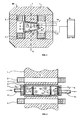
- the basic principle of the present device is illustrated in FIG .
- Seawater desalination takes place in an electric field and in a perpendicularly superimposed magnetic field generated by the electromagnet EM.
- the electromagnet EM consists of a magnetic core 1 and windings 2.
- the windings 2 are made of band capacitor.
- the magnetic core 1 is made of a soft magnetic material such as transformer btech or ferrite.
- transformer plate For frequencies in the range of several kilohertz, highly permeable ferrite, such as manifer, is required.
- an asymmetrical air gap 3 is worked out. The asymmetry is that width A of the air gap 3 is larger than side B.
- Width A should be 50 mm and width B should be 40 mm.
- the cross-sectional areas of the magnetic poles N, S should be on the order of 140 cm 2 .
- an electrolyzer 4 is placed from electrically non-conductive material, in which two discharge electrodes (not shown in Fig. 1 ) arranged and connected by the electrical connections 7 and 8 on the high-frequency generator 9.
- the discharge electrodes in the circuit with the magnet windings 2 through terminals 10, 11 are connected in series to the high-frequency generator 9 .
- drinking water drain 12 is illustrated. Through the outflows 13 and 14 flows out of the electrolyzer, the salt concentrate.
- Fig. 2 illustrates the basic principle of the device illustrated in a cross-section which is parallel to the line I-II (Fig. 1) between which magnetic poles N, S the electrolyzer 4 is arranged, in which electrodes 5 and 6 are fixed.
- the discharge electrodes 5, 6 are, in principle, coated with a good dielectric metal plates.
- the metal plates are the electrical connections 7, 8 to the high frequency generator 9 is connected.
- between the discharge electrodes 5,6 additional components are disposed, such as a plurality of bipolar electrodes 15, Further, the space between the discharge electrodes 5, 6 and the bipolar electrodes 15 is filled with granular granules 16.
- the material of the granules 16 is also a good dielectric such as ceramics of the type: perovskite general chemical formula is Ba (Ti 1 - x Zrx) 03.
- the diameter of the granules is between 6-11 mm and its dielectric constant is between 10,000 and 50,000.
- the discharge electrodes 5 and 6 and bipolar electrodes 15 are also coated with the same or a similar dielectric constant material.
- the seawater is introduced by inflow 17 in the electrolyzer 4 by means of a pump (not shown in Fig. 1 ). Arrow 18 in Fig. 2 shows the direction of flow of seawater. Drinking water drain 12 is attached to the rear of the electrolyzer. At the electrodes 5, 6 and at the bipolar electrodes 15 there are openings 19 through which the seawater flows.
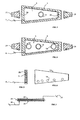
- Fig. 3 shows in section the front view of the electrolyzer 4 with the discharge electrode 5 and the seawater supply 17.
- the discharge electrode 5 is fixed and connected by connection 7 to high-frequency generator 9 .
- fastening parts 21 of the electrolyzer 4 is attached to the structure of the electromagnet EM.
- FIG. 4 shows in section the rear view of the electrolyzer 4.
- the drinking water flows through drains 13, 14 , the salt concentrate flows out of the electrolyzer 4 out.
- Discharge electrode 6 is connected through the electrical connection 8 to high-frequency generator 9 .
- the other symbols in FIG. 4 are the same as in FIG. 3.
- Fig. 5 shows in cross section a discharge electrode 5 which is coated with dielectric 22.
- the dielectric constant should be between 10,000 and 50,000.
- Discharge electrode 5 is connected to high-frequency generator 9 via electrical connection 8 .
- Fig. 6 shows in side view a bipolar electrode 15 with the openings 19 through which the seawater flows.
- the metal plate must be thinly and homogeneously coated on the surface with the high dielectric constant ceramic material. This also counts for the inner walls of the openings 19th
- Fig. 7 shows in section a band capacitor, which consists in principle of two metal foils 23, 24 and dielectric 25 is essential here that an electrical terminal 26 at the beginning of the metal foil 24 and the second electrical terminal 27 is attached to the end of the metal foil 23 .
- the charge and discharge current which is also called wattless current, flows from high-frequency generator 9 through terminal 25 to the metal foil 24 and then as a displacement current through dielectric 25 through metal foil 23 to the electrical terminal 27 , which is also connected to high-frequency generator 9 . That counts for the first half period of the alternating current. In the second half period, the band capacitor is discharged and the entire electric charge flows back to the high frequency generator.
- the wattless current in windings 2 ( Figure 1) produces a magnetic field which for the desalination of seawater according to the invention is the fundamental physical component in the asymmetric gap 3 of the electromagnet EM ( Figure 1) a nonhomogeneous magnetic field.
- the magnetic field strength is greater than on page A. In such an arrangement, one can operate the magnetic field in the air gap at arbitrary frequencies. This is not possible when the windings 2 are wound from wire.
- the following example shows some parameters for the manufacture of the strip capacitor:
- the metal foils 23, 24 (FIG. 7) are made of copper with a thickness of 0.2 mm.
- the width of the metal foils 23 , 24 is 35 mm.
- Dielectric 25 has at least the number one hundred.
- the band capacitor (Fig. 1) is in the DE-OS 199 27 355 A1 described as a novel transformer.
- the capacitive resistance X c ' which is referred to as reactance, is very small at high frequencies and at high capacitances and is defined by equation [2]
- This resistor does not deprive the circuit of energy.
- the electrically charged particles move in the direction according to the principle of magnetic susceptibility pulled the rising magnetic field gradient.
- the force acting on the cations and anions has the dimension of a magnetic dipole moment per unit volume.
- Susceptibility is negative for diamagnetic, negative for substances and positive for paramagnetic substances.
- the accumulation of particles and charges of various cations and anions in the electrolyzer depends on the number and polarity of the susceptibility.
- the paramagnetic, electrically charged particles are pulled in the magnetic field gradient to the side B of the electrolyzer 4 and the dlamagnetic particles are pressed to the side A. This physical phenomenon controls the efficiency of the device described herein.
- the high frequency generator 9 (Fig. 1) supplies alternating current in the electromagnetic circuit at a frequency between 50 Hz and several megahertz.
- a second technical alternative is that the generator 9 provides in the circuit high frequency monopolar pulses.
- the monopulse pulses polarize the dielectric-coated electrodes 5, 6, 15 in one direction, which is of economic importance to the chemical industry and the pharmaceutical industry.
- the device described here consists of one unit, the drinking water in the order of 1,000 1 / h. separated from seawater. Large plants are assembled from a plurality of such units and operated at suitable locations. The operating costs have dropped below 20% compared to the prior art, for which reason the present device for the electromagnetic desalination of seawater is economically advantageous.
Landscapes
- Chemical & Material Sciences (AREA)
- Life Sciences & Earth Sciences (AREA)
- Hydrology & Water Resources (AREA)
- Engineering & Computer Science (AREA)
- Environmental & Geological Engineering (AREA)
- Water Supply & Treatment (AREA)
- Organic Chemistry (AREA)
- Chemical Kinetics & Catalysis (AREA)
- Electrochemistry (AREA)
- General Chemical & Material Sciences (AREA)
- Water Treatment By Electricity Or Magnetism (AREA)
- Separation Using Semi-Permeable Membranes (AREA)
Applications Claiming Priority (2)
| Application Number | Priority Date | Filing Date | Title |
|---|---|---|---|
| DE200610033538 DE102006033538A1 (de) | 2006-07-20 | 2006-07-20 | Vorrichtung zum elektromagnetischen Entsalzen von Meerwasser |
| DE202006011195U DE202006011195U1 (de) | 2006-07-20 | 2006-07-20 | Vorrichtung zum elektromagnetischen Entsalzen von Meerwasser |
Publications (1)
| Publication Number | Publication Date |
|---|---|
| EP1880980A1 true EP1880980A1 (fr) | 2008-01-23 |
Family
ID=38577536
Family Applications (1)
| Application Number | Title | Priority Date | Filing Date |
|---|---|---|---|
| EP07014065A Withdrawn EP1880980A1 (fr) | 2006-07-20 | 2007-07-18 | Dispositif destiné au déssalage électromagnétique d'eau de mer |
Country Status (1)
| Country | Link |
|---|---|
| EP (1) | EP1880980A1 (fr) |
Cited By (5)
| Publication number | Priority date | Publication date | Assignee | Title |
|---|---|---|---|---|
| WO2014183740A1 (fr) * | 2013-05-16 | 2014-11-20 | Pavel Imris | Dispositif de dessalement électromagnétique, en particulier d'eau de mer |
| WO2019229674A1 (fr) * | 2018-05-30 | 2019-12-05 | Khalifa University of Science and Technology | Traitement d'eau salée et d'autres solvants avec des champs magnétiques et électriques |
| CN110980846A (zh) * | 2019-12-23 | 2020-04-10 | 中国船舶重工集团公司第七一九研究所 | 一种电磁能海水淡化装置及方法 |
| CN112062233A (zh) * | 2020-08-28 | 2020-12-11 | 林洪钧 | 一种海水化淡系统 |
| CN114084939A (zh) * | 2022-01-21 | 2022-02-25 | 东营金邦管道工程有限公司 | 超频电脉冲脱盐水处理装置 |
Citations (10)
| Publication number | Priority date | Publication date | Assignee | Title |
|---|---|---|---|---|
| US3207684A (en) * | 1964-12-17 | 1965-09-21 | Jr Walter M Dotts | Method for changing the distribution of ions in a solution of an electrolyte |
| GB1560730A (en) * | 1975-07-16 | 1980-02-06 | Einhell Hans Gmbh | Electrolytic cell for treatment of water |
| EP0065490A1 (fr) | 1981-05-20 | 1982-11-24 | Jenoptik Jena G.m.b.H. | Procédé pour modifier la teneur en sels d'un liquide |
| US4663029A (en) * | 1985-04-08 | 1987-05-05 | Massachusetts Institute Of Technology | Method and apparatus for continuous magnetic separation |
| WO1997023285A1 (fr) * | 1995-12-21 | 1997-07-03 | Philips Electronics N.V. | Procede de traitement de solution aqueuse et dispositif correspondant |
| DE19927355A1 (de) * | 1999-06-16 | 2000-12-21 | Pavel Imris | Transformator mit kapazitivem Widerstand |
| JP2002001391A (ja) * | 2000-06-27 | 2002-01-08 | Kurita Water Ind Ltd | スケール防止方法および装置 |
| DE20317795U1 (de) * | 2003-11-18 | 2004-02-26 | Imris, Pavel, Dr. | Hubmagnet mit Bandkondensator als Erregerwicklung |
| DE202004015611U1 (de) | 2004-10-08 | 2004-12-30 | Imris, Pavel, Dr. | Vorrichtung zum Entsalzen von insbesondere Meerwasser |
| WO2006039873A1 (fr) | 2004-10-08 | 2006-04-20 | Hydrotech International Ltd. | Procede et dispositif pour desaliniser de l'eau de mer a l'aide de champs alternatifs a frequences identiques |
-
2007
- 2007-07-18 EP EP07014065A patent/EP1880980A1/fr not_active Withdrawn
Patent Citations (10)
| Publication number | Priority date | Publication date | Assignee | Title |
|---|---|---|---|---|
| US3207684A (en) * | 1964-12-17 | 1965-09-21 | Jr Walter M Dotts | Method for changing the distribution of ions in a solution of an electrolyte |
| GB1560730A (en) * | 1975-07-16 | 1980-02-06 | Einhell Hans Gmbh | Electrolytic cell for treatment of water |
| EP0065490A1 (fr) | 1981-05-20 | 1982-11-24 | Jenoptik Jena G.m.b.H. | Procédé pour modifier la teneur en sels d'un liquide |
| US4663029A (en) * | 1985-04-08 | 1987-05-05 | Massachusetts Institute Of Technology | Method and apparatus for continuous magnetic separation |
| WO1997023285A1 (fr) * | 1995-12-21 | 1997-07-03 | Philips Electronics N.V. | Procede de traitement de solution aqueuse et dispositif correspondant |
| DE19927355A1 (de) * | 1999-06-16 | 2000-12-21 | Pavel Imris | Transformator mit kapazitivem Widerstand |
| JP2002001391A (ja) * | 2000-06-27 | 2002-01-08 | Kurita Water Ind Ltd | スケール防止方法および装置 |
| DE20317795U1 (de) * | 2003-11-18 | 2004-02-26 | Imris, Pavel, Dr. | Hubmagnet mit Bandkondensator als Erregerwicklung |
| DE202004015611U1 (de) | 2004-10-08 | 2004-12-30 | Imris, Pavel, Dr. | Vorrichtung zum Entsalzen von insbesondere Meerwasser |
| WO2006039873A1 (fr) | 2004-10-08 | 2006-04-20 | Hydrotech International Ltd. | Procede et dispositif pour desaliniser de l'eau de mer a l'aide de champs alternatifs a frequences identiques |
Non-Patent Citations (2)
| Title |
|---|
| FUH C B ET AL: "Magnetic split-flow thin fractionation: new technique for separation of magnetically susceptible particles", JOURNAL OF CHROMATOGRAPHY A, ELSEVIER, AMSTERDAM, NL, vol. 813, no. 2, 17 July 1998 (1998-07-17), pages 313 - 324, XP004129411, ISSN: 0021-9673 * |
| TAKAYASU M ET AL: "DYNAMIC MAGNETIC SEPARATION BY A MAGNETIC SUSCEPTIBILITY DISTRIBUTION", IEEE TRANSACTIONS ON MAGNETICS, IEEE SERVICE CENTER, NEW YORK, NY, US, vol. MAG-20, no. 5, PART 1, September 1984 (1984-09-01), pages 1183 - 1185, XP002026029, ISSN: 0018-9464 * |
Cited By (7)
| Publication number | Priority date | Publication date | Assignee | Title |
|---|---|---|---|---|
| WO2014183740A1 (fr) * | 2013-05-16 | 2014-11-20 | Pavel Imris | Dispositif de dessalement électromagnétique, en particulier d'eau de mer |
| WO2019229674A1 (fr) * | 2018-05-30 | 2019-12-05 | Khalifa University of Science and Technology | Traitement d'eau salée et d'autres solvants avec des champs magnétiques et électriques |
| US11904327B2 (en) | 2018-05-30 | 2024-02-20 | Khalifa University of Science and Technology | Treating saline water and other solvents with magnetic and electric fields |
| CN110980846A (zh) * | 2019-12-23 | 2020-04-10 | 中国船舶重工集团公司第七一九研究所 | 一种电磁能海水淡化装置及方法 |
| CN110980846B (zh) * | 2019-12-23 | 2022-04-29 | 中国船舶重工集团公司第七一九研究所 | 一种电磁能海水淡化装置及方法 |
| CN112062233A (zh) * | 2020-08-28 | 2020-12-11 | 林洪钧 | 一种海水化淡系统 |
| CN114084939A (zh) * | 2022-01-21 | 2022-02-25 | 东营金邦管道工程有限公司 | 超频电脉冲脱盐水处理装置 |
Similar Documents
| Publication | Publication Date | Title |
|---|---|---|
| DE60008931T2 (de) | Automatisierte vorrichtung zur reinigung von trinkwasser | |
| DE68915412T2 (de) | Gas-Flüssigkeitstrennungsverfahren und Vorrichtung für zweiphasige elektroleitende Gas-Flüssigkeitsströme. | |
| AT401739B (de) | Vorrichtung zur aufbereitung von metallhaltigen flüssigkeiten durch ionenaustausch und gleichzeitige oder periodische regenerierung des ionenaustauscherharzes durch elektrodialyse | |
| DE69634516T2 (de) | Nicht verschmutzender durchflusskondensator | |
| DE3238280A1 (de) | Verfahren zum entsalzen von loesungen | |
| DE10332789A1 (de) | Membrananordnung, Elektrodialysevorrichtung und Verfahren zur kontinuierlichen elektrodialytischen Entsalzung | |
| DE3875122T2 (de) | System fuer elektrolytische behandlung einer fluessigkeit. | |
| EP1880980A1 (fr) | Dispositif destiné au déssalage électromagnétique d'eau de mer | |
| EP0337050A1 (fr) | Procédé et appareillage pour la déminéralisation partielle ou totale de l'eau | |
| DE202006011195U1 (de) | Vorrichtung zum elektromagnetischen Entsalzen von Meerwasser | |
| EP1828060A1 (fr) | Procede et dispositif pour desaliner de l'eau de mer a lâide de champs alternatifs a frequences identiques | |
| DE202007009615U1 (de) | Elektrolyseur mit Kondensatorelektroden in einer Magnetfeldpassage zum Entsalzen von Meerwasser | |
| DE202004015611U1 (de) | Vorrichtung zum Entsalzen von insbesondere Meerwasser | |
| EP2014620A2 (fr) | Electrolyseur doté d'électrodes de condensateur dans un passage de champ magnétique destiné à dessaler l'eau de mer | |
| DE2212099C3 (de) | Vorrichtung zur Ruckgewinnung von Metall aus einer Ionen dieses Metalls enthaltenden Flüssigkeit | |
| DE3536778A1 (de) | Elektrodialyse-membranstapeleinheit fuer mehrkammerprozesse | |
| DE2052974C2 (de) | Verfahren zum Reinigen von Wasser und Vorrichtung zu seiner Durchführung | |
| EP0065490A1 (fr) | Procédé pour modifier la teneur en sels d'un liquide | |
| DE102006033538A1 (de) | Vorrichtung zum elektromagnetischen Entsalzen von Meerwasser | |
| WO1989011455A1 (fr) | Procede et dispositif pour conditionner des boues difficilement deshydratables | |
| EP1558527B1 (fr) | Dispositif permettant d'empecher l'entartrage dans des systemes de circulation d'eau | |
| DE102013008403A1 (de) | Vorrichtung zur elektromagnetischen Entsalzung von Meerwasser | |
| DE69613681T2 (de) | Ionisierungseinrichtung für wasserentkeimung und abtrennung von verunreinigungen | |
| DE19832822A1 (de) | Verfahren und Vorrichtung zur kapazitiven Demineralisierung von Ionen enthaltenden Flüssigkeiten | |
| DE202013004613U1 (de) | Vorrichtung zur elektromagnetischen Entsalzung von Meerwasser |
Legal Events
| Date | Code | Title | Description |
|---|---|---|---|
| PUAI | Public reference made under article 153(3) epc to a published international application that has entered the european phase |
Free format text: ORIGINAL CODE: 0009012 |
|
| AK | Designated contracting states |
Kind code of ref document: A1 Designated state(s): AT BE BG CH CY CZ DE DK EE ES FI FR GB GR HU IE IS IT LI LT LU LV MC MT NL PL PT RO SE SI SK TR |
|
| AX | Request for extension of the european patent |
Extension state: AL BA HR MK YU |
|
| AKX | Designation fees paid | ||
| 17P | Request for examination filed |
Effective date: 20081104 |
|
| RBV | Designated contracting states (corrected) |
Designated state(s): AT BE BG CH CY CZ DE DK EE ES FI FR GB GR HU IE IS IT LI LT LU LV MC MT NL PL PT RO SE SI SK TR |
|
| 17Q | First examination report despatched |
Effective date: 20081215 |
|
| STAA | Information on the status of an ep patent application or granted ep patent |
Free format text: STATUS: THE APPLICATION IS DEEMED TO BE WITHDRAWN |
|
| 18D | Application deemed to be withdrawn |
Effective date: 20110201 |