EP2014620A2 - Electrolyseur doté d'électrodes de condensateur dans un passage de champ magnétique destiné à dessaler l'eau de mer - Google Patents
Electrolyseur doté d'électrodes de condensateur dans un passage de champ magnétique destiné à dessaler l'eau de mer Download PDFInfo
- Publication number
- EP2014620A2 EP2014620A2 EP08012445A EP08012445A EP2014620A2 EP 2014620 A2 EP2014620 A2 EP 2014620A2 EP 08012445 A EP08012445 A EP 08012445A EP 08012445 A EP08012445 A EP 08012445A EP 2014620 A2 EP2014620 A2 EP 2014620A2
- Authority
- EP
- European Patent Office
- Prior art keywords
- magnetic field
- electrodes
- electrolyser
- electrolyzer
- electromagnets
- Prior art date
- Legal status (The legal status is an assumption and is not a legal conclusion. Google has not performed a legal analysis and makes no representation as to the accuracy of the status listed.)
- Withdrawn
Links
- 230000005291 magnetic effect Effects 0.000 title claims abstract description 63
- 239000013535 sea water Substances 0.000 title claims abstract description 23
- 150000003839 salts Chemical class 0.000 title claims abstract description 19
- 239000003651 drinking water Substances 0.000 claims abstract description 15
- 235000020188 drinking water Nutrition 0.000 claims abstract description 15
- 239000012141 concentrate Substances 0.000 claims abstract description 7
- 230000003068 static effect Effects 0.000 claims abstract description 6
- FAPWRFPIFSIZLT-UHFFFAOYSA-M Sodium chloride Chemical compound [Na+].[Cl-] FAPWRFPIFSIZLT-UHFFFAOYSA-M 0.000 claims abstract description 4
- 239000004020 conductor Substances 0.000 claims abstract 2
- 230000005294 ferromagnetic effect Effects 0.000 claims abstract 2
- 239000003990 capacitor Substances 0.000 claims description 48
- XLYOFNOQVPJJNP-UHFFFAOYSA-N water Substances O XLYOFNOQVPJJNP-UHFFFAOYSA-N 0.000 claims description 4
- 239000000615 nonconductor Substances 0.000 claims description 3
- 238000010612 desalination reaction Methods 0.000 abstract description 11
- 239000012267 brine Substances 0.000 abstract 1
- 230000010355 oscillation Effects 0.000 abstract 1
- HPALAKNZSZLMCH-UHFFFAOYSA-M sodium;chloride;hydrate Chemical compound O.[Na+].[Cl-] HPALAKNZSZLMCH-UHFFFAOYSA-M 0.000 abstract 1
- 238000000926 separation method Methods 0.000 description 15
- 239000002245 particle Substances 0.000 description 12
- 238000000034 method Methods 0.000 description 7
- 238000011033 desalting Methods 0.000 description 5
- 238000004804 winding Methods 0.000 description 5
- XEEYBQQBJWHFJM-UHFFFAOYSA-N Iron Chemical compound [Fe] XEEYBQQBJWHFJM-UHFFFAOYSA-N 0.000 description 4
- 230000005684 electric field Effects 0.000 description 4
- 239000003792 electrolyte Substances 0.000 description 4
- 230000004907 flux Effects 0.000 description 4
- 230000000630 rising effect Effects 0.000 description 4
- 239000000126 substance Substances 0.000 description 4
- 238000005265 energy consumption Methods 0.000 description 3
- 239000000696 magnetic material Substances 0.000 description 3
- 229910052751 metal Inorganic materials 0.000 description 3
- 239000002184 metal Substances 0.000 description 3
- IJGRMHOSHXDMSA-UHFFFAOYSA-N Atomic nitrogen Chemical compound N#N IJGRMHOSHXDMSA-UHFFFAOYSA-N 0.000 description 2
- RYGMFSIKBFXOCR-UHFFFAOYSA-N Copper Chemical compound [Cu] RYGMFSIKBFXOCR-UHFFFAOYSA-N 0.000 description 2
- PXHVJJICTQNCMI-UHFFFAOYSA-N Nickel Chemical compound [Ni] PXHVJJICTQNCMI-UHFFFAOYSA-N 0.000 description 2
- 238000010276 construction Methods 0.000 description 2
- 230000006735 deficit Effects 0.000 description 2
- 229910052742 iron Inorganic materials 0.000 description 2
- 238000013178 mathematical model Methods 0.000 description 2
- 229910052757 nitrogen Inorganic materials 0.000 description 2
- 230000008569 process Effects 0.000 description 2
- 238000001223 reverse osmosis Methods 0.000 description 2
- 239000011780 sodium chloride Substances 0.000 description 2
- 239000000243 solution Substances 0.000 description 2
- 229910052717 sulfur Inorganic materials 0.000 description 2
- ZOXJGFHDIHLPTG-UHFFFAOYSA-N Boron Chemical compound [B] ZOXJGFHDIHLPTG-UHFFFAOYSA-N 0.000 description 1
- WKBOTKDWSSQWDR-UHFFFAOYSA-N Bromine atom Chemical compound [Br] WKBOTKDWSSQWDR-UHFFFAOYSA-N 0.000 description 1
- OYPRJOBELJOOCE-UHFFFAOYSA-N Calcium Chemical compound [Ca] OYPRJOBELJOOCE-UHFFFAOYSA-N 0.000 description 1
- OKTJSMMVPCPJKN-UHFFFAOYSA-N Carbon Chemical compound [C] OKTJSMMVPCPJKN-UHFFFAOYSA-N 0.000 description 1
- ZAMOUSCENKQFHK-UHFFFAOYSA-N Chlorine atom Chemical compound [Cl] ZAMOUSCENKQFHK-UHFFFAOYSA-N 0.000 description 1
- 229910000531 Co alloy Inorganic materials 0.000 description 1
- PXGOKWXKJXAPGV-UHFFFAOYSA-N Fluorine Chemical compound FF PXGOKWXKJXAPGV-UHFFFAOYSA-N 0.000 description 1
- DGAQECJNVWCQMB-PUAWFVPOSA-M Ilexoside XXIX Chemical compound C[C@@H]1CC[C@@]2(CC[C@@]3(C(=CC[C@H]4[C@]3(CC[C@@H]5[C@@]4(CC[C@@H](C5(C)C)OS(=O)(=O)[O-])C)C)[C@@H]2[C@]1(C)O)C)C(=O)O[C@H]6[C@@H]([C@H]([C@@H]([C@H](O6)CO)O)O)O.[Na+] DGAQECJNVWCQMB-PUAWFVPOSA-M 0.000 description 1
- FYYHWMGAXLPEAU-UHFFFAOYSA-N Magnesium Chemical compound [Mg] FYYHWMGAXLPEAU-UHFFFAOYSA-N 0.000 description 1
- ZOKXTWBITQBERF-UHFFFAOYSA-N Molybdenum Chemical compound [Mo] ZOKXTWBITQBERF-UHFFFAOYSA-N 0.000 description 1
- ZLMJMSJWJFRBEC-UHFFFAOYSA-N Potassium Chemical compound [K] ZLMJMSJWJFRBEC-UHFFFAOYSA-N 0.000 description 1
- NINIDFKCEFEMDL-UHFFFAOYSA-N Sulfur Chemical compound [S] NINIDFKCEFEMDL-UHFFFAOYSA-N 0.000 description 1
- KGWWEXORQXHJJQ-UHFFFAOYSA-N [Fe].[Co].[Ni] Chemical compound [Fe].[Co].[Ni] KGWWEXORQXHJJQ-UHFFFAOYSA-N 0.000 description 1
- 230000009471 action Effects 0.000 description 1
- 229910045601 alloy Inorganic materials 0.000 description 1
- 239000000956 alloy Substances 0.000 description 1
- 150000001450 anions Chemical class 0.000 description 1
- 229910052788 barium Inorganic materials 0.000 description 1
- DSAJWYNOEDNPEQ-UHFFFAOYSA-N barium atom Chemical compound [Ba] DSAJWYNOEDNPEQ-UHFFFAOYSA-N 0.000 description 1
- 230000015572 biosynthetic process Effects 0.000 description 1
- 229910052796 boron Inorganic materials 0.000 description 1
- GDTBXPJZTBHREO-UHFFFAOYSA-N bromine Substances BrBr GDTBXPJZTBHREO-UHFFFAOYSA-N 0.000 description 1
- 229910052794 bromium Inorganic materials 0.000 description 1
- 239000011575 calcium Substances 0.000 description 1
- 229910052791 calcium Inorganic materials 0.000 description 1
- 229910052799 carbon Inorganic materials 0.000 description 1
- 150000001768 cations Chemical class 0.000 description 1
- 239000000460 chlorine Substances 0.000 description 1
- 229910052801 chlorine Inorganic materials 0.000 description 1
- 239000012612 commercial material Substances 0.000 description 1
- 150000001875 compounds Chemical class 0.000 description 1
- 238000004821 distillation Methods 0.000 description 1
- 230000000694 effects Effects 0.000 description 1
- 239000008151 electrolyte solution Substances 0.000 description 1
- 238000005516 engineering process Methods 0.000 description 1
- 239000003302 ferromagnetic material Substances 0.000 description 1
- 239000011737 fluorine Substances 0.000 description 1
- 229910052731 fluorine Inorganic materials 0.000 description 1
- 239000012212 insulator Substances 0.000 description 1
- 239000011777 magnesium Substances 0.000 description 1
- 229910052749 magnesium Inorganic materials 0.000 description 1
- 238000004519 manufacturing process Methods 0.000 description 1
- 239000000463 material Substances 0.000 description 1
- 239000012528 membrane Substances 0.000 description 1
- 238000005272 metallurgy Methods 0.000 description 1
- 229910052750 molybdenum Inorganic materials 0.000 description 1
- 239000011733 molybdenum Substances 0.000 description 1
- 229910052759 nickel Inorganic materials 0.000 description 1
- 239000012811 non-conductive material Substances 0.000 description 1
- 230000003534 oscillatory effect Effects 0.000 description 1
- ZBSCCQXBYNSKPV-UHFFFAOYSA-N oxolead;oxomagnesium;2,4,5-trioxa-1$l^{5},3$l^{5}-diniobabicyclo[1.1.1]pentane 1,3-dioxide Chemical compound [Mg]=O.[Pb]=O.[Pb]=O.[Pb]=O.O1[Nb]2(=O)O[Nb]1(=O)O2 ZBSCCQXBYNSKPV-UHFFFAOYSA-N 0.000 description 1
- 238000005293 physical law Methods 0.000 description 1
- 239000011591 potassium Substances 0.000 description 1
- 229910052700 potassium Inorganic materials 0.000 description 1
- 230000001105 regulatory effect Effects 0.000 description 1
- 239000012266 salt solution Substances 0.000 description 1
- 239000011734 sodium Substances 0.000 description 1
- 229910052708 sodium Inorganic materials 0.000 description 1
- 229910052712 strontium Inorganic materials 0.000 description 1
- CIOAGBVUUVVLOB-UHFFFAOYSA-N strontium atom Chemical compound [Sr] CIOAGBVUUVVLOB-UHFFFAOYSA-N 0.000 description 1
- 239000011593 sulfur Substances 0.000 description 1
- 230000007704 transition Effects 0.000 description 1
- 229910000859 α-Fe Inorganic materials 0.000 description 1
Images
Classifications
-
- C—CHEMISTRY; METALLURGY
- C02—TREATMENT OF WATER, WASTE WATER, SEWAGE, OR SLUDGE
- C02F—TREATMENT OF WATER, WASTE WATER, SEWAGE, OR SLUDGE
- C02F1/00—Treatment of water, waste water, or sewage
- C02F1/46—Treatment of water, waste water, or sewage by electrochemical methods
- C02F1/4604—Treatment of water, waste water, or sewage by electrochemical methods for desalination of seawater or brackish water
-
- C—CHEMISTRY; METALLURGY
- C02—TREATMENT OF WATER, WASTE WATER, SEWAGE, OR SLUDGE
- C02F—TREATMENT OF WATER, WASTE WATER, SEWAGE, OR SLUDGE
- C02F1/00—Treatment of water, waste water, or sewage
- C02F1/48—Treatment of water, waste water, or sewage with magnetic or electric fields
- C02F1/487—Treatment of water, waste water, or sewage with magnetic or electric fields using high frequency electromagnetic fields, e.g. pulsed electromagnetic fields
-
- C—CHEMISTRY; METALLURGY
- C02—TREATMENT OF WATER, WASTE WATER, SEWAGE, OR SLUDGE
- C02F—TREATMENT OF WATER, WASTE WATER, SEWAGE, OR SLUDGE
- C02F1/00—Treatment of water, waste water, or sewage
- C02F1/48—Treatment of water, waste water, or sewage with magnetic or electric fields
- C02F1/484—Treatment of water, waste water, or sewage with magnetic or electric fields using electromagnets
- C02F1/485—Treatment of water, waste water, or sewage with magnetic or electric fields using electromagnets located on the outer wall of the treatment device, i.e. not in contact with the liquid to be treated, e.g. detachable
-
- C—CHEMISTRY; METALLURGY
- C02—TREATMENT OF WATER, WASTE WATER, SEWAGE, OR SLUDGE
- C02F—TREATMENT OF WATER, WASTE WATER, SEWAGE, OR SLUDGE
- C02F2103/00—Nature of the water, waste water, sewage or sludge to be treated
- C02F2103/08—Seawater, e.g. for desalination
-
- C—CHEMISTRY; METALLURGY
- C02—TREATMENT OF WATER, WASTE WATER, SEWAGE, OR SLUDGE
- C02F—TREATMENT OF WATER, WASTE WATER, SEWAGE, OR SLUDGE
- C02F2303/00—Specific treatment goals
- C02F2303/22—Eliminating or preventing deposits, scale removal, scale prevention
Definitions
- the invention relates to an electrolyzer with capacitor electrodes in the magnetic field for the desalination of seawater and for the desalting of salt solutions according to the preamble of claim 1.
- an electrolyzer For the desalination of seawater to drinking water quality, an electrolyzer is used, in which a plurality of capacitor electrodes are arranged and which is fixed in an asymmetric air gap of a magnetic field passage.
- the capacitor electrodes are energized with high frequency current in such a way that in each case two adjacent capacitor electrodes are connected in parallel to the high frequency generator.
- Each capacitor electrode is in the physical principle of an electric double capacitor whose metal plate consists of ferromagnetic material. The distance between the capacitor electrodes is so small that the electrochemical double layer is maximally utilized for the separation of salts. The kinetics of this separation take place in the electrochemical double layer and in the two fields.
- the seawater is an electrolyte and its main components are sodium at 10 mg / l, magnesium at 1,350 mg / l, sulfur at 885 mg / l, potassium at 380 mg / l, calcium at 400 mg / l, strontium at 8 mg / l, iron at 0.01 mg / l, carbon at 28 mg / l, boron at 4.6 mg / l, nitrogen at 15 mg / l, bromine at 65 mg / l, barium at 0.03 mg / l , Chlorine at 19 mg / l, Fluorine at 1.2 mg / l, Molybdenum at 0.01 mg / l and a whole range of other elements whose concentration is less than one hundredth of a milligram per liter.
- the desalination technology focuses mainly on reverse osmosis, on the membrane process, on the thermal process, on the multi-effect distillation, among others.
- the desalination devices mentioned are robust, technically complex, expensive and in all, the energy consumption is enormous. For example, in reverse osmosis energy consumption is between 4 to 5 kWh per 1 square meter of water.
- the global development of desalination capacity is increasing and the demand for drinking water is rising even faster. The development in this field continues and according to the prior art further methods and devices are known.
- the first technically usable device which is operated in a changing magnetic field and simultaneously in a changing electric field, is in the WO 2006 / 039873A1 and in DE-GM 202004 015 611 Ui released. Furthermore, a device for the electromagnetic desalination of seawater in the DE-GM 20 2006 011 195 Ui described.
- the mentioned electromagnetic methods have demonstrated many economic advantages experimentally and the separation of salts between 35% to 50% has been achieved. The deficit of these devices is in the range of electrical current density at the electrodes and bipolar electrodes, which is defined as Ncm 2.
- the already achieved current density is between 0.3 to 0.5 Ncm 2, which is too low. Furthermore, the capacitive current flowing through the metal electrodes is too low and the Faraday Current is too large, resulting in the formation of overcoat on the metal electrodes. It is only feasible to eliminate this deficit if the capacitive current is increased compared to the Faraday current and this at a much higher current density at the electrodes.
- Seawater is an electrolyte solution and therefore it is subject to this rule in an electrolyzer.
- the double-layer capacitance at the electrodes increases to 50 ⁇ F / cm 2.
- this value depends on the current frequency.
- the cited electromagnetic methods are incapable of fully utilizing the double-layer capacitance and therefore one can not improve the separation factor.
- the efficiency at frequencies between 50 Hz and 400 Hz is not more than 50%.
- the invention is therefore an object of the invention to provide an apparatus for performing a method for desalination of seawater, which is operable with a much higher efficiency than in the previous above and thus a drinking water supply is made possible at much lower cost and that the device for Implementation of the desalting constructively requires no great effort and is cheap to maintain.
- the device for carrying out this task consists of an electrolyzer equipped with capacitive current and equipped with mutually spaced-apart capacitor electrodes, which is arranged in an asymmetrical air gap of an electromagnet or permanent magnet.
- the magnetic field is not homogeneous and the magnetic field gradient increases across the width of the electrolyzer.
- the capacitor electrodes are operated with high-frequency current in such a way that a capacitor electrode is connected to one pole of a high frequency generator and the second adjacent is connected to the other pole.
- the third adjacent Capacitor electrode is connected to the same pole as the first capacitor electrode and the fourth capacitor electrode is connected to the same pole as the second, etc.
- the capacitor electrodes are arranged in the electrolyzer at a small distance from each other that the magnetic field acts perpendicular to the electrolytic current.
- the seawater flows in parallel with the longitudinal axis of the electrolyzer around the capacitor electrodes meandering around.
- the cations and the anions receive an amplified magnetic dipole, causing both electrically charged particles to be pulled in the direction of the rising magnetic field gradient.
- the kinetics of the separation of salts of drinking water is directly proportional to the current density at the capacitor electrodes and to the magnetic flux in the air gap of the magnet. As the intensity of both fields increases, the efficiency increases exponentially.
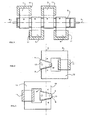
- Fig. 1 in plan view, a plurality of electromagnets in a row, in whose air gap forms a magnetic field passage in which an electrolyzer is arranged.
- FIG. 2 in section, the rear view of an electromagnet, in the asymmetric air gap, an electrolyzer is arranged.
- FIG. 3 in section, the rear view of a second electromagnet, in whose cut in the reverse direction air gap, an electrolyzer is arranged.
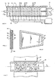
- Fig. 4 in section, the top view of an electrolyzer with capacitor electrodes and electrical circuit.
- Fig. 5 in cross section, a capacitor electrode with capacitor plate and dielectric and two discharge plates.
- Fig. 6 the side view of a capacitor electrode with discharge plate and insulator.
- FIG. 7 in cross-section, an electromagnet with an air gap in which a part of the electrolyzer is arranged.
- the basic principle of the present device is in Fig. 1 illustrated.
- the seawater desalination takes place in an electrolyzer, which is arranged in a magnetic field passage.
- the magnetic field passage consists of a series of electromagnets 1, 2, 3, 4 whose asymmetric air gap is cut so that an asymmetric electrolyzer 5 is pushed in parallel with the imaginary axis 6.
- This construction is in Fig. 2 and Fig. 3 illustrated.
- the air gap 7 on the electromagnet 8 has the shorter side B on the inner side of the electromagnet 8.
- the longer side A is on the outer side of the electromagnet 8.
- Fig. 3 illustrates these design parameters exactly the opposite.
- Gap 9 has the shorter side B on the outside of the electromagnet 10 and the longer side A is on the inner side of the electromagnet.
- the imaginary axis 6 between electromagnets 8 and 10 shows the magnetic field passage between these two.
- the example in Fig. 1 shows, that the device consists of four electromagnets 1, 2, 3, 4, wherein electromagnets 1 and 2 are arranged on one side of the electrolyzer 5 and electromagnets 3 and 4 on the other side.
- the device can be used in Fig. 1 consist of a plurality of electromagnets.
- the magnetic poles of the electromagnets 1, 2, 3, 4 are located close to one another and therefore the entire magnetic field passage forms a balanced magnetic field tunnel.
- Such an arrangement is technically possible because the windings 11 of the adjacent electromagnets are arranged on the other side of the electrolyzer.
- the windings 11 to the electromagnets 1, 2, 3, 4 are energized from band capacitor and with oscillating current.
- the band capacitor is in the DE-OS 199 27 355 A1 described. This is the first application alternative.
- the coils 11 are wound from copper wire and are supplied with direct current.
- the magnetic field is static.
- the magnetic core 12 of all the electromagnets 1, 2, 3, 4 is made of a soft magnetic material, such as e.g. Transformer sheet or a special alloy, for example, from 78% nickel and 22% iron.
- a soft magnetic material such as e.g. Transformer sheet or a special alloy, for example, from 78% nickel and 22% iron.
- highly permeable ferrite such as manifer, is required.
- the cross section of the magnetic core 12 is 50 mm ⁇ 50 mm.
- the asymmetry of the air gap 7 and 9 is 40 mm on the side A and 28 mm on the side B.
- the intensity of the magnetizing current flowing through windings II can be regulated and adjusted as required.
- an electrolyzer 13 is placed from electrically non-conductive material.
- the electrolyzer 13 is illustrated in plan view.
- On the side walls grooves 14 are present in which a plurality of capacitor electrodes 15 is pressed in.
- the capacitor electrodes 15 are connected in parallel to high-frequency generator 18.
- Drains 22, 23, 24 are located on one side of the electrolyzer 13 and their function is to reduce the salt concentrate on the side and thereby keep the concentration gradient low in place.
- the capacitor electrodes 15 in Fig. 4 are close to each other and their distance is between 2 mm and 5 mm.
- the capacitor electrodes 15 should be arranged at a minimum distance from each other, whereby the capacitive electric current between the electrodes is held high.
- capacitor electrode In Fig. 5 the capacitor electrode is illustrated in cross-section. In the middle is capacitor plate 25, which is covered with dielectric 26. Capacitor plate 25 is connected by means of the electrical connection 16 to high-frequency generator 18. On the first outer side of the dielectric 26, a metallic plate electrode 27 is arranged. On the other side of the dielectric 26, a similar metallic plate electrode 28 is attached. The entire components 25, 26, 27, 28 are insulated with electrical insulator 29. Thus produced capacitor electrodes represent the physical principle of a double capacitor, which fulfills a special technical function in the electrolyzer 13.
- Fig. 6 illustrates in side view the in Fig. 5 defined cross section and shows the plate electrodes 27 and the electrical insulator 29.
- the capacitor electrode in Fig. 6 is conically shaped and adapted to the profile of the electrolyzer 13. From a physical point of view, it is important that the capacitor plate 25 be made of soft magnetic material.
- dielectric 26 has a special technical significance and consists of high-quality material, such as perovskites, whose general chemical formula is Ba (Til-x Zr x) 03 or lead magnesium niobate with the formula Pb (M9113 Nb2 / 3) 03. These compounds show no sharp phase transition at the Curie temperature and their dielectric constant is between 10,000 and 50,000.
- Fig. 7 shows in cross section an electromagnet 30 between the poles N, S in air gap 31, a part of electrolyzer 32 is arranged.
- the electrolyzer 32 are in accordance Fig. 4 and FIG. 9 shows capacitor electrodes 33, 34 whose additional physical function is to derive the perpendicular magnetic flux 35 partly in the horizontal direction 36.
- the capacitor plate 25 in Fig. 5 Made of soft magnetic material.
- Such a weak horizontal magnetic flux 36 which is parallel to the electric field 38, has economic significance.
- the horizontal magnetic flux 36 is a physical parameter with the function of increasing the magnetic dipole moment for all charged particles in the electrolyte.
- the electrically charged particles in the horizontal magnetic field 36 and in the horizontal field 38 are forced by known physical law to spiral around the magnetic field lines.
- arrow 37 in FIG Fig. 7 the direction of flow of the electrolyte, which flows around the capacitor electrodes 33, 34 in a meandering manner, which arrow 37 illustrates.
- the capacitor electrodes 33 are fixed to the upper wall and the capacitor electrodes 34 are fixed to the lower wall of the electrolyzer 32.
- the seawater flows, as Arrow 37 illustrates, through the gaps between the electrodes and the Eletkrolyseurwand.
- the electrically charged particles are drawn in the direction of the rising magnetic field gradient according to the principle of a magnetic dipole moment.
- the dipole moment depends on the specific electrical charge of each charged particle. Particles with a larger specific electric charge are pulled with greater force in the direction of the increasing magnetic field gradient than particles with a low specific charge. That's the rule that determines this selective separation.
- the particles in the electrolyte are set in oscillatory motion by a large electric current density and by a large current frequency.
- the current density at the plate electrode 27 in Fla. 6 to 8 Ncm2 is adjustable. This is ten times what can be achieved in the prior art.
- electric current flows through the electrolyzer at a very high frequency an even greater current density can be achieved after the Debye-Falkenhagen effect.
- the difference in specific charge of each particle increases, thereby increasing the selective separation of the salt particles.
- This rule has wide validity and a physical limit is unknown. A mathematical model to define this rule is complicated and outside the text described here.
- the present device is technically straightforward, easy to manufacture and the entire construction consists of commercial materials.
- the device is operated by various physical parameters that are specifically adjustable for specific saline solutions. For example, the device is operated at different current frequencies and that between 50 Hz and 300 kHz. When the device is operated at 10 kHz, the magnetic cores of all the electromagnets are made of nickel-iron-cobalt alloy, and the thickness of the sheets is between 1 mm and 2 mm. In this technical embodiment, current flows through the electrolyzer at the same frequency as the magnetizing current which oscillates in the band capacitor windings 11.
- Fig. 1 illustrates a fundamental unit consisting of four electromagnets 1, 2, 3, 4.
- the frequencies for both electrical currents are adjustable between 1 kHz and 7 kHz and the current density at the electrode plates 27 is 5 Ncm 2.
- Such a unit is technically capable of desalting the seawater to 0.05% by weight. Economical is of importance, the electrical energy consumption of such a unit is less than 2 kWh / 1 .000 1 water.
- the unit in Fig. 1 can be extended with other electromagnets.
- the number of electromagnets is sufficient.
- the separation factor in the electrolyzer 13 in Fig. 4 is negatively affected by the concentration gradient. Because the salt separation already takes place at the first capacitor electrode and increases with each additional capacitor electrode 15, it is necessary that the outflows 22, 23, 24 in Fig. 4 are arranged on the side of the electrolyzer 13. Due to the mentioned outflows, the salt concentrate is continuously reduced.
- the present device is also used in specific areas of the economy and operated at a current frequency of more than 100 kHz. If by the electrolyzer 13 in Fig. 4 electric current flows at such frequency, then the product of current and area is a magnetic dipole moment whose vectorial direction changes rapidly. In such an electrochemical environment, the charged particles are always pulled in the direction of the rising magnetic field gradient, regardless of whether the external magnetic field oscillates or is static. According to this rule, the electromagnets 1, 2, 3, 4 are magnetized with direct current and the windings 11 are then wound from copper wire. Technically, this means that in the entire magnetic field passage a static magnetic field causes the separation of charged particles. In such a static magnetic field passage, the separation factor is enormous and the separation efficiency is very economical.
- the device described here consists of one unit with a drinking water capacity of approx. 1,000 l / h.
- the length of the unit is selected as required.
- Large drinking water systems are assembled from a plurality of such units and operated at suitable locations. The operating costs are compared to the prior art only at 20% and therefore the device described here is economically advantageous.
Landscapes
- Chemical & Material Sciences (AREA)
- Organic Chemistry (AREA)
- Life Sciences & Earth Sciences (AREA)
- Hydrology & Water Resources (AREA)
- Engineering & Computer Science (AREA)
- Environmental & Geological Engineering (AREA)
- Water Supply & Treatment (AREA)
- Electrochemistry (AREA)
- General Chemical & Material Sciences (AREA)
- Chemical Kinetics & Catalysis (AREA)
- Physics & Mathematics (AREA)
- Electromagnetism (AREA)
- Water Treatment By Electricity Or Magnetism (AREA)
- Separation Using Semi-Permeable Membranes (AREA)
Applications Claiming Priority (1)
| Application Number | Priority Date | Filing Date | Title |
|---|---|---|---|
| DE200710031977 DE102007031977A1 (de) | 2007-07-10 | 2007-07-10 | Elektrolyseur mit Kondensatorelektroden in einer Magnetfeldpassage zum Entsalzen von Meerwasser |
Publications (2)
| Publication Number | Publication Date |
|---|---|
| EP2014620A2 true EP2014620A2 (fr) | 2009-01-14 |
| EP2014620A3 EP2014620A3 (fr) | 2013-10-30 |
Family
ID=39864984
Family Applications (1)
| Application Number | Title | Priority Date | Filing Date |
|---|---|---|---|
| EP08012445.6A Withdrawn EP2014620A3 (fr) | 2007-07-10 | 2008-07-10 | Electrolyseur doté d'électrodes de condensateur dans un passage de champ magnétique destiné à dessaler l'eau de mer |
Country Status (2)
| Country | Link |
|---|---|
| EP (1) | EP2014620A3 (fr) |
| DE (1) | DE102007031977A1 (fr) |
Cited By (4)
| Publication number | Priority date | Publication date | Assignee | Title |
|---|---|---|---|---|
| DE202013004613U1 (de) | 2013-05-16 | 2013-06-28 | Pavel Imris | Vorrichtung zur elektromagnetischen Entsalzung von Meerwasser |
| WO2014183740A1 (fr) | 2013-05-16 | 2014-11-20 | Pavel Imris | Dispositif de dessalement électromagnétique, en particulier d'eau de mer |
| EP3542632A4 (fr) * | 2016-11-17 | 2020-07-15 | Duvoisin, Charles Adriano | Système et procédé de neutralisation de produits agrotoxiques ou d'agents similaires contenus dans des aliments, et agencement structural pour leur mixe eu oeuvre |
| CN118122141A (zh) * | 2024-05-07 | 2024-06-04 | 北京大学 | 一种膜分离装置及方法 |
Citations (4)
| Publication number | Priority date | Publication date | Assignee | Title |
|---|---|---|---|---|
| DE19927355A1 (de) | 1999-06-16 | 2000-12-21 | Pavel Imris | Transformator mit kapazitivem Widerstand |
| DE202004015611U1 (de) | 2004-10-08 | 2004-12-30 | Imris, Pavel, Dr. | Vorrichtung zum Entsalzen von insbesondere Meerwasser |
| WO2006039873A1 (fr) | 2004-10-08 | 2006-04-20 | Hydrotech International Ltd. | Procede et dispositif pour desaliniser de l'eau de mer a l'aide de champs alternatifs a frequences identiques |
| DE202006011195U1 (de) | 2006-07-20 | 2006-09-28 | Imris, Pavel, Dr. | Vorrichtung zum elektromagnetischen Entsalzen von Meerwasser |
Family Cites Families (3)
| Publication number | Priority date | Publication date | Assignee | Title |
|---|---|---|---|---|
| US3207684A (en) * | 1964-12-17 | 1965-09-21 | Jr Walter M Dotts | Method for changing the distribution of ions in a solution of an electrolyte |
| FR2063605A5 (en) * | 1969-10-23 | 1971-07-09 | Chabanier Bernard | Separation of ions from an ionised liquid |
| EP0065490A1 (fr) * | 1981-05-20 | 1982-11-24 | Jenoptik Jena G.m.b.H. | Procédé pour modifier la teneur en sels d'un liquide |
-
2007
- 2007-07-10 DE DE200710031977 patent/DE102007031977A1/de not_active Withdrawn
-
2008
- 2008-07-10 EP EP08012445.6A patent/EP2014620A3/fr not_active Withdrawn
Patent Citations (4)
| Publication number | Priority date | Publication date | Assignee | Title |
|---|---|---|---|---|
| DE19927355A1 (de) | 1999-06-16 | 2000-12-21 | Pavel Imris | Transformator mit kapazitivem Widerstand |
| DE202004015611U1 (de) | 2004-10-08 | 2004-12-30 | Imris, Pavel, Dr. | Vorrichtung zum Entsalzen von insbesondere Meerwasser |
| WO2006039873A1 (fr) | 2004-10-08 | 2006-04-20 | Hydrotech International Ltd. | Procede et dispositif pour desaliniser de l'eau de mer a l'aide de champs alternatifs a frequences identiques |
| DE202006011195U1 (de) | 2006-07-20 | 2006-09-28 | Imris, Pavel, Dr. | Vorrichtung zum elektromagnetischen Entsalzen von Meerwasser |
Cited By (6)
| Publication number | Priority date | Publication date | Assignee | Title |
|---|---|---|---|---|
| DE202013004613U1 (de) | 2013-05-16 | 2013-06-28 | Pavel Imris | Vorrichtung zur elektromagnetischen Entsalzung von Meerwasser |
| WO2014183740A1 (fr) | 2013-05-16 | 2014-11-20 | Pavel Imris | Dispositif de dessalement électromagnétique, en particulier d'eau de mer |
| DE102013008403A1 (de) | 2013-05-16 | 2014-11-20 | Pavel Imris | Vorrichtung zur elektromagnetischen Entsalzung von Meerwasser |
| EP3542632A4 (fr) * | 2016-11-17 | 2020-07-15 | Duvoisin, Charles Adriano | Système et procédé de neutralisation de produits agrotoxiques ou d'agents similaires contenus dans des aliments, et agencement structural pour leur mixe eu oeuvre |
| CN118122141A (zh) * | 2024-05-07 | 2024-06-04 | 北京大学 | 一种膜分离装置及方法 |
| WO2025232303A1 (fr) * | 2024-05-07 | 2025-11-13 | 北京大学 | Appareil et procédé de séparation par membrane |
Also Published As
| Publication number | Publication date |
|---|---|
| EP2014620A3 (fr) | 2013-10-30 |
| DE102007031977A1 (de) | 2009-01-15 |
Similar Documents
| Publication | Publication Date | Title |
|---|---|---|
| DE68915412T2 (de) | Gas-Flüssigkeitstrennungsverfahren und Vorrichtung für zweiphasige elektroleitende Gas-Flüssigkeitsströme. | |
| DE69831134T2 (de) | Behandlung von wasser | |
| DE69318693T2 (de) | Magnetischer Konditionierer zur Behandlung von Flüssigkeiten | |
| DE3124599A1 (de) | "verfahren und vorrichtung zum zerstaeuben mit magnetischer verstaerkung sowie zur beschichtung eines substrats" | |
| DE2707144A1 (de) | Kathodenzerstaeubungsvorrichtung | |
| DE2802689A1 (de) | Verfahren zur durchfuehrung eines elektrolyseprozesses | |
| DE10332789A1 (de) | Membrananordnung, Elektrodialysevorrichtung und Verfahren zur kontinuierlichen elektrodialytischen Entsalzung | |
| DE3012935C2 (de) | Zerstäubungsvorrichtung mit magnetischer Verstärkung | |
| DE202007009615U1 (de) | Elektrolyseur mit Kondensatorelektroden in einer Magnetfeldpassage zum Entsalzen von Meerwasser | |
| DE102012014266A1 (de) | Magnetisch-induktives Durchflussmessgerät | |
| EP2327665A1 (fr) | Dispositif de dessalement au moyen de membranes sélectives et de champs magnétiques | |
| WO2006039873A1 (fr) | Procede et dispositif pour desaliniser de l'eau de mer a l'aide de champs alternatifs a frequences identiques | |
| DE102007031977A1 (de) | Elektrolyseur mit Kondensatorelektroden in einer Magnetfeldpassage zum Entsalzen von Meerwasser | |
| EP1880980A1 (fr) | Dispositif destiné au déssalage électromagnétique d'eau de mer | |
| EP0337050A1 (fr) | Procédé et appareillage pour la déminéralisation partielle ou totale de l'eau | |
| DE2920780C2 (de) | Zerstäubungsvorrichtung mit magnetischer Verstärkung | |
| DE2850783C2 (de) | Verfahren zum Steuern der Überzugsdicke von mit flüssigen metallbeschichteten Metallsubstraten und Vorrichtung zur Durchführung dieses Verfahrens | |
| DE202004015611U1 (de) | Vorrichtung zum Entsalzen von insbesondere Meerwasser | |
| DE202006011195U1 (de) | Vorrichtung zum elektromagnetischen Entsalzen von Meerwasser | |
| DE2361154A1 (de) | Vorrichtung zur multipolaren magnetisierung | |
| DE2212099C3 (de) | Vorrichtung zur Ruckgewinnung von Metall aus einer Ionen dieses Metalls enthaltenden Flüssigkeit | |
| DE3536778A1 (de) | Elektrodialyse-membranstapeleinheit fuer mehrkammerprozesse | |
| DE3741584A1 (de) | Elektromagnetischer stroemungsmesser mit alternierendem permanentmagnetfeld | |
| EP0065490A1 (fr) | Procédé pour modifier la teneur en sels d'un liquide | |
| DE102013008403A1 (de) | Vorrichtung zur elektromagnetischen Entsalzung von Meerwasser |
Legal Events
| Date | Code | Title | Description |
|---|---|---|---|
| PUAI | Public reference made under article 153(3) epc to a published international application that has entered the european phase |
Free format text: ORIGINAL CODE: 0009012 |
|
| AK | Designated contracting states |
Kind code of ref document: A2 Designated state(s): AT BE BG CH CY CZ DE DK EE ES FI FR GB GR HR HU IE IS IT LI LT LU LV MC MT NL NO PL PT RO SE SI SK TR |
|
| AX | Request for extension of the european patent |
Extension state: AL BA MK RS |
|
| RAP1 | Party data changed (applicant data changed or rights of an application transferred) |
Owner name: SCHILDGEN, MORITZ Owner name: IMRIS, PAVEL DR. |
|
| RIN1 | Information on inventor provided before grant (corrected) |
Inventor name: SCHILDGEN, MORITZ Inventor name: IMRIS, PAVEL DR. |
|
| PUAL | Search report despatched |
Free format text: ORIGINAL CODE: 0009013 |
|
| AK | Designated contracting states |
Kind code of ref document: A3 Designated state(s): AT BE BG CH CY CZ DE DK EE ES FI FR GB GR HR HU IE IS IT LI LT LU LV MC MT NL NO PL PT RO SE SI SK TR |
|
| AX | Request for extension of the european patent |
Extension state: AL BA MK RS |
|
| RIC1 | Information provided on ipc code assigned before grant |
Ipc: C02F 1/48 20060101ALI20130920BHEP Ipc: C02F 1/46 20060101AFI20130920BHEP Ipc: C02F 103/08 20060101ALN20130920BHEP Ipc: C02F 1/461 20060101ALI20130920BHEP |
|
| STAA | Information on the status of an ep patent application or granted ep patent |
Free format text: STATUS: THE APPLICATION IS DEEMED TO BE WITHDRAWN |
|
| AKY | No designation fees paid | ||
| REG | Reference to a national code |
Ref country code: DE Ref legal event code: R108 |
|
| 18D | Application deemed to be withdrawn |
Effective date: 20140201 |
|
| REG | Reference to a national code |
Ref country code: DE Ref legal event code: R108 Effective date: 20140709 |