EP1881125A1 - Élément de renforcement, procédé pour sa fabrication et élément de construction pourvu d'un tel élément de renforcement - Google Patents
Élément de renforcement, procédé pour sa fabrication et élément de construction pourvu d'un tel élément de renforcement Download PDFInfo
- Publication number
- EP1881125A1 EP1881125A1 EP06117647A EP06117647A EP1881125A1 EP 1881125 A1 EP1881125 A1 EP 1881125A1 EP 06117647 A EP06117647 A EP 06117647A EP 06117647 A EP06117647 A EP 06117647A EP 1881125 A1 EP1881125 A1 EP 1881125A1
- Authority
- EP
- European Patent Office
- Prior art keywords
- reinforcing element
- element according
- component
- profile
- anchoring part
- Prior art date
- Legal status (The legal status is an assumption and is not a legal conclusion. Google has not performed a legal analysis and makes no representation as to the accuracy of the status listed.)
- Ceased
Links
- 230000003014 reinforcing effect Effects 0.000 title claims abstract description 121
- 238000004519 manufacturing process Methods 0.000 title claims abstract description 15
- 238000000034 method Methods 0.000 title claims abstract description 15
- 239000000835 fiber Substances 0.000 claims abstract description 19
- 229920002748 Basalt fiber Polymers 0.000 claims abstract description 3
- 239000004760 aramid Substances 0.000 claims abstract description 3
- 229920006231 aramid fiber Polymers 0.000 claims abstract description 3
- 239000002657 fibrous material Substances 0.000 claims abstract description 3
- 239000011521 glass Substances 0.000 claims abstract description 3
- 238000004873 anchoring Methods 0.000 claims description 38
- 239000000463 material Substances 0.000 claims description 10
- 238000010438 heat treatment Methods 0.000 claims description 7
- 230000001070 adhesive effect Effects 0.000 claims description 6
- 230000008569 process Effects 0.000 claims description 6
- 239000000853 adhesive Substances 0.000 claims description 5
- 239000011159 matrix material Substances 0.000 claims description 5
- 229920001169 thermoplastic Polymers 0.000 claims description 5
- 239000004416 thermosoftening plastic Substances 0.000 claims description 5
- OKTJSMMVPCPJKN-UHFFFAOYSA-N Carbon Chemical compound [C] OKTJSMMVPCPJKN-UHFFFAOYSA-N 0.000 claims description 3
- 229910052799 carbon Inorganic materials 0.000 claims description 3
- 239000004917 carbon fiber Substances 0.000 claims description 3
- 239000011347 resin Substances 0.000 claims description 3
- 229920005989 resin Polymers 0.000 claims description 3
- 229920000049 Carbon (fiber) Polymers 0.000 claims description 2
- 238000000748 compression moulding Methods 0.000 claims description 2
- 238000007731 hot pressing Methods 0.000 claims description 2
- 238000003475 lamination Methods 0.000 claims description 2
- 238000000465 moulding Methods 0.000 claims description 2
- 238000003856 thermoforming Methods 0.000 claims description 2
- 229920001187 thermosetting polymer Polymers 0.000 claims description 2
- 230000001154 acute effect Effects 0.000 abstract 2
- 239000003245 coal Substances 0.000 abstract 1
- 230000002787 reinforcement Effects 0.000 description 10
- 238000010276 construction Methods 0.000 description 8
- 230000008901 benefit Effects 0.000 description 6
- 239000004918 carbon fiber reinforced polymer Substances 0.000 description 6
- 239000002131 composite material Substances 0.000 description 6
- 229920002430 Fibre-reinforced plastic Polymers 0.000 description 5
- 229910000831 Steel Inorganic materials 0.000 description 5
- 239000011151 fibre-reinforced plastic Substances 0.000 description 5
- 239000010959 steel Substances 0.000 description 5
- 238000001816 cooling Methods 0.000 description 4
- 239000010410 layer Substances 0.000 description 4
- 230000006641 stabilisation Effects 0.000 description 4
- 238000011105 stabilization Methods 0.000 description 4
- 238000012545 processing Methods 0.000 description 3
- 230000000087 stabilizing effect Effects 0.000 description 3
- 150000001875 compounds Chemical class 0.000 description 2
- 230000000694 effects Effects 0.000 description 2
- 239000004744 fabric Substances 0.000 description 2
- 239000003365 glass fiber Substances 0.000 description 2
- 239000004033 plastic Substances 0.000 description 2
- 229920003023 plastic Polymers 0.000 description 2
- 239000011150 reinforced concrete Substances 0.000 description 2
- 239000007858 starting material Substances 0.000 description 2
- 230000006978 adaptation Effects 0.000 description 1
- 230000032683 aging Effects 0.000 description 1
- 238000013459 approach Methods 0.000 description 1
- 230000007797 corrosion Effects 0.000 description 1
- 238000005260 corrosion Methods 0.000 description 1
- 230000006735 deficit Effects 0.000 description 1
- 238000013461 design Methods 0.000 description 1
- 238000011161 development Methods 0.000 description 1
- 230000018109 developmental process Effects 0.000 description 1
- 239000011152 fibreglass Substances 0.000 description 1
- 239000012467 final product Substances 0.000 description 1
- 230000006872 improvement Effects 0.000 description 1
- 238000002955 isolation Methods 0.000 description 1
- 239000007788 liquid Substances 0.000 description 1
- 230000003287 optical effect Effects 0.000 description 1
- 230000008092 positive effect Effects 0.000 description 1
- 238000009417 prefabrication Methods 0.000 description 1
- 239000002994 raw material Substances 0.000 description 1
- 239000002356 single layer Substances 0.000 description 1
- 239000007787 solid Substances 0.000 description 1
- 230000035882 stress Effects 0.000 description 1
- 230000007704 transition Effects 0.000 description 1
- 238000010792 warming Methods 0.000 description 1
- 238000004804 winding Methods 0.000 description 1
Images


Classifications
-
- E—FIXED CONSTRUCTIONS
- E04—BUILDING
- E04G—SCAFFOLDING; FORMS; SHUTTERING; BUILDING IMPLEMENTS OR AIDS, OR THEIR USE; HANDLING BUILDING MATERIALS ON THE SITE; REPAIRING, BREAKING-UP OR OTHER WORK ON EXISTING BUILDINGS
- E04G23/00—Working measures on existing buildings
- E04G23/02—Repairing, e.g. filling cracks; Restoring; Altering; Enlarging
- E04G23/0218—Increasing or restoring the load-bearing capacity of building construction elements
-
- E—FIXED CONSTRUCTIONS
- E04—BUILDING
- E04C—STRUCTURAL ELEMENTS; BUILDING MATERIALS
- E04C5/00—Reinforcing elements, e.g. for concrete; Auxiliary elements therefor
- E04C5/07—Reinforcing elements of material other than metal, e.g. of glass, of plastics, or not exclusively made of metal
-
- E—FIXED CONSTRUCTIONS
- E04—BUILDING
- E04G—SCAFFOLDING; FORMS; SHUTTERING; BUILDING IMPLEMENTS OR AIDS, OR THEIR USE; HANDLING BUILDING MATERIALS ON THE SITE; REPAIRING, BREAKING-UP OR OTHER WORK ON EXISTING BUILDINGS
- E04G23/00—Working measures on existing buildings
- E04G23/02—Repairing, e.g. filling cracks; Restoring; Altering; Enlarging
- E04G23/0218—Increasing or restoring the load-bearing capacity of building construction elements
- E04G2023/0251—Increasing or restoring the load-bearing capacity of building construction elements by using fiber reinforced plastic elements
Definitions
- the invention relates to a reinforcing element, as it can be used preferably for stabilizing and reinforcing components on buildings, a method for producing such a reinforcing element and a component equipped with a reinforcing element.
- Reinforcing elements of the type in question here are on the one hand in a new building of considerable importance, for example, to ensure the seismic safety of the building.
- older buildings can be retrofitted with such reinforcing elements, because a component to be reinforced, for example, due to excessive stresses damage that must be corrected.
- materials with high tensile strength for the reinforcement of components.
- fiber-reinforced plastics are particularly suitable. These have in addition to the high tensile strength mentioned also a very low weight and are easy to handle.
- fiber-reinforced plastics can be processed very easily. Subsequent reinforcement of reinforced concrete is thus possible without difficulty.
- CFRP materials Carbon fiber-reinforced plastics (CFRP materials), for example, can be used in lamellar form for the transverse reinforcement of bridges, for increasing the payload of ceilings and for stiffening wooden structures. Columns and pillars are also secured with CFRP laminates only a few millimeters thick.
- the subsequent steel reinforcement of components in the construction sector is characterized by a very complex production. Furthermore, this sometimes results in considerable corrosion problems. Due to the relatively high weight of a steel reinforcement, the applications are difficult, that is, the adaptation to the component is not readily possible. In addition, optical impairments result from such steel reinforcements, which are undesirable for certain components of buildings.
- this reinforcing structure consists of a plurality of adhesive strips of glass fiber lamellae, which are crosswise bonded together and one above the other.
- the objective pursued in this document is to stabilize the transitional area between two components in contact with one another, such as, for example, a beam and a column connected to this beam.
- the WO 98/53150 A1 relates to a stabilization of the composite region of two contacting components to buildings.
- the fiber reinforced plastics crosswise or at an angle of 90 ° or at angles between 15 ° to 60 ° relative to the Wrapped in the longitudinal direction of the component to be reinforced and thus reinforced.
- the fibers may also be unidirectional and in multiple layers. It is essential to realize that bonding of reinforcing members to carbon fiber reinforced plastics is currently known in the construction industry. It is also known to wrap transition areas between components that contact one another by such materials and thus to achieve a stabilizing effect. So far, however, no solutions are in use that stabilize the component itself and in a simple way, a sustainable improvement in the durability of, for example, a structure, a part of a structure or a beam allow.
- the invention has for its object to provide a material-efficient and thus cost-effective reinforcing element for reinforcing components, which effectively stabilizes the component as such, which is easy to retrofit and can be used on existing components in buildings as well as on newly created structures.
- a method is provided which allows the production of such a reinforcing element.
- a reinforcing element which consists of a fiber-reinforced profile and has a forming region through which the reinforcing element at an angle of 45 ° ⁇ 5 ° with respect to the longitudinal extent of the component to be reinforced on the corresponding component can be applied ,
- the reinforcing element according to the invention can be brought into the desired shape by a forming process before it is attached to the component.
- a reinforcing element is available, which can be placed directly on the component to be amplified and connected to this.
- the fiber is hardly loaded and stretched by the forming process, so that pre-damage within the reinforcing element can be effectively avoided.
- the reinforcing element acts like a free tension member without composite. It can be used both to prevent fractures of components in the construction sector, as well as to protect these components as a precaution from damage due to adjusting aging processes.
- the reinforcing element according to the invention makes it possible to increase the load capacity of the components equipped with this reinforcing element.
- the reinforcing element can be used flexibly and can be provided without great effort on the components to be reinforced.
- the reinforcing element can be prefabricated, the production cost is not incurred in the construction phase, so not on site on the building, so that this results in the construction phase considerable time and cost advantages.
- the profile may be a flat profile, a U-profile, a T-profile or an L-profile according to an embodiment of the invention. Decisive for the choice of the profile is only the strength to be achieved by means of the reinforcing element and the adaptability to the component to be reinforced.
- a component in the context of the present invention are in particular structures, parts of structures or beams to be understood as parts of buildings in the construction sector.
- the said beams are provided on reinforced concrete ceilings, bridge girders, for example in the longitudinal and / or transverse direction and serve, for example, the reinforcement of wall outbreaks or wall openings.
- a reinforcing element according to the invention can be used when displacing falls, such as window or door lintels.
- the diversity of the present applications also shows the possibilities of choosing different cross-sections of such a component. So it may have a polygonal or cycloid cross sections.
- the reinforcing element at an angle of 45 ° ⁇ 5 ° with respect to the longitudinal extent attachable and thus meets the general inventive concept.
- the reinforcing element can have an anchoring part at least at one of its ends. This anchoring part serves for additional attachment of the reinforcing element to the component to be reinforced.
- the anchoring part starting from the cross section of the profile, proceed into a polygonal or cycloidal cross section.
- the anchoring part has a polygonal or cycloidal cross-section.
- the anchoring part is made Stationaryrig. Multi-limbed here means that the end of the anchoring part is divided into individual segments or sections or in the simplest case has at least one recess. This can be used, for example, to receive a fastener or to guide such a fastener through the thus formed openings or recesses.
- the anchoring part has a geometry suitable for receiving or carrying out a fastening element.
- a fastener may represent a dowel, a screw, a rivet or a similar means. This must only be suitable to produce a detachable or permanently fixed connection between the reinforcing element and the component to be reinforced in the region of the anchoring part.
- the anchoring part can be inserted into a recess of the component.
- a cohesive connection can be, for example, an adhesive connection. If the reinforcing element is produced from thermoplastic or duroplastic matrix resin, then this is liquid in the raw state and solidifies at or after the processing. The matrix resin is applied to the component to be reinforced and integrally bonds to it by hardening. The connection thus created is weather-resistant and corresponds to the requirements placed on the component to be reinforced.
- the reinforcing element is formed by high-modulus carbon fibers, wherein the fiber direction of the reinforcing element can be unidirectionally aligned.
- an FRP element Fiber Reinforced-Profile element
- the reinforcing element is a FRP tension element or an FRP shear angle.
- the reinforcing element consists in particular of carbon, glass, aramid or basalt fiber material with a high Exa value and high tensile strength.
- the prefabrication of the reinforcing element in the sense of the aforementioned method has the advantages that a fiber-conserving processing of the fiber composite material is possible. Thus, no damage to the profile and this meets in comparison with known solutions significantly higher strength requirements. Thus, higher stabilization effects of the component to be reinforced can be achieved, as is the case with known embodiments.
- At least one anchoring part is formed on at least one end of the reinforcing element.
- the Anformung can be done in one or more consecutive steps.
- the anchoring part is worked out directly from the reinforcing element. This results in a uniform fabric structure, which has an overall positive effect on the strength values of the reinforcing element.
- a particularly advantageous possibility of use of a reinforcing element according to the invention can be specified for a supporting structure, a structural part or a beam of a building.
- a component with a reinforcing element according to the invention is the subject of the invention, wherein the reinforcing element is attached to the component at an angle of 45 ° ⁇ 5 ° relative to the longitudinal extent of the component.
- Reinforcing element and component are integrally connected to each other according to an embodiment of this component.
- the cohesive connection can be produced by the adhesive effect inherent in the fiber-reinforced plastic or a separate adhesive material.
- a component according to the invention with a reinforcing element is also characterized in that the reinforcing element has at least one anchoring part provided on the reinforcing element and a connection between the reinforcing element and the component is formed via this anchoring part by means of a fastening element.
- This compound can be a detachable or permanently solid compound.
- the component with the reinforcing element has at least one anchoring part provided on the reinforcing element, which can be inserted into a recess of the component.
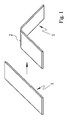
- FIG. 1 shows a stage plan for producing a first embodiment of a reinforcing element according to the invention.
- a profile 1 produced as a flat profile is produced from a so-called prepreg based on thermoplastic or thermosetting matrices.
- the fiber course is preferably unidirectional in such a component.
- the profile 1 shown has a forming region 2, which results from a local short-term heating.
- a locally limited section can be changed in its material properties to thereby produce the 45 ° inclined FRP profile.
- the individual layers of the prepreg can be stacked discontinuously or continuously one above the other and pressed together under the influence of temperature and pressure or formed into a one-piece component. If a warming has taken place, a final cooling is necessary.
- thermoplastic flat profiles should be mentioned as starting materials, which are heated only in the intended range of curvature and converted accordingly.
- the height of the heating temperature is adjusted so that the plastic matrix can soften locally and for a limited time, wherein the softening state can take place in a liquefaction region.
- After the forming of the flat profile to the inclined by 45 ° FRP shear angle is a brief cooling, so that the profile 1 remains in its final position and can be applied directly to the component to be amplified.
- FIG. 2 Another variant for producing a reinforcing element according to the invention is shown in detail as a stadium plan in Figure 2 .
- As starting materials for this 45 ° FRP shear angle with a reshaped Anchoring part 4 are preferably used unidirectionally reinforced thermoplastic round profiles, which have the same cross-sectional area as the final product. Such round profiles are heated again with the exception of the anchoring part and pressed into a flat profile.
- the profile 1 in the left part of Figure 2 represents the round profile as a blank and the profile 1 in the middle of Figure 2, the already pressed flat profile with the still undeformed anchoring part 4.
- the reinforcing element according to the invention as a whole can also be produced from two individual round profiles 1.1 and 1.2. Different approaches are available.
- a further variant is also to convert the original round profiles 1.1 and 1.2 by a suitably suitable forming process in a flat profile 1.
- a heating can be provided.
- the anchoring part 4 has a circular cross-section.
- this anchoring part 4 was again bent in relation to the profile 1, which was already reshaped in FIG. 4 in the area of the forming region 2, so that a multi-curved profile 1 results. That is, here the profile 1 has a second forming region 2, which was not designated in detail in Figure 4, on.
- FIG. 5 An application for the present invention is shown by way of example in FIG . 5 .
- This is a component 3, which in the present case consists of a simple, rectangular in cross-section bars, provided with a reinforcing element according to the invention.
- the reinforcing element consists of the profile 1 and two anchoring parts 4.1 and 4.2. These anchoring parts 4.1 and 4.2 are introduced in the embodiment shown in recesses of the component 3 and anchored therein.
- the profile 1 in each case has an angle ⁇ of 45 ° ⁇ 5 ° with respect to the longitudinal extent of the component 3 to be reinforced. Said angle refers in each case to the longitudinal extension of the side surface provided with the reinforcing element of the component 3 to be reinforced.
Landscapes
- Engineering & Computer Science (AREA)
- Architecture (AREA)
- Civil Engineering (AREA)
- Structural Engineering (AREA)
- Chemical & Material Sciences (AREA)
- Chemical Kinetics & Catalysis (AREA)
- Electrochemistry (AREA)
- Mechanical Engineering (AREA)
- Moulding By Coating Moulds (AREA)
- Reinforced Plastic Materials (AREA)
- Electrical Discharge Machining, Electrochemical Machining, And Combined Machining (AREA)
Priority Applications (5)
| Application Number | Priority Date | Filing Date | Title |
|---|---|---|---|
| EP06117647A EP1881125A1 (fr) | 2006-07-21 | 2006-07-21 | Élément de renforcement, procédé pour sa fabrication et élément de construction pourvu d'un tel élément de renforcement |
| PCT/EP2007/057524 WO2008009744A1 (fr) | 2006-07-21 | 2007-07-20 | élément de renfort, procédé de fabrication d'un tel élément de renfort et composant doté d'un élément de renfort |
| DE502007003614T DE502007003614D1 (de) | 2006-07-21 | 2007-07-20 | Verstärkungselement, verfahren zur herstellung eines derartigen verstärkungselementes und bauteil, ausgestattet mit einem verstärkungselement |
| AT07787774T ATE466149T1 (de) | 2006-07-21 | 2007-07-20 | Verstärkungselement, verfahren zur herstellung eines derartigen verstärkungselementes und bauteil, ausgestattet mit einem verstärkungselement |
| EP07787774A EP2047046B1 (fr) | 2006-07-21 | 2007-07-20 | Élément de renfort, procédé de fabrication d'un tel élément de renfort et composant doté d'un élément de renfort |
Applications Claiming Priority (1)
| Application Number | Priority Date | Filing Date | Title |
|---|---|---|---|
| EP06117647A EP1881125A1 (fr) | 2006-07-21 | 2006-07-21 | Élément de renforcement, procédé pour sa fabrication et élément de construction pourvu d'un tel élément de renforcement |
Publications (1)
| Publication Number | Publication Date |
|---|---|
| EP1881125A1 true EP1881125A1 (fr) | 2008-01-23 |
Family
ID=37527758
Family Applications (2)
| Application Number | Title | Priority Date | Filing Date |
|---|---|---|---|
| EP06117647A Ceased EP1881125A1 (fr) | 2006-07-21 | 2006-07-21 | Élément de renforcement, procédé pour sa fabrication et élément de construction pourvu d'un tel élément de renforcement |
| EP07787774A Active EP2047046B1 (fr) | 2006-07-21 | 2007-07-20 | Élément de renfort, procédé de fabrication d'un tel élément de renfort et composant doté d'un élément de renfort |
Family Applications After (1)
| Application Number | Title | Priority Date | Filing Date |
|---|---|---|---|
| EP07787774A Active EP2047046B1 (fr) | 2006-07-21 | 2007-07-20 | Élément de renfort, procédé de fabrication d'un tel élément de renfort et composant doté d'un élément de renfort |
Country Status (4)
| Country | Link |
|---|---|
| EP (2) | EP1881125A1 (fr) |
| AT (1) | ATE466149T1 (fr) |
| DE (1) | DE502007003614D1 (fr) |
| WO (1) | WO2008009744A1 (fr) |
Cited By (1)
| Publication number | Priority date | Publication date | Assignee | Title |
|---|---|---|---|---|
| FR2948712A1 (fr) * | 2009-08-03 | 2011-02-04 | Soletanche Freyssinet | Procede de renforcement d'une structure de construction, et ouvrage ainsi renforce |
Citations (6)
| Publication number | Priority date | Publication date | Assignee | Title |
|---|---|---|---|---|
| US4020202A (en) * | 1973-07-07 | 1977-04-26 | Maschinenfabrik Augsburg-Nurnberg Ag | Beam and strut girder |
| JPH11293788A (ja) * | 1998-04-06 | 1999-10-26 | Mitsui Home Co Ltd | 住宅部材の接合構造及びその接合方法 |
| WO2001051736A1 (fr) * | 2000-01-13 | 2001-07-19 | Dow Global Technologies Inc. | Composites a base de resines thermoplastiques et de fibres renforcantes comme supports de structure externe |
| US6324805B1 (en) * | 1999-03-17 | 2001-12-04 | Fukuvi Chemical Industry Co., Ltd. | Structural reinforcement system and reinforcing method at joint between structural members |
| JP2005105685A (ja) * | 2003-09-30 | 2005-04-21 | Nippon Oil Corp | L字状繊維強化樹脂プレート及びそれを用いた構造物補強方法 |
| JP2005219365A (ja) * | 2004-02-06 | 2005-08-18 | Toray Ind Inc | 繊維強化プラスチック板および建築構造物 |
Family Cites Families (1)
| Publication number | Priority date | Publication date | Assignee | Title |
|---|---|---|---|---|
| EP1549810A1 (fr) * | 2002-09-25 | 2005-07-06 | The University Of Southern Queensland | Elements structuraux formes de materiaux moulables |
-
2006
- 2006-07-21 EP EP06117647A patent/EP1881125A1/fr not_active Ceased
-
2007
- 2007-07-20 DE DE502007003614T patent/DE502007003614D1/de not_active Expired - Fee Related
- 2007-07-20 AT AT07787774T patent/ATE466149T1/de active
- 2007-07-20 WO PCT/EP2007/057524 patent/WO2008009744A1/fr not_active Ceased
- 2007-07-20 EP EP07787774A patent/EP2047046B1/fr active Active
Patent Citations (6)
| Publication number | Priority date | Publication date | Assignee | Title |
|---|---|---|---|---|
| US4020202A (en) * | 1973-07-07 | 1977-04-26 | Maschinenfabrik Augsburg-Nurnberg Ag | Beam and strut girder |
| JPH11293788A (ja) * | 1998-04-06 | 1999-10-26 | Mitsui Home Co Ltd | 住宅部材の接合構造及びその接合方法 |
| US6324805B1 (en) * | 1999-03-17 | 2001-12-04 | Fukuvi Chemical Industry Co., Ltd. | Structural reinforcement system and reinforcing method at joint between structural members |
| WO2001051736A1 (fr) * | 2000-01-13 | 2001-07-19 | Dow Global Technologies Inc. | Composites a base de resines thermoplastiques et de fibres renforcantes comme supports de structure externe |
| JP2005105685A (ja) * | 2003-09-30 | 2005-04-21 | Nippon Oil Corp | L字状繊維強化樹脂プレート及びそれを用いた構造物補強方法 |
| JP2005219365A (ja) * | 2004-02-06 | 2005-08-18 | Toray Ind Inc | 繊維強化プラスチック板および建築構造物 |
Cited By (3)
| Publication number | Priority date | Publication date | Assignee | Title |
|---|---|---|---|---|
| FR2948712A1 (fr) * | 2009-08-03 | 2011-02-04 | Soletanche Freyssinet | Procede de renforcement d'une structure de construction, et ouvrage ainsi renforce |
| EP2295675A1 (fr) * | 2009-08-03 | 2011-03-16 | Soletanche Freyssinet | Procede de renforcement d'une structure de construction, et ouvrage ainsi renforce |
| US8925268B2 (en) | 2009-08-03 | 2015-01-06 | Soletanche Freyssinet | Process for reinforcing a construction structure, and structure thus reinforced |
Also Published As
| Publication number | Publication date |
|---|---|
| EP2047046B1 (fr) | 2010-04-28 |
| ATE466149T1 (de) | 2010-05-15 |
| EP2047046A1 (fr) | 2009-04-15 |
| DE502007003614D1 (de) | 2010-06-10 |
| WO2008009744A1 (fr) | 2008-01-24 |
Similar Documents
| Publication | Publication Date | Title |
|---|---|---|
| EP0906480B1 (fr) | Element structural | |
| EP3057774B1 (fr) | Pièce munie d'une partie fixation permettant un assemblage par vis et pièce moulée et élément de fixation | |
| DE19619212A1 (de) | Wagenkasten eines Schienenfahrzeuges | |
| EP3695062A1 (fr) | Élément d'ancrage, pièce en béton pourvue d'un élément d'ancrage et procédé de fabrication | |
| DE2757965A1 (de) | Schubuebertragungselement und verfahren zu dessen herstellung | |
| DE3432905A1 (de) | Verfahren zur verminderung der rissbildung von langgestreckten hohlkoerpern ... | |
| EP2419325A2 (fr) | Membrure et procédé de fabrication d'une telle membrure | |
| DE102014000316B4 (de) | Verbundbauteil aus auf Stahlträgern aufgelagerten Deckenbetonfertigteilen | |
| EP2352887A1 (fr) | Elements de construction pour batiments | |
| DE102011017460A1 (de) | Faserverbundbauteil, Flügelspitzenverlängerung und Flugzeug mit einem Faserverbundteil | |
| EP3656553A1 (fr) | Matériau composite renforcé par des fibres | |
| EP2707530B1 (fr) | Structure textile de renfort multicouche intégrant une matrice thermoplastique pour la fabrication de structures composites semi-finies formables et renforcées par des fibres | |
| EP2047046B1 (fr) | Élément de renfort, procédé de fabrication d'un tel élément de renfort et composant doté d'un élément de renfort | |
| DE102012019905B3 (de) | Rumpfstrukturbauteil für Fahrzeuge, insbesondere für Luft- und/oder Raumfahrzeuge | |
| DE2700089A1 (de) | Kraftschluessige verbindung von bauelementen | |
| DE102011054275A1 (de) | Kragplattenanschlusselement | |
| DE102016124226A1 (de) | Gitterträger für Betontragwerke | |
| EP3705657B1 (fr) | Structure de renfort textile pour un composant, procédé de fabrication pour une structure de renfort, composant et pièce semi-finie | |
| DE2616294A1 (de) | Mehrschichtenplatte oder -schale aus kunststoff | |
| DE2727458C2 (de) | Verbund-Bauteil aus Kunststoff-Hartschaum | |
| DE4003207A1 (de) | Fachwerk aus fertigteilen | |
| DE10310896A1 (de) | Bewehrungselement für den Betonbau | |
| EP3730708B1 (fr) | Élément de raccordement thermo-isolant et composant thermo-isolant | |
| AT520486B1 (de) | Bewehrungsmaterial | |
| EP1512804A2 (fr) | Procédé pour la fabrication d'un mur d'une construction |
Legal Events
| Date | Code | Title | Description |
|---|---|---|---|
| PUAI | Public reference made under article 153(3) epc to a published international application that has entered the european phase |
Free format text: ORIGINAL CODE: 0009012 |
|
| AK | Designated contracting states |
Kind code of ref document: A1 Designated state(s): AT BE BG CH CY CZ DE DK EE ES FI FR GB GR HU IE IS IT LI LT LU LV MC NL PL PT RO SE SI SK TR |
|
| AX | Request for extension of the european patent |
Extension state: AL BA HR MK YU |
|
| STAA | Information on the status of an ep patent application or granted ep patent |
Free format text: STATUS: THE APPLICATION HAS BEEN REFUSED |
|
| 18R | Application refused |
Effective date: 20071122 |