EP1882531A2 - Procédé et installation destinés au nettoyage de canaux d'aération pourvus de corps d'aération en plastique - Google Patents
Procédé et installation destinés au nettoyage de canaux d'aération pourvus de corps d'aération en plastique Download PDFInfo
- Publication number
- EP1882531A2 EP1882531A2 EP07405167A EP07405167A EP1882531A2 EP 1882531 A2 EP1882531 A2 EP 1882531A2 EP 07405167 A EP07405167 A EP 07405167A EP 07405167 A EP07405167 A EP 07405167A EP 1882531 A2 EP1882531 A2 EP 1882531A2
- Authority
- EP
- European Patent Office
- Prior art keywords
- air
- ventilation duct
- ventilation
- cleaning arrangement
- cleaning
- Prior art date
- Legal status (The legal status is an assumption and is not a legal conclusion. Google has not performed a legal analysis and makes no representation as to the accuracy of the status listed.)
- Withdrawn
Links
Images

Classifications
-
- B—PERFORMING OPERATIONS; TRANSPORTING
- B08—CLEANING
- B08B—CLEANING IN GENERAL; PREVENTION OF FOULING IN GENERAL
- B08B9/00—Cleaning hollow articles by methods or apparatus specially adapted thereto
- B08B9/02—Cleaning pipes or tubes or systems of pipes or tubes
- B08B9/027—Cleaning the internal surfaces; Removal of blockages
- B08B9/032—Cleaning the internal surfaces; Removal of blockages by the mechanical action of a moving fluid, e.g. by flushing
- B08B9/0321—Cleaning the internal surfaces; Removal of blockages by the mechanical action of a moving fluid, e.g. by flushing using pressurised, pulsating or purging fluid
-
- B—PERFORMING OPERATIONS; TRANSPORTING
- B08—CLEANING
- B08B—CLEANING IN GENERAL; PREVENTION OF FOULING IN GENERAL
- B08B5/00—Cleaning by methods involving the use of air flow or gas flow
- B08B5/02—Cleaning by the force of jets, e.g. blowing-out cavities
-
- B—PERFORMING OPERATIONS; TRANSPORTING
- B08—CLEANING
- B08B—CLEANING IN GENERAL; PREVENTION OF FOULING IN GENERAL
- B08B9/00—Cleaning hollow articles by methods or apparatus specially adapted thereto
- B08B9/02—Cleaning pipes or tubes or systems of pipes or tubes
- B08B9/027—Cleaning the internal surfaces; Removal of blockages
- B08B9/032—Cleaning the internal surfaces; Removal of blockages by the mechanical action of a moving fluid, e.g. by flushing
- B08B9/035—Cleaning the internal surfaces; Removal of blockages by the mechanical action of a moving fluid, e.g. by flushing by suction
Definitions
- the invention relates to a method for cleaning ventilation ducts provided with plastic ventilation bodies according to the preamble of claim 1 and a cleaning arrangement for ventilation ducts provided with ventilation bodies made of plastic according to the preamble of claim 13.
- Ventilation of the type in question are usually made of a reinforced plastic, in particular a glass fiber reinforced plastic such as polypropylene or polyethylene.
- the ventilation body itself is generally formed relatively thin-walled and defined in its interior the actually ventilation duct or the ventilation ducts.
- Such ventilation bodies are used, for example, in dashboards of motor vehicles by distributing the air to be blown into the interior of the vehicle to different outlet openings.
- the ventilation bodies usually consist of two semi-shells produced by injection molding or die casting, which are sealed together. To join these shells, friction or high-frequency welding processes, in particular vibration welding processes, are increasingly being used. Friction welding processes are so-called hot-press welding processes in which the heating of the firmly clamped parts to be joined together takes place by mechanical friction.
- the friction is usually generated by a relative movement between the two parts to be joined under force without additional material.
- the result is a welding bead typical for the process.
- the relative movement is canceled and the two parts to be joined together under pressure.
- a disadvantage of such Reibschweissclar is that due to the relative movement of the two parts to be joined an abrasion in the form of small plastic particles, which are optionally also mixed with glass fibers arises. Of course, such particles also accumulate within the ventilation bodies in the ventilation ducts.
- An additional disadvantage is that the plastic from which such ventilation body are made and / or the abrasion during the friction welding and / or during the cooling electrostatically charges, resulting in an electrostatic adhesion of the mentioned particles on the walls of the ventilation ducts leads.
- a method and apparatus for blowing out hollow plastic preforms by ionized air wherein the preforms to be cleaned have a hemispherically closed lower end and an open upper end.
- Said device consists of a holder to which a tube for blowing air is fixed on the underside. The end of this tube forms a blowing nozzle, wherein an ionization electrode is fixed in the mouth region of the tuyere. The ionization electrode is connected to a high voltage generator.
- a suction channel is provided, by means of which the air emerging from the respective preform can be sucked off.
- the invention aims to develop a method for cleaning ventilation ducts made of plastic ventilation bodies according to the preamble of claim 1 such that the located in the ventilation ducts particles, in particular in the friction or high-frequency welding in the form of Plastic particles accumulate abrasion quickly, easily and safely remove or leaves.
- the invention further aims to develop a cleaning arrangement for ventilation ducts provided with ventilation ducts made of plastic according to the preamble of claim 13 such that the ventilation ducts can be cleaned quickly, easily and safely, in particular by the resulting in friction or high-frequency welding abrasion in the Form of plastic particles is removed.
- the static charge causing the adhesion of the particles can be neutralized.
- the particles located in the respective ventilation channel in particular also the plastic particles produced during the welding process, can be removed from the respective ventilation channel easily, quickly and safely.
- the arrangement 1 has a pneumatic device 2 and an electrical device 3.
- the pneumatic device 2 comprises a compressed air source 5, a solenoid valve 6, a filter unit 7, and two nozzle bodies 8, 9.
- the electrical device 3 consists of an electrical power supply 11, an electronic controller 12, a rotary knob 13, a high voltage power supply 14, an electrical Distribution block 15, a sensor S and two ionizer tips 17, 18, of which one in each of the two nozzle body 8, 9 is arranged. It is understood that more than one ionizer tip can be provided per nozzle body 8, 9.
- the arrangement 1 is also provided with at least one suction device (not shown), which is connected on the outlet side to the ventilation duct or ventilation duct section to be cleaned.
- the filter unit 7 comprises in addition to the actual filter a pressure gauge and a regulator and is used to clean the air.
- the compressed air source 5 is connected via a pneumatic line to the solenoid valve 6, the latter via the electronic control 12 of the electrical part 3 is actuated, i. opened and closed.
- the solenoid valve 6 thus acts as a pneumatic on-off switch for the compressed air.
- the solenoid valve 6 When the solenoid valve 6 is open, the air supplied by the compressed air source 5 flows via the solenoid valve 6 into the filter unit 7, where it is cleaned and regulated in the pressure.
- the output of the filter unit 7 is connected via a respective line with a nozzle body 8, 9.
- the respective nozzle body 8, 9 is provided with a plurality of outlet nozzles (not shown), via which the compressed air, as indicated by arrows P1, P2, can escape.
- the power source 11 supplies the high-voltage power supply 14 with electrical energy
- the control 12 arranged between the power source 11 and the high-voltage power supply 14 serving, inter alia, as an on-off switch.
- the mains voltage which is usually between 110 and 240V and has a frequency of 50-60 Hz, is transformed to approximately 4000-7000V.
- the controller 12 is turned on, on the one hand the magnetic switch 6 is opened and on the other hand the high-voltage power supply 14 is supplied with energy.
- the Distribution block 15 the high voltage to the two ionizer tips 17, 18 split.
- the distribution block 15 is connected via a respective line with the respective ionizer tip 17, 18.
- the air flowing past the respective ionizer tip 17, 18 is ionized by generating both positively and negatively charged ions.
- the rotary controller 13 connected to the electronic control unit 12 may be designed, for example, as a potentiometer and serves to change the proportion between positively and negatively charged ions.
- the residual charge of the component -ventilation body cleaned by means of ionized air- is measured after the actual cleaning process.
- the measurement of the residual charge can be done for example by means of a field strength meter.
- On the basis of the measured residual charge of the component it is then decided whether the proportion of positively or negatively charged ions should be increased, which is achieved by corresponding rotation of the rotary knob.
- the measurement of the residual charge of the purified by ionized air component is preferably carried out at certain intervals, with constant ambient conditions usually no appreciable changes in the residual charge of the component can be expected. However, if, for example, the temperature or the humidity changes, there may well be changes. You may also expect changes from batch to batch.
- the air supplied to the respective nozzle body 8, 9 after switching on the control 12 exits via one or more nozzles from the nozzle body 8, 9, whereby it is previously guided past the respective ionizer tip 17, 18 in the nozzle body 8, 9 that the electric field generated by the high voltage causes the ionization of the air.
- the ionization of the air preferably does not take place in the mouth region, but the air is preferably conducted past the respective ionizer tip at a distance of about 8-15 mm.
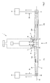
- FIG. 2 shows, in a further simplified representation, the cleaning arrangement 1 according to FIG. 1 in an application example.
- a schematically illustrated ventilation body 19 can be seen as it can be used in a dashboard of a motor vehicle, for example a car.
- the two shells 20, 21 are made of a glass fiber reinforced plastic, such as polypropylene or polyethylene.
- the weld seam 22 produced during the friction welding process, by means of which the two shells 20, 21 are tightly connected, is indicated schematically.
- the symmetrically designed ventilation body 19 consists of a left half 23a and a right half 23b, in the interior of each of which the actual ventilation duct 24a, 24b extends.
- the ventilation body 19 or the respective ventilation duct 24a, 24b is provided with two central inflow openings 26, 27 and two lateral outflow openings 28, 29.
- a nozzle body 8, 9 is arranged above the central inflow opening 26, 27 of the respective ventilation duct 24a, 24b.
- the respective nozzle body 8, 9 is designed such that it covers the respective inflow opening 26, 27 and thus closes.
- the respective nozzle body 8, 9 is formed as a kind of cover, by means of which the respective inflow opening 26, 27 can be completely closed.
- the ionized air supplied via the respective nozzle body 8, 9 is forcibly passed through the respective ventilation duct 24a, 24b and can not escape upwardly in part via the inflow opening 26, 27.
- At the two outflow openings 28, 29 each have a suction device 30, 31 is connected, which also favors a uniform flow through the air.
- ionized air is injected obliquely into the two ventilation channels 24a, 24b via the two nozzle bodies 8, 9, which is indicated by the arrows P1, P2.
- the injected air as indicated by arrows 32, 33, is sucked off via the respective suction device 30, 31 at the two outflow openings 28, 29.
- the respective suction device 30, 31 has two functions, on the one hand ensuring that the air is passed through the respective ventilation duct 24a, 24b at a constant speed. On the other hand separates the respective suction device 30, 31 in the air entrained plastic particles and any other impurities.
- the ionized air consists of freely movable positively and negatively charged ions, which cause the adhesion of the particles causing electrostatic charge is neutralized.
- the two ventilation channels 24a, 24b are freed of the abrasion generated during the welding process in the form of small plastic particles.
- the ratio between positively and negatively charged ions can possibly be changed so that, if necessary, an even more efficient purification can be achieved.
- the two to be cleaned ventilation ducts 24a, 24b each have a cross section of about 25cm second
- ionized air is passed through the respective ventilation duct 24a, 24b at a speed of about 5-15 meters / second for about 3-5 seconds.
- the air used has a water vapor content of about 6 g / m 3 at a dew point of 3 ° C.
- the air used is largely oil-free and contains no dust particles that are larger than 5 microns.
- the processing of the air in this regard can be done either by the filter unit or by an external device.
- the cleaning assembly is used directly on the welding station, where the respective ventilation body is welded.
- the cleaning process can be started immediately after the welding of the ventilation body.
- it is sufficient to conduct ionized air at a speed of approx. 5 to 15 meters / second for a few seconds through the respective ventilation duct so that it is thoroughly freed from the plastic particles accumulating during the welding process.
- both the Flow rate of the air, as well as the duration of the cleaning process can be adapted to the particular circumstances. In this respect, previous information should not be regarded as binding.
- the cleaning arrangement can be clocked so that the manufacturing process of the ventilation body is not significantly delayed even in mass production.
- Ventilation bodies for use in dashboards of motor vehicles
- inventive method and the corresponding arrangement can of course also be used for cleaning provided with ventilation ducts ventilation bodies, which, for example, for use in rail vehicles, ships, aircraft or in space Air conditioners are provided.
Landscapes
- Engineering & Computer Science (AREA)
- Mechanical Engineering (AREA)
- Lining Or Joining Of Plastics Or The Like (AREA)
- Elimination Of Static Electricity (AREA)
- Cleaning In General (AREA)
- Duct Arrangements (AREA)
Applications Claiming Priority (1)
| Application Number | Priority Date | Filing Date | Title |
|---|---|---|---|
| CH12232006 | 2006-07-27 |
Publications (2)
| Publication Number | Publication Date |
|---|---|
| EP1882531A2 true EP1882531A2 (fr) | 2008-01-30 |
| EP1882531A3 EP1882531A3 (fr) | 2009-08-05 |
Family
ID=37587344
Family Applications (1)
| Application Number | Title | Priority Date | Filing Date |
|---|---|---|---|
| EP07405167A Withdrawn EP1882531A3 (fr) | 2006-07-27 | 2007-06-11 | Procédé et installation destinés au nettoyage de canaux d'aération pourvus de corps d'aération en plastique |
Country Status (1)
| Country | Link |
|---|---|
| EP (1) | EP1882531A3 (fr) |
Cited By (4)
| Publication number | Priority date | Publication date | Assignee | Title |
|---|---|---|---|---|
| DE102008062378A1 (de) * | 2008-12-17 | 2010-07-08 | Khs Ag | Verfahren und Vorrichtung zur Behandlung von Behältern |
| DE102018120693A1 (de) * | 2018-08-24 | 2020-02-27 | Joma-Polytec Gmbh | Verfahren zur Reinigung von Bauteilen, insbesondere von medienführenden Bauteilen |
| EP3736357A1 (fr) | 2019-05-07 | 2020-11-11 | Dr.Ing. Max Schlötter GmbH & Co. KG | Procédé de sulfonation de matières plastiques pour la métallisation chimique à l'aide du so3 et du so2 |
| CN119121212A (zh) * | 2024-09-06 | 2024-12-13 | 西安热工研究院有限公司 | 激光熔覆用粉料覆盖装置及其操作方法 |
Family Cites Families (2)
| Publication number | Priority date | Publication date | Assignee | Title |
|---|---|---|---|---|
| DE3711777A1 (de) * | 1987-04-08 | 1988-10-27 | Claus G Dipl Ing Wandres | Verfahren und vorrichtung zum entstauben von folien o. dgl. |
| DE10140906B4 (de) * | 2001-08-21 | 2004-02-12 | Krones Ag | Verfahren und Vorrichtung zum Ausblasen von Vorformlingen aus Kunststoff |
-
2007
- 2007-06-11 EP EP07405167A patent/EP1882531A3/fr not_active Withdrawn
Cited By (8)
| Publication number | Priority date | Publication date | Assignee | Title |
|---|---|---|---|---|
| DE102008062378A1 (de) * | 2008-12-17 | 2010-07-08 | Khs Ag | Verfahren und Vorrichtung zur Behandlung von Behältern |
| US8834640B2 (en) | 2008-12-17 | 2014-09-16 | Khs Gmbh | Method and device for treating containers |
| DE102018120693A1 (de) * | 2018-08-24 | 2020-02-27 | Joma-Polytec Gmbh | Verfahren zur Reinigung von Bauteilen, insbesondere von medienführenden Bauteilen |
| CN110856852A (zh) * | 2018-08-24 | 2020-03-03 | 悦马塑料技术有限公司 | 用于清洁部件、尤其是引导介质的部件的方法 |
| DE102018120693B4 (de) | 2018-08-24 | 2024-05-23 | Joma-Polytec Gmbh | Verfahren zur Reinigung von medienführenden Kunststoffbauteilen |
| EP3736357A1 (fr) | 2019-05-07 | 2020-11-11 | Dr.Ing. Max Schlötter GmbH & Co. KG | Procédé de sulfonation de matières plastiques pour la métallisation chimique à l'aide du so3 et du so2 |
| WO2020225052A1 (fr) | 2019-05-07 | 2020-11-12 | Dr.-Ing. Max Schlötter Gmbh & Co. Kg | Procédé pour la sulfonation de matières plastiques pour la métallisation chimique avec so3 et so2 |
| CN119121212A (zh) * | 2024-09-06 | 2024-12-13 | 西安热工研究院有限公司 | 激光熔覆用粉料覆盖装置及其操作方法 |
Also Published As
| Publication number | Publication date |
|---|---|
| EP1882531A3 (fr) | 2009-08-05 |
Similar Documents
| Publication | Publication Date | Title |
|---|---|---|
| EP2830779B1 (fr) | Dispositif de nettoyage à la neige carbonique et procédé associé à une installation de peinture | |
| EP1214154A2 (fr) | Procede et dispositif de fabrication d'une couche protectrice amovible pour des surfaces, en particulier des surfaces vernies de vehicules motorises | |
| DE19535557B4 (de) | Verfahren und Vorrichtung zum Reinigen einer Innenwandung einer Form mittels Trockeneis | |
| EP3072638A1 (fr) | Ébavurage de pièces moulées, en particulier de pièces moulées en caoutchouc | |
| DE102016200522A1 (de) | Verfahren zur Herstellung dreidimensionaler Objekte und Vorrichtung zur Durchführung des besagten Verfahrens | |
| EP1882531A2 (fr) | Procédé et installation destinés au nettoyage de canaux d'aération pourvus de corps d'aération en plastique | |
| DE1786277A1 (de) | Vorrichtung zum elektrostatischen Entladen von laufenden Materialbahnen und deren gleichzeitiger Entstaubung | |
| DE20321726U1 (de) | Vorrichtung zur Beseitigung von Luftverunreinigungen in einer Nasslackieranlage | |
| DE102017003661A1 (de) | Kunststoffformgebungsverfahren und Formgebungsmaschine | |
| EP4005758A1 (fr) | Dispositif et procédé de revêtement d'une pièce | |
| EP3359337B1 (fr) | Procédé servant à nettoyer des surfaces de collage au moyen de dioxyde de carbone solide | |
| EP4263298A1 (fr) | Dispositif de nettoyage, système de nettoyage et de détection pour un véhicule et véhicule et procédé permettant de nettoyer une surface d'un capteur qui doit être nettoyée | |
| WO2015106778A1 (fr) | Dispositif d'introduction pour diffuser un parfum et/ou de l'air ionisé dans l'habitacle d'un véhicule | |
| DE102016004857A1 (de) | Verfahren zum Reinigen der Luft eines Fahrgastraums eines Fahrzeugs | |
| EP2467210A2 (fr) | Dispositif d'aspiration | |
| DE102015219429A1 (de) | Verfahren zum Reinigen mithilfe von festem Kohlenstoffdioxid | |
| DE10007143B4 (de) | Runderneuerungsverfahren | |
| EP2368642B1 (fr) | Dispositif d'aération pour installations de laquage par pulvérisation | |
| DE102010045428A1 (de) | Verfahren und Vorrichtung zum Transport eines Faserstranges aus Verbundwerkstoff | |
| EP2149449B1 (fr) | Procédé et dispositif de fabrication d'un composant composite doté d'un élément de support pouvant fondre ou se ramollir et d'une pièce rapportée, notamment un filtre d'entrée d'air de véhicule automobile | |
| EP0306842B1 (fr) | Procédé et appareil pour appliquer une feuille en matière plastique fondue sur une surface de refroidissement en mouvement | |
| EP1509342A1 (fr) | Dispositif de nettoyage a sec de pieces | |
| EP3551401B1 (fr) | Procédé d'introduction d'un fluide d'application dans une fissure d'affaiblissement d'un élément de recouvrement ainsi que système d'application préféré | |
| DE10309674B4 (de) | Konturgenaues Bedampfen von mit einem textilen Gewebe überzogenen Kunststoffformteilen zur Verbesserung der textilen Oberfläche | |
| EP1187733A1 (fr) | Dispositif de regulation de la temperature a l'interieur d'un vehicule |
Legal Events
| Date | Code | Title | Description |
|---|---|---|---|
| PUAI | Public reference made under article 153(3) epc to a published international application that has entered the european phase |
Free format text: ORIGINAL CODE: 0009012 |
|
| AK | Designated contracting states |
Kind code of ref document: A2 Designated state(s): AT BE BG CH CY CZ DE DK EE ES FI FR GB GR HU IE IS IT LI LT LU LV MC MT NL PL PT RO SE SI SK TR |
|
| AX | Request for extension of the european patent |
Extension state: AL BA HR MK YU |
|
| PUAL | Search report despatched |
Free format text: ORIGINAL CODE: 0009013 |
|
| AK | Designated contracting states |
Kind code of ref document: A3 Designated state(s): AT BE BG CH CY CZ DE DK EE ES FI FR GB GR HU IE IS IT LI LT LU LV MC MT NL PL PT RO SE SI SK TR |
|
| AX | Request for extension of the european patent |
Extension state: AL BA HR MK RS |
|
| 17P | Request for examination filed |
Effective date: 20090819 |
|
| AKX | Designation fees paid |
Designated state(s): AT BE BG CH CY CZ DE DK EE ES FI FR GB GR HU IE IS IT LI LT LU LV MC MT NL PL PT RO SE SI SK TR |
|
| STAA | Information on the status of an ep patent application or granted ep patent |
Free format text: STATUS: THE APPLICATION IS DEEMED TO BE WITHDRAWN |
|
| 18D | Application deemed to be withdrawn |
Effective date: 20160105 |