EP1884176A2 - Table pliante - Google Patents
Table pliante Download PDFInfo
- Publication number
- EP1884176A2 EP1884176A2 EP07405228A EP07405228A EP1884176A2 EP 1884176 A2 EP1884176 A2 EP 1884176A2 EP 07405228 A EP07405228 A EP 07405228A EP 07405228 A EP07405228 A EP 07405228A EP 1884176 A2 EP1884176 A2 EP 1884176A2
- Authority
- EP
- European Patent Office
- Prior art keywords
- lever
- rotation
- axis
- section
- leg
- Prior art date
- Legal status (The legal status is an assumption and is not a legal conclusion. Google has not performed a legal analysis and makes no representation as to the accuracy of the status listed.)
- Withdrawn
Links
- 230000002688 persistence Effects 0.000 claims abstract description 4
- 230000037431 insertion Effects 0.000 claims description 5
- 238000003780 insertion Methods 0.000 claims description 5
- 230000000295 complement effect Effects 0.000 claims description 2
- 230000001174 ascending effect Effects 0.000 description 1
- 238000009412 basement excavation Methods 0.000 description 1
- 230000005484 gravity Effects 0.000 description 1
- 230000000750 progressive effect Effects 0.000 description 1
- 230000000284 resting effect Effects 0.000 description 1
- 238000000926 separation method Methods 0.000 description 1
- 239000007787 solid Substances 0.000 description 1
Images





Classifications
-
- A—HUMAN NECESSITIES
- A47—FURNITURE; DOMESTIC ARTICLES OR APPLIANCES; COFFEE MILLS; SPICE MILLS; SUCTION CLEANERS IN GENERAL
- A47B—TABLES; DESKS; OFFICE FURNITURE; CABINETS; DRAWERS; GENERAL DETAILS OF FURNITURE
- A47B3/00—Folding or stowable tables
- A47B3/08—Folding or stowable tables with legs pivoted to top or underframe
-
- A—HUMAN NECESSITIES
- A47—FURNITURE; DOMESTIC ARTICLES OR APPLIANCES; COFFEE MILLS; SPICE MILLS; SUCTION CLEANERS IN GENERAL
- A47B—TABLES; DESKS; OFFICE FURNITURE; CABINETS; DRAWERS; GENERAL DETAILS OF FURNITURE
- A47B3/00—Folding or stowable tables
- A47B3/08—Folding or stowable tables with legs pivoted to top or underframe
- A47B3/0809—Folding or stowable tables with legs pivoted to top or underframe with elastic locking means
- A47B3/0815—Folding or stowable tables with legs pivoted to top or underframe with elastic locking means the resilient force of the elastic locking means acting in a direction perpendicular to the axis of rotation of the leg
-
- A—HUMAN NECESSITIES
- A47—FURNITURE; DOMESTIC ARTICLES OR APPLIANCES; COFFEE MILLS; SPICE MILLS; SUCTION CLEANERS IN GENERAL
- A47B—TABLES; DESKS; OFFICE FURNITURE; CABINETS; DRAWERS; GENERAL DETAILS OF FURNITURE
- A47B87/00—Sectional furniture, i.e. combinations of complete furniture units, e.g. assemblies of furniture units of the same kind such as linkable cabinets, tables, racks or shelf units
- A47B87/002—Combination of tables; Linking or assembling means therefor
-
- A—HUMAN NECESSITIES
- A47—FURNITURE; DOMESTIC ARTICLES OR APPLIANCES; COFFEE MILLS; SPICE MILLS; SUCTION CLEANERS IN GENERAL
- A47B—TABLES; DESKS; OFFICE FURNITURE; CABINETS; DRAWERS; GENERAL DETAILS OF FURNITURE
- A47B2200/00—General construction of tables or desks
- A47B2200/0011—Underframes
- A47B2200/002—Legs
- A47B2200/0033—Securing a U-formed table leg under the table top
Definitions
- the present invention relates to a folding table with a table top supported by two legs, which has an upper side as a work surface and a lower side.
- the single leg has two mutually spaced supports, each having a lower end, an upper end and a cross member connected to the upper ends.
- the single leg is pivotable between a releasably locked use position and a releasably locked folding position.
- the lower leg ends are intended for placement on a floor in the position of use.
- the legs are at least in principle to lie parallel under the table top underside.
- a spring mechanism is provided in each case.
- Through the cross member extends a stationary first axis of rotation, wherein the cross member is in engagement with the mechanism.
- Folding tables are known in many versions; They have the advantage that they can be stored and transported to save space.
- the basic requirements for folding tables are that on the one hand they represent stable furniture when opened, and on the other hand they can be opened and closed as simply and quickly as possible. Furthermore, such tables must not only fulfill functional aspects, but also meet aesthetic demands.
- a first type of table such as DE 298 24 248 U1 .
- US 4,974,525 and US 5,509,360 known has scherenartig up and zuklappbare legs, which have an X-shaped, bock-like base.
- the legs can be locked individually in the position of use and the folding position, which according to the EP 0 906 736 A2 For example, is realized by a force acting on gravity latch.
- DE 10 2004 054 934 B3 becomes a discloses third table type, in which below the table top two U-shaped legs are arranged, which can be fixed in the vertical position of use and in the horizontal folding position, to which serves a spring loaded latch.
- the invention has for its object for the aforementioned third type of folding tables to propose an improved mechanism, which simplifies the change to the other position, thereby ensuring a very solid state of the table and efficiently produce in series leaves. Furthermore, the mechanism must allow the lowest possible stacking height of stacked, folded-together tables and must not limit the legroom of the user in the use position in any way.
- the folding table has two legs that carry a tabletop, which has a top as a work surface and a bottom.
- the single leg has two mutually spaced supports, each having a lower end, an upper end and a cross member connected to the upper ends.
- the single leg is pivotable between a releasably locked position of use, in which the lower ends are intended for placement on a floor, and a releasably locked folding position in which the leg comes to rest at least in principle parallel to the table top underside.
- a respective acted upon by a spring mechanism is provided in each case.
- the lock is formed by a combination of a first lever and a second lever, with the articulation of the second lever on a stationary about the first axis of rotation second axis of rotation, which extends through the fixed to the crossbar eccentric elements, the rotatable connection between the first lever and the second Lever in a movable third axis of rotation and the articulation of the first lever in a stationary fourth axis of rotation. Furthermore, the locking is created by the action of the spring, which forces the second, third and fourth axis of rotation of the lever combination in the use and folding position each in a dead center position.
- the second, third and fourth axis of rotation in each case in a common plane plane.
- There are two eccentric elements are provided, one of which is located near the upper ends of the supports of the leg.
- a bearing assembly is adjacent, in which the cross member is guided.
- the single bearing assembly has a seat in each of which one of the ends of a first axle rod inserted, which protrudes the first lever, the fourth axis of rotation forms.
- the seat is designed as a slot.
- the ends of the first axle rod each have two mutually parallel flats.
- an adjusting element which acts on the ends of the first axle rod and thus serves for fine positioning of the first axle rod.
- the bearing assembly consists of a lower bearing part and an upper bearing part.
- Each of the bearing parts has a mutually complementary cavity to receive therein the cross section of the cross member.
- a shoulder is present, to which in the position of use a movable around the first axis of rotation stop bounces.
- the spring is designed as a leaf spring. It engages on the one hand on the first lever and on the other hand on the second lever and can be provided repeatedly distributed systematically.
- a user-operated tension element is arranged, which serves to move the mechanism from the dead center position, thus unlocking and pivoting of the leg to the other position.
- the tension member is attached close to the third axis, preferably on the first lever.
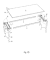
- the folding table is essentially composed of a base and resting on the table top 3 .
- the underframe consists of two spaced-apart legs 2 and in a horizontal plane between them inserted frame rods 6.
- the table top 3 has a top 31 as a work surface and has a bottom 32 .
- the single leg 2 is composed of two mutually spaced supports 20, each having a lower end 22 and an upper end 21 , and a connected to the upper ends 21 cross member 23 together.
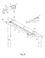
- a stationary first axis of rotation A1 which is connected to a next, movable, second axis of rotation A2 (see FIG. 2A), on which the mechanism 1 is articulated, extends through the transverse member 23 .
- a spring 18 is arranged, preferably in the form of a leaf spring, while a tension element 19 is located on the underside. This tension element 19 is intended for gripping by the user.
- Another movable third axis of rotation A3 extends through the mechanism 1 (see Figure 2A). The third axis of rotation A3 is followed in principle by a stationary fourth axis of rotation A4, to which the mechanism 1 is articulated on the other hand.
- the legs 2 are preferably of tubular section of circular cross-section, while for the frame bars 6, tubes of rectangular cross-section are used. All axes of rotation A1, A2, A3, A4 are parallel to each other.
- the supports 20 of the legs 2 extend away from the tabletop lower side 32 and the lower leg ends 22 are intended for placement on the floor (see Figures 1A to 1D).
- the supports 20 of the legs 2 come to lie close to or directly on the tabletop underside 32 and the lower leg ends 22 are directed towards each other (see Figure 1 E).
- a lower bearing part 4 is attached to the cross member 23 , to which an upper bearing part 5 is added.
- Both bearing parts 4,5 each have a cavity 40,50, so that in the assembled state, the cross section of the transverse member 23 rotatable in the mutually facing Excavations 40,50 is located.
- the bearing parts 4.5 are connected to each other, for example by screwing.
- the respective inner side of each combination of the bearing parts 4, 5 is assigned an eccentric disk 24 which sits firmly on the transverse member 23 , through which the first axis of rotation A1 extends.
- the second axis of rotation A2 which is formed by the second axle rod 14 which is inserted in the tube portion 120 of the second lever 12 extends.
- a web 122 sets, which opens into a bar segment 123 .
- the web 122 Underneath the web 122 is an arc segment 121 which extends approximately over a quarter circle and leaves a gap between the web 121 and the rod segment 123 .
- the second lever 12 is thus rotatably articulated on the second axis of rotation A2 , which in turn is pivotally connected to the first lever 11 on the third axis of rotation A3, which is formed by the rod segment 123 .
- the rod segment 123 is inserted in a circular third channel section 114 of the first lever 11. In order to enable the rotational movement of the rod segment 123 with the opening web 122 in the third channel section 114 , this is open via an axially extending longitudinal slot whose opening angle is smaller than 180 ° so that the bar segment 123 is encompassed so far that the latter can not slide laterally out of the slot.
- the first lever 11 is connected to the second lever 12 by inserting the rod segment 123 axially into the channel portion 114 .
- Adjoining the channel section 114 is a plate section 112 , which opens into a tube section 110 , on which a first channel section 111 extends axially. This channel section 111 also has an open longitudinal slot facing upwards.
- Adjacent to the third channel portion 114 is located on the underside of the plate portion 112, a second channel portion 113 with a downwardly open longitudinal slot.
- the first axle rod 13 which forms the fourth axis of rotation A4 .
- the first lever 11 is articulated to the pipe section 110 on the first axle rod 13 .
- the spring 18 is fixed, on the other hand engages the tubular portion 120 of the second lever 12 .
- a plurality of such springs 18 may be used symmetrically.
- the spring 18 developed a force to push apart the two connected to each other on the third axis of rotation A3 lever 11,12 . In the maximum apart moved position of the levers 11,12 come the second, third and fourth axis A2, A3, A4 lie on one level, are quasi on a line in a dead center position.
- the two ends of the first axle rod 13 protrude from the pipe section 110 and have mutually parallel flats 130.
- Each of the ends of the first axle rod 13 is fixed in a slot 54 of the associated upper bearing part 5 .
- the adjusted positioning of the first axle rod 13 in the oblong holes 54 is adjusted by means of an adjusting element 55 , for example, as a seated in the upper bearing parts 5 screw projects into the respective slot 54 and pushes the end of the first axle rod 13 stuck therein.
- the upper sides of the upper bearing parts 5 form bearing surfaces 52 for mounting the underside of the tabletop 32.
- Each upper bearing part 5 has an inner shoulder 51, against which a stop 25 in the position of use of the legs 2 bounces.
- the stop 25 is disposed on the cross member 23 or on the eccentric discs 24 and is thus moved during the pivoting of the legs 2 .
- an upwardly open further channel section could be provided on the tube section 120 .
- the lever combination 11,12 In the position of use with the legs 2 facing the ground, the lever combination 11,12 is inclined from the second axis of rotation A2 ascending to the fourth axis of rotation A4 and is in the locked state, so that an unintentional collapse of a leg 2, for example by bumping a user, is prevented (see Figures 2A to 2C).
- the lever combination 11,12 from the second axis of rotation A2 to the fourth axis of rotation A4 in principle is horizontally and is also in the locked state, so that unintentional unfolding of a leg 2, for example Lifting the table is prevented (see Figure 2D).
- the eccentric discs 24 With the pivoting of the legs 2 about the stationary first axis of rotation A1 in the folded position, the eccentric discs 24 have rotated, so that the second portable The axis of rotation A2 has moved upwards about the first axis of rotation A1 , and the third axis of rotation A3 has also been pulled upwards and the first lever 11 has rotated about the fourth axis of rotation A4 .
- a corner receptacle 53 which serves to insert the adjacent end of the frame bar 6 .
- the end of the frame bar 6, as well as the table top 3, are bolted to the upper bearing part 5 . It can be provided between the table top 3 and the frame bars 6 further screwing.
Landscapes
- Tables And Desks Characterized By Structural Shape (AREA)
Applications Claiming Priority (1)
| Application Number | Priority Date | Filing Date | Title |
|---|---|---|---|
| DE200620011874 DE202006011874U1 (de) | 2006-08-01 | 2006-08-01 | Klapptisch |
Publications (2)
| Publication Number | Publication Date |
|---|---|
| EP1884176A2 true EP1884176A2 (fr) | 2008-02-06 |
| EP1884176A3 EP1884176A3 (fr) | 2009-05-06 |
Family
ID=37311592
Family Applications (1)
| Application Number | Title | Priority Date | Filing Date |
|---|---|---|---|
| EP07405228A Withdrawn EP1884176A3 (fr) | 2006-08-01 | 2007-08-01 | Table pliante |
Country Status (2)
| Country | Link |
|---|---|
| EP (1) | EP1884176A3 (fr) |
| DE (1) | DE202006011874U1 (fr) |
Cited By (1)
| Publication number | Priority date | Publication date | Assignee | Title |
|---|---|---|---|---|
| US20150282605A1 (en) * | 2014-04-03 | 2015-10-08 | Timotion Technology Co., Ltd. | Collapsible power-driven table stand |
Family Cites Families (1)
| Publication number | Priority date | Publication date | Assignee | Title |
|---|---|---|---|---|
| DE102004054934B3 (de) * | 2004-11-13 | 2006-03-02 | Kusch & Co. Sitzmöbelwerke GmbH & Co. KG | Klapptisch |
-
2006
- 2006-08-01 DE DE200620011874 patent/DE202006011874U1/de not_active Expired - Lifetime
-
2007
- 2007-08-01 EP EP07405228A patent/EP1884176A3/fr not_active Withdrawn
Cited By (4)
| Publication number | Priority date | Publication date | Assignee | Title |
|---|---|---|---|---|
| US20150282605A1 (en) * | 2014-04-03 | 2015-10-08 | Timotion Technology Co., Ltd. | Collapsible power-driven table stand |
| US20160037904A1 (en) * | 2014-04-03 | 2016-02-11 | Timotion Technology Co., Ltd. | Collapsible power-driven table stand |
| US9271567B2 (en) * | 2014-04-03 | 2016-03-01 | Timotion Technology Co., Ltd. | Collapsible power-driven table stand |
| US9427080B2 (en) * | 2014-04-03 | 2016-08-30 | Timotion Technology Co., Ltd. | Collapsible power-driven table stand |
Also Published As
| Publication number | Publication date |
|---|---|
| EP1884176A3 (fr) | 2009-05-06 |
| DE202006011874U1 (de) | 2006-10-19 |
Similar Documents
| Publication | Publication Date | Title |
|---|---|---|
| EP1971245B1 (fr) | Mecanisme a contact permanent | |
| EP2796121B1 (fr) | Fauteuil roulant pliable | |
| EP2298133A1 (fr) | Chaise | |
| DE19902467B4 (de) | Sessel mit Aufstehhilfe | |
| DE202018002383U1 (de) | Klapptisch | |
| EP0663164B1 (fr) | Meuble muni d'un plateau fixe et d'au moins deux plateaux supplémentaires | |
| EP2369965A2 (fr) | Bras central destiné à maintenir une plaque supérieure de gril double ou une plaque supérieure de cuisson et gril double ou appareil de cuisson équipé de ce bras central | |
| DE3613005A1 (de) | Metalltisch | |
| EP3528664B1 (fr) | Dispositif de mécanisme synchrone et chaise en étant équipée | |
| DE202004012593U1 (de) | Vorrichtung zur Festlegung und/oder Positionierung von Gegenständen in einem Transportbehälter | |
| DE102005025813B4 (de) | Stapelsäule zum Stapeln und Transportieren von Teilen, wie von Karosserieblechen oder dergleichen | |
| EP2083656B1 (fr) | Accoudoir réglable en hauteur, notamment pour une chaise de bureau | |
| WO2008028306A2 (fr) | Table réglable en hauteur | |
| CH716838A1 (de) | Traverse, Traversensatz und Möbelbausatz. | |
| DE102015008908A1 (de) | Verriegelungssystem, insbesondere für Bierzeltgarnitur | |
| EP1884176A2 (fr) | Table pliante | |
| EP3369345A1 (fr) | Surface de couchage pourvue de dispositif de réglage de l'inclinaison | |
| EP1958885B1 (fr) | Récipient pliant | |
| EP2286690B1 (fr) | Table variable | |
| DE10038223B4 (de) | Klapptisch | |
| EP3437520B1 (fr) | Mécanisme basculant | |
| DE202020106859U1 (de) | Klappscharnier für zwischen einer Verstaustellung und einer Gebrauchsstellung schwenkbare Platten | |
| DE102006048279B4 (de) | Tisch | |
| EP2081466B1 (fr) | Table pliante | |
| DE2642739A1 (de) | Neigungsvorrichtung fuer sitzmoebel |
Legal Events
| Date | Code | Title | Description |
|---|---|---|---|
| PUAI | Public reference made under article 153(3) epc to a published international application that has entered the european phase |
Free format text: ORIGINAL CODE: 0009012 |
|
| AK | Designated contracting states |
Kind code of ref document: A2 Designated state(s): AT BE BG CH CY CZ DE DK EE ES FI FR GB GR HU IE IS IT LI LT LU LV MC MT NL PL PT RO SE SI SK TR |
|
| AX | Request for extension of the european patent |
Extension state: AL BA HR MK YU |
|
| PUAL | Search report despatched |
Free format text: ORIGINAL CODE: 0009013 |
|
| AK | Designated contracting states |
Kind code of ref document: A3 Designated state(s): AT BE BG CH CY CZ DE DK EE ES FI FR GB GR HU IE IS IT LI LT LU LV MC MT NL PL PT RO SE SI SK TR |
|
| AX | Request for extension of the european patent |
Extension state: AL BA HR MK RS |
|
| AKX | Designation fees paid | ||
| REG | Reference to a national code |
Ref country code: DE Ref legal event code: 8566 |
|
| STAA | Information on the status of an ep patent application or granted ep patent |
Free format text: STATUS: THE APPLICATION IS DEEMED TO BE WITHDRAWN |
|
| 18D | Application deemed to be withdrawn |
Effective date: 20091107 |