EP1884331A1 - Unité de coupe interne de rasoir rotatif et rasoir rotatif doté de celle-ci - Google Patents
Unité de coupe interne de rasoir rotatif et rasoir rotatif doté de celle-ci Download PDFInfo
- Publication number
- EP1884331A1 EP1884331A1 EP07253088A EP07253088A EP1884331A1 EP 1884331 A1 EP1884331 A1 EP 1884331A1 EP 07253088 A EP07253088 A EP 07253088A EP 07253088 A EP07253088 A EP 07253088A EP 1884331 A1 EP1884331 A1 EP 1884331A1
- Authority
- EP
- European Patent Office
- Prior art keywords
- cutter
- inner cutter
- blade
- blade supports
- rotary shaver
- Prior art date
- Legal status (The legal status is an assumption and is not a legal conclusion. Google has not performed a legal analysis and makes no representation as to the accuracy of the status listed.)
- Granted
Links
- 239000000463 material Substances 0.000 description 14
- 238000010586 diagram Methods 0.000 description 12
- 230000002159 abnormal effect Effects 0.000 description 7
- 230000001186 cumulative effect Effects 0.000 description 6
- 238000005520 cutting process Methods 0.000 description 4
- 230000000694 effects Effects 0.000 description 3
- 238000004519 manufacturing process Methods 0.000 description 3
- 238000003754 machining Methods 0.000 description 2
- 238000005406 washing Methods 0.000 description 2
- XLYOFNOQVPJJNP-UHFFFAOYSA-N water Substances O XLYOFNOQVPJJNP-UHFFFAOYSA-N 0.000 description 2
- 208000003028 Stuttering Diseases 0.000 description 1
- XSTXAVWGXDQKEL-UHFFFAOYSA-N Trichloroethylene Chemical group ClC=C(Cl)Cl XSTXAVWGXDQKEL-UHFFFAOYSA-N 0.000 description 1
- 230000002411 adverse Effects 0.000 description 1
- 230000009286 beneficial effect Effects 0.000 description 1
- 230000003749 cleanliness Effects 0.000 description 1
- 239000002184 metal Substances 0.000 description 1
- 229910052751 metal Inorganic materials 0.000 description 1
- 239000007769 metal material Substances 0.000 description 1
- 150000002739 metals Chemical class 0.000 description 1
- 238000000034 method Methods 0.000 description 1
- 238000012986 modification Methods 0.000 description 1
- 230000004048 modification Effects 0.000 description 1
- 239000004033 plastic Substances 0.000 description 1
- 229920003023 plastic Polymers 0.000 description 1
- 238000003825 pressing Methods 0.000 description 1
- 229910001220 stainless steel Inorganic materials 0.000 description 1
- 239000010935 stainless steel Substances 0.000 description 1
- 230000002459 sustained effect Effects 0.000 description 1
- UBOXGVDOUJQMTN-UHFFFAOYSA-N trichloroethylene Natural products ClCC(Cl)Cl UBOXGVDOUJQMTN-UHFFFAOYSA-N 0.000 description 1
- 238000004506 ultrasonic cleaning Methods 0.000 description 1
- 238000012795 verification Methods 0.000 description 1
- 239000002023 wood Substances 0.000 description 1
Images




Classifications
-
- B—PERFORMING OPERATIONS; TRANSPORTING
- B26—HAND CUTTING TOOLS; CUTTING; SEVERING
- B26B—HAND-HELD CUTTING TOOLS NOT OTHERWISE PROVIDED FOR
- B26B19/00—Clippers or shavers operating with a plurality of cutting edges, e.g. hair clippers, dry shavers
- B26B19/14—Clippers or shavers operating with a plurality of cutting edges, e.g. hair clippers, dry shavers of the rotary-cutter type; Cutting heads therefor; Cutters therefor
- B26B19/141—Details of inner cutters having their axes of rotation perpendicular to the cutting surface
Definitions
- the present invention relates to an inner cutter for a rotary shaver and to a rotary shaver that uses the same and more particularly to an inner cutter for a rotary shaver in which the material thereof can be made thin and which exhibits outstanding anti-wear properties and to a rotary shaver using such an inner cutter.
- cutter blades of inner cutter are usually inclined in the direction in which the inner cutter rotates as shown in, for instance, Fig. 6 of Japanese Patent Application Laid-Open (Kokai) No. 2005-185827 .
- the reason for the inclined cutter blades is that, by taking the shape like that of Fig. 6 in Japanese Patent Application Laid-Open (Kokai) No. 2005-185827 , it becomes possible to effect good shaves even with a thin-material structure.
- the structure in which the cutter blades of the inner cutter in a rotary shaver are inclined in the direction of rotation of the inner cutter means that the position of the leading tip end portions (or leading edge portions) of the cutter blades of the inner cutter are located forward, relative to the base portions thereof, in the direction of rotation of the inner cutter.
- an inner cutter guide vibration-preventing member which is for supporting the lower surface of the inner cutter main body is provided in an inner cutter guide that connects the inner cutter to the output shaft of a drive means provided in the rotary shaver, so that the lower surface of the inner cutter main body is supported thereby, and thus preventing vibration when the inner cutter is rotated.
- Fig. 15 shows illustrations that represent a blackboard and a piece of chalk when a line is being drawn on the blackboard with the chalk.
- An object of the present invention is to provide an inner cutter for a rotary shaver and a rotary shaver that uses the same, wherein, by preventing the chalk phenomenon caused between the inner cutter and outer cutter, the deployment of parts which is for suppressing (minute) vibrations in the inner cutter is made unnecessary, abnormal wear in the inner and outer cutters is prevented by maintaining the sliding condition between the inner cutter and the outer cutter in a suitable condition, and cutting sharpness is well maintained for a long time even with a thin-material structure in the inner cutter.
- the inner cutter is comprised of a plurality of blade supports formed so as to be raised from an inner cutter main body, and cutter blades provided, respectively, at the tip ends of the blade supports, and in this inner cutter, the positions where the blade supports are raised are located more forward in the direction of rotation of the inner cutter than the positions of the leading blade-tip of the cutter blades.
- At least one bent portion or curved portion is formed in each one of the blade supports.
- cutter blades are provided at the tip ends of the blade supports without changing the linear form (or the curvature) in the tip ends of the blade supports.
- the blade supports are inclined backward in the direction of the rotation of the inner cutter.
- the height position of the cutter blades, when the inner cutter is rotated, can be lower than the height position of the cutter blades prior to rotating the inner cutter; and a result, it is possible to prevent the occurrence of the chalk phenomenon that would occur by the cutter blades and the outer cutter. Accordingly, in the inner cutter of the present invention, the condition in which the cutter blades and the outer cutter slide against each other is maintained in a suitable condition, and, abnormal wear in the cutter blades and outer cutter can be prevented.
- a unique structure of the present invention for a rotary shaver that includes a shaver frame body, a power supply unit and an inner cutter drive unit both provided in the shaver frame body, an inner cutter(s) that is(are) rotationally driven in linkage with the inner cutter drive unit, and an outer cutter(s) for shaving hair in cooperation with the (rotating) inner cutter(s), and in this shaver, the inner cutter(s) is(are) comprised of a plurality of blade supports formed so as to be raised from an inner cutter main body(s), and cutter blades provided, respectively, at the tip ends of the blade supports; and in this structure, the positions where the blade supports are raised are located more forward in the direction of rotation of the inner cutter(s) than the positions of the leading blade-tip of the cutter blades.
- At least one bent portion or curved portion is formed in each one of the blade supports of the inner cutter(s).
- the cutter blades are provided at the tip ends of the blade supports without changing the linear form (or the curvature) in the tip ends of the blade supports.
- the blade supports are inclined backward in the direction of the rotation of the inner cutter(s).
- the blade supports exhibit deflection oriented backward in the direction of the rotation of the inner cutter when the cutter blades are subjected to a sliding resistance with the outer cutter, or when a load is sustained during shaving. Due to such deflection, the cutter blades of the inner cutter will pull away from the blade surfaces of the outer cutter, so that the chalk phenomenon is avoided, and abnormal wear in the cutter blades and outer cutter is prevented.
- the hair cutting sharpness of the rotary shaver is maintained for a long period of time even when the shaver that uses the inner cutter(s) is used in the unoiled condition after washing.
- Fig. 1 shows a rotary shaver according to the embodiments of the present invention.
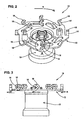
- Fig. 2 is a perspective view of the inner cutter for a rotary shaver of one embodiment.
- Fig. 3 is a front view thereof.
- Fig. 4 is an enlarged explanatory diagram of Portion A in Fig. 2.
- the rotary shaver 100 is an electrically chargeable type shaver that includes a chargeable battery which is a power supply (power source) and a motor which is a drive unit housed inside the frame body 40 of the shaver (and thus neither the chargeable battery or the motor are shown in Fig. 1).
- a chargeable battery which is a power supply (power source)
- a motor which is a drive unit housed inside the frame body 40 of the shaver (and thus neither the chargeable battery or the motor are shown in Fig. 1).
- three inner cutters 10 see Figs. 2 to 4
- three outer cutters 30, which are for cutting hair in conjunction with the inner cutters 10 are provided such that they, respectively, are detachable with respect to the shaver frame body 40.
- three pairs of outer and inner cutters are provided in the shaver 100 (or in the shaver frame body 40) so as to be arranged in a triangular shape; and the present invention is applicable to rotary shavers with different number(s) of outer and inner cutters than the shown embodiment.
- the inner cutter 10 for the rotary shaver 10 (hereinafter sometimes referred to simply as the "inner cutter 10") shown in Figs 2 to 4 is formed of thin stainless steel sheet.
- the inner cutter 10 is comprised of an inner cutter main body 12 having underneath an inner cutter guide 13 which is connected to the output shaft of the drive unit housed in the shaver frame body of the rotary shaver 100, a plurality of blade supports 14 raised from the inner cutter main body 12, and a cutter blade 16 formed at the tip end portion (or the upper end portion in the drawings) of each one of the blade supports 14.
- the cutter blades 16 in this embodiment are provided in two rows, on the inner circumference side and on the outer circumferential side, in the radial direction of the inner cutter main body 12.
- the cutter blades 16 slide, with a prescribed frictional force, against inner surface of the outer cutter 30, in inner circumferential side slits 32a and outer circumferential side slit 32b in each one of the outer cutters 30, which are shown in Fig. 1.
- Hair entered through the slits 32a and 32b into the interior of the outer cutter 30 is cut by the cutter blades 16 (of the rotating inner cutter 10) that slide over the inner surfaces of the portions between the slits 32a and 32b.
- the blade supports 14 are formed at equal intervals in the direction of rotation of the inner cutter 10 in the inner cutter main body 12.
- the blade supports 14 are formed by being cut from the inner cutter main body 12.
- the blade supports 14, after being cut from the inner cutter main body 12, are bent and raised on the inner cutter main body 12 so as to be inclined in a direction opposite from the direction of rotation of the inner cutter 10 (the rotational direction of the inner cutter 10 is shown by arrow R in Fig. 4).
- the cutter blades 16 are formed, as described above, at the tip end portions 14b of the blade supports 14.
- the cutter blades 16 are formed so as to be inclined in a direction opposite from the direction of inclination of the blade supports 14.
- the cutter blades 16 are formed so that they are, from the points of the tip end portions 14b of the blade supports 14, inclined forward in the direction of rotation of the inner cutter 10 shown by arrows R in Fig. 3. More specifically, the blade supports 14 are raised so as to incline in the direction opposite from the rotational direction R of the inner cutter 10, and the cutter blades 16 are formed on the blade supports so as to be inclined into the rotational direction R of the inner cutter 10.
- the blade supports 14 and the cutter blades 16 are formed so as to take a substantially inverted L shape (or in a ">" shape as seen from drawings). Causing the cutter blades 16 to be inclined in the direction of rotation of the inner cutter 10 in this manner allows the feel of the shave to be enhanced, even with a thin-material structure (or even if the inner cutter main body 12, the blade supports 14, and the cutter blades 16 are made of a thin metal material of, for instance, 0.3 mm), and thus it is advantageous.
- the blade supports 14 and the cutter blades 16 in the shown embodiment are formed integrally, and they can be formed by press machining.
- the position X of each one of the raised portions 14a of each one of the blade supports 14 that is the portion of the blade support 14 raised up from the inner cutter main body 12 is set to be located forward in the direction of rotation of the inner cutter 10 relative to the position Y of the reverse bent portion 14c which is substantially inverted L shape formed by the cutter blade 16 and (the tip end portion 14b of) the blade support 14.
- the position X of each one of the raised portions 14a is set to be located forward in the direction of rotation of the inner cutter 10 relative to a position Z where the leading tip end (blade tip end or blade's forward edge) 16a of the cutter blade 16 is located.
- the leading edge 16a of each cutter blade 16 is behind the raised portion 14a of the blade support with reference to the rotational direction R of the inner cutter 10.
- each of the raised portions 14a, support tip end portions 14b, bent portions 14c, and leading tip ends (blade tip end or blade's forward edge) 16a so that their positional relationships are as described above, an action in which the cutter blades 16 pull away from the outer cutter when the inner cutter 10 is rotated occurs; and as a result, abnormal sliding between the cutter blades 16 and the outer cutter is prevented assuredly. Accordingly, anything that would adversely affect the feel of the shave, such as wear in the cutter blades 16 and outer cutter 30 and/or blade breakage is prevented.
- Fig. 5 is a graph representing the results of durability tests on the inner cutter for a rotary shaver in the shown embodiment and inner cutter for rotary shavers of conventional art.
- inner cutters and outer cutters after being cleaned in a trichloroethylene ultrasonic cleaning machine, and after verification that they had been degreased, were connected to the output shaft (rotating shaft) of rotary shavers having a common configuration.
- the inner cutters on rotary shavers are rotated for three minutes and then the rotation is stopped for three minutes, and this action was performed repeatedly. These on-off actions were repeated until the cumulative on time of the on-off actions reached 100 hours.
- the cutter blades 16 are formed at the tip ends of blade supports 14 that are, as shown in Figs. 6A and 6B, raised from the inner cutter main body 12 so that the tip end portions of the blade supports 14 are inclined forward in the rotational direction R of the inner cutters.
- the blade supports 14 and the cutter blades 16 are, as seen from Figs. 6A and 6B, formed in a straight line.
- the sheet thicknesses of the blade supports 14 in samples A and B are, respectively, 0.5 mm and 0.3 mm.
- Sample A was given an NG judgment, with an average value of cumulative time being 20.2 hours.
- Sample B was also given an NG judgment, with an average value of cumulative time being 6.3 hours.
- the cutter blades 16 are, as shown in Figs. 7A and 7B, formed at the tip ends of blade supports 14 raised from the inner cutter main body 12 so that the tip end portions are inclined forward in the rotational direction R of the inner cutters.
- the blade supports 14 and the cutter blades 16 are formed in a straight line.
- the sheet thicknesses of the blade supports 14 in samples C and D are, respectively, 0.5 mm and 0.3 mm.
- inner cutter guide swing-prevention members 20 are provided for supporting the lower surface of the inner cutter main body 12.
- Sample C was given an OK judgment.
- Sample D was given an NG judgment, with an average value of cumulative time being 5.8 hours.
- sample A and sample C and, likewise, between sample B and sample D, are, in both cases, the difference of providing or not providing the inner cutter guide swing-preventing members 20. Looking at the results of the durability tests for sample A and sample C, it can be seen that providing the inner cutter guide swing-preventing members 20 is beneficial; however, looking at the results of the durability tests for sample B and sample D, there is no benefit in providing the inner cutter guide swing-preventing members 20.
- the inner cutters 10 in samples E and F in Fig. 5 have the same shape as shown in Fig. 2 to 4 and described for the embodiment above. As seen from Fig. 5, the results of the durability tests were that OK judgments were given to both samples E and F.
- inner cutters have satisfactory durability, even when the sheet thickness of the blade supports 14 (that is, of the inner cutter main body 12 and cutter blades 16) is given a thin-material structure (having a 0.3 mm thickness).
- the chalk phenomenon between the cutter blade 16 and the outer cutter is prevented, so that the quality of the inner cutter 10 is enhanced at low cost.
- the inner cutter for a rotary shaver according to the present invention is not limited to or by the embodiment described above; and, needless to say, such inner cutters as those in which various modifications are made within the scope not altering the characteristics of the invention are within the technical scope of the present invention.
- the inner cutter 10 (or the blade support 14 and cutter blade) is in an inverted L (or ">") shape as shown in, for instance, Fig. 2, but the inner cutter 10 of the present invention is not limited to or by this shape.
- the inner cutter 10 can be formed so that, as shown in Fig. 8, the blade support 14 is raised or erected perpendicular to the inner cutter main body 12 and bent in the direction opposite from the inner cutter rotating direction R, and then the blade tip end of the cutter blade 16 at the tip end portion 14b of the blade support 14 is oriented in the direction of rotation of the inner cutter 10.
- the blade support 14 is raised from the inner cutter main body 12 and inclined backward in the rotational direction R of the inner cutter 10 (or inclined in the opposite direction to the rotational direction R of the inner cutter 10), and then the thickness of the material midway along the blade support 14 is made smaller by press machining or the like so as effect a mode in which the elasticity is adjusted.
- the blade tip of the cutter blade 16 at the tip end portion 14b of the blade support 14 is of course provided so that it is oriented in the direction of rotation of the inner cutter 10.
- the (size of the) angle ⁇ between the blade support 14 and the cutter blade 16 and the (size of the) angle ⁇ between the blade support 14 and the inner cutter main body 12 are not particularly limited, and such angles can be freely set insofar as it lies within the range that satisfies the present invention.
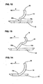
- Fig. 10 and Fig. 11 it is also possible, as shown in Fig. 10 and Fig. 11, to provide bent portions 14c at a plurality of locations in each one of the blade supports 14 that are raised from the inner cutter main body 12 and inclined backward in the direction of rotation of the inner cutter (or in the direction opposite from the rotational direction R of the inner cutter).
- the strength and elasticity of the blade supports 14 is adjusted to a desired condition.
- the cutter blade 16 of the inner cutter can be formed in a circular arc shape at the tip end portion of the blade support 14 that is raised from the inner cutter main body 12.
- This is a mode in which the bent portion 14c is formed midway along the blade support 14 which is raised from the inner cutter main body 12, and then the portion between the bent portion 14c and the cutter blade 16 is formed in a circular arc to form a curved shape.
- the tip end (blade tip portion) of the cutter blade 16 is oriented in the rotational direction R of the inner cutter 10.
- the blade support 14 raised from the inner cutter main body 12 needs only to be such that the blade support 14 is not inclined forward in the direction of rotation of the inner cutter 10 (or in the same direction as the inner cutter rotational direction R), and, needless to say, it is also possible to erect the blade support 14 perpendicularly from the inner cutter main body 12 and the curved blade support 14 is formed thereon as shown in Fig. 12.
- the entire shape of the blade support 14 is formed in a circular arc, and the cutter blade 16 is provided so as to coincide with the linearity or the curvature of the entire shape of the blade support 14, so that the blade support 14 and the cutter blade 16 assume the same circular arc or curved shape.
- the position of the raised portion 14a of the blade support 14 is set at a position which is more forward in the rotational direction R of the inner cutter 10 than the position of the leading edge (blade tip end or blade's forward edge) of the cutter blade 16.
- the blade supports 14 are raised (or erected) in a plurality of rows in the radial direction in the inner cutter main body 12; however, it is not absolutely necessary that the number of raised portions (blades supports) on the outer circumferential side coincide with the number of raised portions (blades supports) on the inner circumferential side, and thus the number of raised portions on the inner circumferential side and the outer circumferential side can be different.
Landscapes
- Life Sciences & Earth Sciences (AREA)
- Forests & Forestry (AREA)
- Engineering & Computer Science (AREA)
- Mechanical Engineering (AREA)
- Dry Shavers And Clippers (AREA)
- Toys (AREA)
Applications Claiming Priority (1)
| Application Number | Priority Date | Filing Date | Title |
|---|---|---|---|
| JP2006213877A JP5006595B2 (ja) | 2006-08-04 | 2006-08-04 | ロータリーシェーバー用内刃およびこれを用いたロータリーシェーバー |
Publications (2)
| Publication Number | Publication Date |
|---|---|
| EP1884331A1 true EP1884331A1 (fr) | 2008-02-06 |
| EP1884331B1 EP1884331B1 (fr) | 2010-12-01 |
Family
ID=38626952
Family Applications (1)
| Application Number | Title | Priority Date | Filing Date |
|---|---|---|---|
| EP07253088A Ceased EP1884331B1 (fr) | 2006-08-04 | 2007-08-06 | Unité de coupe interne de rasoir rotatif et rasoir rotatif doté de celle-ci |
Country Status (5)
| Country | Link |
|---|---|
| US (1) | US8434233B2 (fr) |
| EP (1) | EP1884331B1 (fr) |
| JP (1) | JP5006595B2 (fr) |
| CN (1) | CN101116975B (fr) |
| DE (1) | DE602007010870D1 (fr) |
Cited By (4)
| Publication number | Priority date | Publication date | Assignee | Title |
|---|---|---|---|---|
| WO2009129695A1 (fr) * | 2008-04-25 | 2009-10-29 | Tang Huiping | Ensemble de rasage à bagues multiples |
| US20120011724A1 (en) * | 2009-03-30 | 2012-01-19 | Koninklijke Philips Electronics N.V. | Carrier for a shaving device, comprising pairs of a cutting element and a hair lifting element |
| EP2602071A1 (fr) * | 2011-12-09 | 2013-06-12 | Rovcal, Inc. | Couteau interne pour rasoir rotatif |
| US11272772B2 (en) | 2016-05-16 | 2022-03-15 | Spectrum Brands, Inc. | Heated hair setter apparatus and method |
Families Citing this family (13)
| Publication number | Priority date | Publication date | Assignee | Title |
|---|---|---|---|---|
| US9027251B2 (en) | 2009-04-29 | 2015-05-12 | Spectrum Brands, Inc. | Rotary electric shaver |
| EP2602072A3 (fr) * | 2011-12-09 | 2013-08-14 | Rovcal, Inc. | Couteau interne pour rasoir rotatif |
| EP2802437B1 (fr) * | 2012-01-10 | 2016-11-02 | Koninklijke Philips N.V. | Appareil de rasage rotatif |
| CN103692458A (zh) * | 2013-12-30 | 2014-04-02 | 超人集团有限公司 | 剃须刀的内刀 |
| JP6339417B2 (ja) * | 2014-05-30 | 2018-06-06 | 株式会社泉精器製作所 | ロータリー式電気かみそり |
| JP2016067589A (ja) * | 2014-09-30 | 2016-05-09 | 株式会社泉精器製作所 | ロータリー式電気かみそり |
| WO2016135845A1 (fr) * | 2015-02-24 | 2016-09-01 | 株式会社泉精器製作所 | Lame interne pour rasoir électrique rotatif |
| JP6478772B2 (ja) * | 2015-04-03 | 2019-03-06 | マクセルホールディングス株式会社 | 電気かみそり |
| JP6688049B2 (ja) * | 2015-11-24 | 2020-04-28 | マクセルイズミ株式会社 | ロータリー式電気かみそりおよびロータリー式電気かみそりの内刃の製造方法 |
| JP6383842B2 (ja) * | 2017-07-21 | 2018-08-29 | 株式会社泉精器製作所 | ロータリー式電気かみそりの内刃 |
| EP3659759A1 (fr) | 2018-11-28 | 2020-06-03 | Koninklijke Philips N.V. | Unité de coupe de cheveux dotée d'une prévention du blocage de la lame |
| CN110103263A (zh) * | 2019-05-31 | 2019-08-09 | 宁波美钻机电有限公司 | 一种旋转式电动修眉刀片 |
| CN114368011B (zh) * | 2022-02-09 | 2024-12-20 | 浙江海顺电工有限公司 | 剃毛刀动刀 |
Citations (6)
| Publication number | Priority date | Publication date | Assignee | Title |
|---|---|---|---|---|
| DE1225991B (de) * | 1965-02-17 | 1966-09-29 | Otto Huebner | Rotierender Messerkopf fuer Siebscherkoepfe von Trockenrasiergeraeten |
| US3710442A (en) * | 1969-12-05 | 1973-01-16 | G Meyer | Dry shaving apparatus |
| US4227301A (en) | 1977-11-28 | 1980-10-14 | U.S. Philips Corporation | Shaving apparatus |
| EP0094128A1 (fr) * | 1982-05-06 | 1983-11-16 | Koninklijke Philips Electronics N.V. | Dispositif de rasage |
| EP1175972A2 (fr) * | 2000-07-25 | 2002-01-30 | Izumi Products Company | Couteau intérieur pour rasoir électrique rotatif et rasoir électrique rotatif |
| WO2004012914A1 (fr) * | 2002-07-29 | 2004-02-12 | Koninklijke Philips Electronics N.V. | Appareil de rasage |
Family Cites Families (20)
| Publication number | Priority date | Publication date | Assignee | Title |
|---|---|---|---|---|
| US2824367A (en) * | 1955-06-22 | 1958-02-25 | Arthur C Mcwilliams | Dry shaver having combination suction and adjustable cutting means |
| NL101486C (fr) * | 1959-05-19 | |||
| US4192065A (en) * | 1976-05-14 | 1980-03-11 | U.S. Philips Corporation | Shaving apparatus |
| NL7713046A (nl) * | 1977-11-28 | 1979-05-30 | Philips Nv | Scheerapparaat. |
| NL7713049A (nl) * | 1977-11-28 | 1979-05-30 | Philips Nv | Scheerapparaat. |
| NL7811228A (nl) * | 1978-11-14 | 1980-05-19 | Philips Nv | Scheerapparaat. |
| FI84444C (fi) * | 1985-03-29 | 1991-12-10 | Izumi Seimitsu Kogyo Kk | Framstaellningsmetod foer ett roterande skaerhuvud foer en elektrisk rakapparat. |
| NL8600878A (nl) * | 1986-04-08 | 1987-11-02 | Philips Nv | Scheerapparaat. |
| USD355276S (en) * | 1991-12-28 | 1995-02-07 | Izumi Products Company | Cutter for electric shaver |
| JP3431182B2 (ja) * | 1992-04-17 | 2003-07-28 | 株式会社泉精器製作所 | 電気かみそり |
| JP3521089B2 (ja) * | 1993-02-12 | 2004-04-19 | 株式会社泉精器製作所 | 電気かみそり |
| USD365420S (en) * | 1993-05-28 | 1995-12-19 | Izumi Products Company | Cutter for an electric shaver |
| CN1176789C (zh) * | 2000-05-23 | 2004-11-24 | 皇家菲利浦电子有限公司 | 拉发元件的制造方法、剪切单元和剃须刀装置 |
| DE10228103A1 (de) | 2002-06-24 | 2004-01-15 | Bayer Cropscience Ag | Fungizide Wirkstoffkombinationen |
| JP2005185827A (ja) * | 2003-12-03 | 2005-07-14 | Izumi Products Co | ロータリー式電気かみそり |
| WO2006000937A1 (fr) * | 2004-06-21 | 2006-01-05 | Koninklijke Philips Electronics N.V. | Rasoir |
| JP5021484B2 (ja) * | 2004-11-01 | 2012-09-05 | コーニンクレッカ フィリップス エレクトロニクス エヌ ヴィ | 異なる半径にカッタブレードを備えるインナカッタ、かかるユニットの製造方法、シェーバヘッド及びそれを備える回転シェーバ |
| JP2007135991A (ja) * | 2005-11-21 | 2007-06-07 | Izumi Products Co | ロータリー式電気かみそり |
| EP2086728B1 (fr) * | 2006-11-15 | 2017-04-26 | Koninklijke Philips N.V. | Procédé de fabrication d'un élément de coupe d'un rasoir |
| JP2008154736A (ja) * | 2006-12-22 | 2008-07-10 | Izumi Products Co | ロータリー式電気かみそりおよび内刃 |
-
2006
- 2006-08-04 JP JP2006213877A patent/JP5006595B2/ja not_active Expired - Fee Related
-
2007
- 2007-08-06 US US11/890,423 patent/US8434233B2/en active Active
- 2007-08-06 EP EP07253088A patent/EP1884331B1/fr not_active Ceased
- 2007-08-06 CN CN2007101401362A patent/CN101116975B/zh not_active Expired - Fee Related
- 2007-08-06 DE DE602007010870T patent/DE602007010870D1/de active Active
Patent Citations (6)
| Publication number | Priority date | Publication date | Assignee | Title |
|---|---|---|---|---|
| DE1225991B (de) * | 1965-02-17 | 1966-09-29 | Otto Huebner | Rotierender Messerkopf fuer Siebscherkoepfe von Trockenrasiergeraeten |
| US3710442A (en) * | 1969-12-05 | 1973-01-16 | G Meyer | Dry shaving apparatus |
| US4227301A (en) | 1977-11-28 | 1980-10-14 | U.S. Philips Corporation | Shaving apparatus |
| EP0094128A1 (fr) * | 1982-05-06 | 1983-11-16 | Koninklijke Philips Electronics N.V. | Dispositif de rasage |
| EP1175972A2 (fr) * | 2000-07-25 | 2002-01-30 | Izumi Products Company | Couteau intérieur pour rasoir électrique rotatif et rasoir électrique rotatif |
| WO2004012914A1 (fr) * | 2002-07-29 | 2004-02-12 | Koninklijke Philips Electronics N.V. | Appareil de rasage |
Cited By (5)
| Publication number | Priority date | Publication date | Assignee | Title |
|---|---|---|---|---|
| WO2009129695A1 (fr) * | 2008-04-25 | 2009-10-29 | Tang Huiping | Ensemble de rasage à bagues multiples |
| US20120011724A1 (en) * | 2009-03-30 | 2012-01-19 | Koninklijke Philips Electronics N.V. | Carrier for a shaving device, comprising pairs of a cutting element and a hair lifting element |
| US9993929B2 (en) * | 2009-03-30 | 2018-06-12 | Koninklijke Philips N.V. | Carrier for a shaving device, comprising pairs of a cutting element and a hair lifting element |
| EP2602071A1 (fr) * | 2011-12-09 | 2013-06-12 | Rovcal, Inc. | Couteau interne pour rasoir rotatif |
| US11272772B2 (en) | 2016-05-16 | 2022-03-15 | Spectrum Brands, Inc. | Heated hair setter apparatus and method |
Also Published As
| Publication number | Publication date |
|---|---|
| US8434233B2 (en) | 2013-05-07 |
| US20080028618A1 (en) | 2008-02-07 |
| EP1884331B1 (fr) | 2010-12-01 |
| JP5006595B2 (ja) | 2012-08-22 |
| CN101116975B (zh) | 2011-08-31 |
| DE602007010870D1 (de) | 2011-01-13 |
| CN101116975A (zh) | 2008-02-06 |
| JP2008036092A (ja) | 2008-02-21 |
Similar Documents
| Publication | Publication Date | Title |
|---|---|---|
| EP1884331B1 (fr) | Unité de coupe interne de rasoir rotatif et rasoir rotatif doté de celle-ci | |
| EP3585574B1 (fr) | Tondeuse à cheveux portative électrique avec protection de lame | |
| US9789618B2 (en) | Razor head having a low shaving angle | |
| JP6444997B2 (ja) | ブレードセット及び毛切断器具 | |
| EP1566248B1 (fr) | Dispositif pour la coupe de papier | |
| US20080172881A1 (en) | Rotary electric shaver and inner cutter therefor | |
| CN1183339A (zh) | 往复型干式剃刀 | |
| CN101010175A (zh) | 剪发设备 | |
| CN109702265B (zh) | 电池极片的分切刀具以及分切装置 | |
| US10906108B2 (en) | Blade accessory with guide | |
| US20130145917A1 (en) | Apparatus for cutting sheet stack | |
| US20120116432A1 (en) | Tissue sectioning blade | |
| CN2492357Y (zh) | 电动剃刀 | |
| JP6579913B2 (ja) | 回転刃、および回転刃を備えている小型電気機器 | |
| CN106394008B (zh) | 一种用于打印机的高效切刀装置及打印机 | |
| JP4066204B2 (ja) | シート材切断装置 | |
| JP2006015470A (ja) | シート材切断装置 | |
| CN101460278A (zh) | 用于进行往复运动的锯片的导向装置 | |
| JP7252007B2 (ja) | 切断体及び食品切断装置 | |
| CN217967116U (zh) | 一种可顶部剪毛的鼻毛刀头及鼻毛修剪器 | |
| EP4617016A1 (fr) | Rasoir électrique | |
| JP4685560B2 (ja) | 回転刃の研磨装置 | |
| US10583574B2 (en) | Integrated shaving mechanism | |
| CN107128084B (zh) | 一种用于打印机的刀片和刀片组合以及打印机 | |
| CN113771102A (zh) | 刀片结构、刀片单元结构、剃须刀头及剃须装置 |
Legal Events
| Date | Code | Title | Description |
|---|---|---|---|
| PUAI | Public reference made under article 153(3) epc to a published international application that has entered the european phase |
Free format text: ORIGINAL CODE: 0009012 |
|
| 17P | Request for examination filed |
Effective date: 20070816 |
|
| AK | Designated contracting states |
Kind code of ref document: A1 Designated state(s): AT BE BG CH CY CZ DE DK EE ES FI FR GB GR HU IE IS IT LI LT LU LV MC MT NL PL PT RO SE SI SK TR |
|
| AX | Request for extension of the european patent |
Extension state: AL BA HR MK YU |
|
| 17Q | First examination report despatched |
Effective date: 20080717 |
|
| AKX | Designation fees paid |
Designated state(s): DE FR GB |
|
| GRAP | Despatch of communication of intention to grant a patent |
Free format text: ORIGINAL CODE: EPIDOSNIGR1 |
|
| GRAS | Grant fee paid |
Free format text: ORIGINAL CODE: EPIDOSNIGR3 |
|
| GRAA | (expected) grant |
Free format text: ORIGINAL CODE: 0009210 |
|
| AK | Designated contracting states |
Kind code of ref document: B1 Designated state(s): DE FR GB |
|
| REG | Reference to a national code |
Ref country code: GB Ref legal event code: FG4D |
|
| REF | Corresponds to: |
Ref document number: 602007010870 Country of ref document: DE Date of ref document: 20110113 Kind code of ref document: P |
|
| PLBE | No opposition filed within time limit |
Free format text: ORIGINAL CODE: 0009261 |
|
| STAA | Information on the status of an ep patent application or granted ep patent |
Free format text: STATUS: NO OPPOSITION FILED WITHIN TIME LIMIT |
|
| 26N | No opposition filed |
Effective date: 20110902 |
|
| REG | Reference to a national code |
Ref country code: DE Ref legal event code: R097 Ref document number: 602007010870 Country of ref document: DE Effective date: 20110902 |
|
| REG | Reference to a national code |
Ref country code: FR Ref legal event code: PLFP Year of fee payment: 10 |
|
| REG | Reference to a national code |
Ref country code: FR Ref legal event code: PLFP Year of fee payment: 11 |
|
| REG | Reference to a national code |
Ref country code: FR Ref legal event code: PLFP Year of fee payment: 12 |
|
| PGFP | Annual fee paid to national office [announced via postgrant information from national office to epo] |
Ref country code: FR Payment date: 20210819 Year of fee payment: 15 |
|
| PGFP | Annual fee paid to national office [announced via postgrant information from national office to epo] |
Ref country code: DE Payment date: 20210819 Year of fee payment: 15 Ref country code: GB Payment date: 20210820 Year of fee payment: 15 |
|
| REG | Reference to a national code |
Ref country code: DE Ref legal event code: R119 Ref document number: 602007010870 Country of ref document: DE |
|
| GBPC | Gb: european patent ceased through non-payment of renewal fee |
Effective date: 20220806 |
|
| PG25 | Lapsed in a contracting state [announced via postgrant information from national office to epo] |
Ref country code: FR Free format text: LAPSE BECAUSE OF NON-PAYMENT OF DUE FEES Effective date: 20220831 Ref country code: DE Free format text: LAPSE BECAUSE OF NON-PAYMENT OF DUE FEES Effective date: 20230301 |
|
| PG25 | Lapsed in a contracting state [announced via postgrant information from national office to epo] |
Ref country code: GB Free format text: LAPSE BECAUSE OF NON-PAYMENT OF DUE FEES Effective date: 20220806 |