EP1884385A1 - Seitliche verstärkung für kraftfahrzeugtüren - Google Patents
Seitliche verstärkung für kraftfahrzeugtüren Download PDFInfo
- Publication number
- EP1884385A1 EP1884385A1 EP05752222A EP05752222A EP1884385A1 EP 1884385 A1 EP1884385 A1 EP 1884385A1 EP 05752222 A EP05752222 A EP 05752222A EP 05752222 A EP05752222 A EP 05752222A EP 1884385 A1 EP1884385 A1 EP 1884385A1
- Authority
- EP
- European Patent Office
- Prior art keywords
- side reinforcing
- reinforcing element
- element according
- walls
- partitions
- Prior art date
- Legal status (The legal status is an assumption and is not a legal conclusion. Google has not performed a legal analysis and makes no representation as to the accuracy of the status listed.)
- Granted
Links
Images


Classifications
-
- B—PERFORMING OPERATIONS; TRANSPORTING
- B60—VEHICLES IN GENERAL
- B60J—WINDOWS, WINDSCREENS, NON-FIXED ROOFS, DOORS, OR SIMILAR DEVICES FOR VEHICLES; REMOVABLE EXTERNAL PROTECTIVE COVERINGS SPECIALLY ADAPTED FOR VEHICLES
- B60J5/00—Doors
- B60J5/04—Doors arranged at the vehicle sides
- B60J5/042—Reinforcement elements
- B60J5/0422—Elongated type elements, e.g. beams, cables, belts or wires
- B60J5/0438—Elongated type elements, e.g. beams, cables, belts or wires characterised by the type of elongated elements
- B60J5/0443—Beams
- B60J5/0445—Beams formed of several elements arranged in series
Definitions
- the invention is comprised in the field of reinforcement parts or elements for motor vehicle doors.
- the doors normally include side reinforcing elements which basically comprise metallic bars or cross members with a configuration that allows absorbing lateral impacts.
- These reinforcing elements usually have an elongated configuration with a main portion with a substantially trapezoidal cross-section that is U-shaped, sinusoidal-shaped, etc., and with ends with a suitable configuration for fixing the element to the door structure.
- it is usually an element with two fixing ends and with a central part having one or more longitudinal drawings or ribs extending along most of the entire length of the element.
- the design of this central part has the purpose of allowing the element to absorb a large part of the force of a side impact, for example, in the event of an accident.
- the reinforcing element starts to deform, acquiring a deformation in its central area which grows until reaching the material elastic limit, after which point the element no longer withstands any further stress and starts to act like a hinge.
- the objective is to achieve a design which, together with the features of the material used, allows achieving a controlled deformation and delaying the moment in which the "hinge effect" occurs, so as to prevent the element from deforming up to the point where it penetrates the inside of the vehicle and injures its occupants.
- the reinforcing elements must be able to absorb strong impacts and withstand great deformations (as a result of an impact the central part of a reinforcing element can shift a distance of up to 300 mm or more from its initial position) without collapsing.
- a metallic material commonly used for this type of parts is steel with good elastic properties, for example steels such as those mentioned in EP-A-0869019 .
- the use of this type of steel, or of any steel of a very high elastic limit, allows complying with current side impact protection requirements.
- the forming of these steels involves specific and costly manufacturing processes, which limits the possibilities of designing the reinforcing elements so that they are compatible with the surrounding elements and components, for example, with the general door structure and/or with accessories, such as for example, power window motor supports, window regulator tracks, etc.
- the fact that the reinforcing elements are made of metal may make it necessary to apply covers on said elements and/or on components of the door that are close to or in contact with the reinforcing elements so as to reduce or prevent the contact between the reinforcing elements and the surrounding components from producing unwanted noises, corrosion, etc.
- the invention consists of a side reinforcing element for motor vehicles, comprising a first element and a second element.
- the first element is of a first material, specifically of a metallic material, such as a steel combining good mechanical features with good forming. Microalloyed steels with elastic limits less than 480 MPa and dual phase steels with elastic limits less than 650 Microparticle perfectly adapt to these requirements.
- the second element is of a second material different from the first material, such as a plastic material, for example, a glass fiber reinforced plastic material.
- a plastic material for example, a glass fiber reinforced plastic material.
- a material with a good performance combining resistance with easy processing can be chosen. For example, good results have been seen when using glass fiber reinforced polyamides with 30% to 50% by weight of glass fiber. Good results have also been observed with polyamide-based modified copolymers, providing good mechanical features.
- the first element and the second element can be coupled to one another such that when coupled to one another, the reinforcing element has an outer surface at least a part of which is made of said second material.
- the resistance features of the metal are thus combined with the favorable features that other materials (for example, plastics or at least many plastics) have in terms of the possibility of manufacturing the objects with quite varied configurations, which allows obtaining suitable designs for each case.
- the second element may thus incorporate suitable structures for coupling accessories (for example, a power window motor, part of the tracks of the window regulator system, etc.), while at the same time it may have a surface which at least in part is not metallic, which can be advantageous to reduce the risks of noises or corrosion at the contact points between the side reinforcing element and other parts of the door.
- the second element is useful not only for providing greater "design freedom" to the corresponding part of the outer surface of the reinforcing element, but it also contributes to the resistance thereof, so it may advantageously incorporate a structure with suitable walls and partitions to provide resistance against side impacts, as will be described below.
- the first material can be steel or a steel alloy, such as a steel like the one described in EP-A-0869019 or like the one mentioned above.
- the second material can be plastic or another suitable material, for example one of the materials mentioned above.
- the first element can have a configuration defining a longitudinal housing configured to receive a main part of the second element.
- the first element can have a substantially U-shaped cross section, with two side walls (which can be more or less outwardly divergent) joined by a central part. These walls and central part can form the longitudinal housing.
- the side walls can end in respective longitudinal flanges, which may have through holes, for example, through holes of a substantially rectangular configuration.
- the first element may comprise a central section extending along most of the longitudinal extension of the first element, and two end sections having a different configuration than that of the central section, specifically a configuration adapted for coupling the element to a vehicle door structure.
- the second element may have a main body or part extending longitudinally along most of the second element or along the entirety of the second element, and which is configured to be housed in the longitudinal housing of the first element.
- the second element may comprise two flanges extending along the main part, and which may be provided with lugs configured to be introduced in holes of the first element, for the coupling between the first element and the second element.
- the lugs can have a rectangular base.
- the side reinforcing element can be configured such that when the first and the second element are coupled, part of the outer surface of the side reinforcing element will comprise the flanges of the second element.
- the main part of the second element may comprise two walls joined by a plurality of partitions.
- the main part may comprise a central section and two end sections, and the partitions may be arranged with greater density in the central section than in the end sections, such that the central section has greater resistance than the end sections (according to what commonly occurs in this type of reinforcing elements).
- the central section may comprise partitions oriented perpendicularly in relation to the walls and partitions oriented non-perpendicularly (for example, forming an angle between 30° and 60°) in relation to the walls.
- all the partitions in the end sections (where the resistance may be lower) may be oriented perpendicularly in relation to the walls.
- Figure 1 schematically illustrates the first element 1 of the side reinforcing element, according to a preferred embodiment of the invention.
- This first element which can be of steel or another metallic material which have been described above, has a U-shaped cross section with two side walls 11 joined by a central part 12 which together determine a longitudinal housing with a longitudinal opening to receive the second element 2 (shown in Figure 2).
- the side walls end in respective longitudinal flanges 13 with through holes 14 having a substantially rectangular configuration.
- the first element further has a central section 15 extending along most of the longitudinal extension of the element, and two end sections 16 having a different configuration than that of the central section and which are adapted for coupling the element to a vehicle door structure.
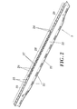
- Figure 2 shows how the second element 2 has a main part 21 extending longitudinally and which is configured to be housed in the longitudinal housing of the first element 1, between its walls 11.
- Two flanges 22 provided with rectangular lugs 23 extend along the main part 21, such lugs being configured to be introduced in the through holes 14 of the flanges 13 of the first element 1, to allow the first element and the second element to couple to one another by tongue and groove coupling, which facilitates handling the assembly. Therefore, and as can be deduced from Figure 3, since the first element 1 and the second element 2 are coupled, part of the outer surface of the side reinforcing element comprises the flanges 22 and the back of the main part 21 of the second element 2.
- the main part 21 of the second element 2 comprises two walls 24 joined by a plurality of partitions (25, 26, 27).
- the partitions of the second element are arranged with greater density in the central section 28 than they are in the end sections 29, such that the central section 28 has greater resistance against a side impact than the end sections 29.
- the central section comprises partitions 26 oriented perpendicularly in relation to the walls 24 and partitions 27 oriented non-perpendicularly in relation to the walls 24, whereas all the partitions 25 in the end sections 29 are oriented perpendicularly in relation to the walls 24.
- the invention is not limited to the specific embodiments that have been describe, but it also includes, for example, the variants that can be carried out by a person skilled in the art (for example in terms of choosing the materials, size, components, configuration, etc.), within the scope of the claims.
Landscapes
- Engineering & Computer Science (AREA)
- Mechanical Engineering (AREA)
- Body Structure For Vehicles (AREA)
Applications Claiming Priority (1)
| Application Number | Priority Date | Filing Date | Title |
|---|---|---|---|
| PCT/ES2005/000295 WO2006125833A1 (es) | 2005-05-25 | 2005-05-25 | Elemento de refuerzo lateral para puertas de vehículos automóviles |
Publications (2)
| Publication Number | Publication Date |
|---|---|
| EP1884385A1 true EP1884385A1 (de) | 2008-02-06 |
| EP1884385B1 EP1884385B1 (de) | 2008-12-17 |
Family
ID=37451646
Family Applications (1)
| Application Number | Title | Priority Date | Filing Date |
|---|---|---|---|
| EP05752222A Expired - Lifetime EP1884385B1 (de) | 2005-05-25 | 2005-05-25 | Seitliche verstärkung für kraftfahrzeugtüren |
Country Status (5)
| Country | Link |
|---|---|
| EP (1) | EP1884385B1 (de) |
| AT (1) | ATE417754T1 (de) |
| DE (1) | DE602005011866D1 (de) |
| ES (1) | ES2318499T3 (de) |
| WO (1) | WO2006125833A1 (de) |
Families Citing this family (1)
| Publication number | Priority date | Publication date | Assignee | Title |
|---|---|---|---|---|
| DE102008007556A1 (de) * | 2008-02-05 | 2009-08-06 | Daimler Ag | Hybridbauteil für einen Kraftwagen |
Family Cites Families (5)
| Publication number | Priority date | Publication date | Assignee | Title |
|---|---|---|---|---|
| EP0685355A1 (de) * | 1994-05-30 | 1995-12-06 | Schade Kg | Aufprallträger |
| US6421979B1 (en) * | 1999-09-16 | 2002-07-23 | Basf Aktiengesellschaft | Composite constructional element |
| FR2803899B1 (fr) * | 2000-01-17 | 2002-04-05 | Ecia Equip Composants Ind Auto | Element structurel comprenant un corps et des nervures de renfort et vehicule automobile correspondant |
| US6679540B1 (en) * | 2003-03-07 | 2004-01-20 | Trim Trends Co., Llc | Epoxy bonded laminate door beam |
| DE102004049397A1 (de) * | 2003-10-08 | 2005-06-09 | Behr Gmbh & Co. Kg | Bauteil und Verwendung eines derartigen Bauteils sowie Verfahren zur Herstellung eines Bauteils |
-
2005
- 2005-05-25 AT AT05752222T patent/ATE417754T1/de active
- 2005-05-25 EP EP05752222A patent/EP1884385B1/de not_active Expired - Lifetime
- 2005-05-25 DE DE602005011866T patent/DE602005011866D1/de not_active Expired - Lifetime
- 2005-05-25 WO PCT/ES2005/000295 patent/WO2006125833A1/es not_active Ceased
- 2005-05-25 ES ES05752222T patent/ES2318499T3/es not_active Expired - Lifetime
Non-Patent Citations (1)
| Title |
|---|
| See references of WO2006125833A1 * |
Also Published As
| Publication number | Publication date |
|---|---|
| EP1884385B1 (de) | 2008-12-17 |
| WO2006125833A1 (es) | 2006-11-30 |
| ES2318499T3 (es) | 2009-05-01 |
| DE602005011866D1 (de) | 2009-01-29 |
| ATE417754T1 (de) | 2009-01-15 |
Similar Documents
| Publication | Publication Date | Title |
|---|---|---|
| US10081395B2 (en) | Interconnection-type vehicle body structure | |
| US4428157A (en) | Door especially for motor vehicles | |
| JP4546496B2 (ja) | 自動車用バンパービーム | |
| EP2330016B1 (de) | 'B'- Säulenanordnung für Kraftfahrzeuge | |
| JP6156291B2 (ja) | 車両用ドア構造 | |
| US20180057062A1 (en) | Motor Vehicle | |
| CN105992712B (zh) | 车门内饰用扶手构造 | |
| DE102009032855A1 (de) | Stirnwandoberteilstruktur eines Fahrzeugs | |
| KR20150016506A (ko) | 차량용 시트 쿠션 프레임 | |
| EP3733484B1 (de) | Frontkarosserie eines fahrzeugs | |
| WO2018021422A1 (ja) | 衝撃吸収部材 | |
| DE102010036475A1 (de) | Stoßfängeraufsatz, Stoßfängeranordnung und Kraftfahrzeug | |
| EP1908650A1 (de) | Verformbares Teil für die Frontpartie eines Fahrzeugs | |
| EP2106355B1 (de) | Fahrzeugtürstruktur | |
| WO2002068232A1 (en) | Structural member of automobile and automobile body comprising it | |
| EP2708446B1 (de) | Struktur für den vorderteil einer fahrzeugkarosserie | |
| JP2011518717A (ja) | 車両用衝撃ガードビーム | |
| EP1884385B1 (de) | Seitliche verstärkung für kraftfahrzeugtüren | |
| EP1324900A1 (de) | Gehäuse für einen aufblasbaren gassack eines kraftfahrzeuges | |
| US20070035116A1 (en) | Rollover protection device | |
| EP3374249B1 (de) | Strukturbauteil für ein kraftfahrzeug | |
| EP1688318B1 (de) | Überrollschutzsystem für Kraftfahrzeuge mit einem Überrollkörper, dessen Bügelkopf U-förmig gerundet ist | |
| EP1803632A1 (de) | Rahmenverstärkungsglied | |
| DE102004030689A1 (de) | Querträger | |
| DE102010036985A1 (de) | Deformationselement |
Legal Events
| Date | Code | Title | Description |
|---|---|---|---|
| PUAI | Public reference made under article 153(3) epc to a published international application that has entered the european phase |
Free format text: ORIGINAL CODE: 0009012 |
|
| 17P | Request for examination filed |
Effective date: 20071123 |
|
| AK | Designated contracting states |
Kind code of ref document: A1 Designated state(s): AT BE BG CH CY CZ DE DK EE ES FI FR GB GR HU IE IS IT LI LT LU MC NL PL PT RO SE SI SK TR |
|
| GRAP | Despatch of communication of intention to grant a patent |
Free format text: ORIGINAL CODE: EPIDOSNIGR1 |
|
| DAX | Request for extension of the european patent (deleted) | ||
| GRAS | Grant fee paid |
Free format text: ORIGINAL CODE: EPIDOSNIGR3 |
|
| GRAA | (expected) grant |
Free format text: ORIGINAL CODE: 0009210 |
|
| AK | Designated contracting states |
Kind code of ref document: B1 Designated state(s): AT BE BG CH CY CZ DE DK EE ES FI FR GB GR HU IE IS IT LI LT LU MC NL PL PT RO SE SI SK TR |
|
| REG | Reference to a national code |
Ref country code: GB Ref legal event code: FG4D |
|
| REG | Reference to a national code |
Ref country code: CH Ref legal event code: EP |
|
| REG | Reference to a national code |
Ref country code: IE Ref legal event code: FG4D |
|
| REF | Corresponds to: |
Ref document number: 602005011866 Country of ref document: DE Date of ref document: 20090129 Kind code of ref document: P |
|
| PG25 | Lapsed in a contracting state [announced via postgrant information from national office to epo] |
Ref country code: LT Free format text: LAPSE BECAUSE OF FAILURE TO SUBMIT A TRANSLATION OF THE DESCRIPTION OR TO PAY THE FEE WITHIN THE PRESCRIBED TIME-LIMIT Effective date: 20081217 |
|
| REG | Reference to a national code |
Ref country code: ES Ref legal event code: FG2A Ref document number: 2318499 Country of ref document: ES Kind code of ref document: T3 |
|
| PG25 | Lapsed in a contracting state [announced via postgrant information from national office to epo] |
Ref country code: PL Free format text: LAPSE BECAUSE OF FAILURE TO SUBMIT A TRANSLATION OF THE DESCRIPTION OR TO PAY THE FEE WITHIN THE PRESCRIBED TIME-LIMIT Effective date: 20081217 Ref country code: NL Free format text: LAPSE BECAUSE OF FAILURE TO SUBMIT A TRANSLATION OF THE DESCRIPTION OR TO PAY THE FEE WITHIN THE PRESCRIBED TIME-LIMIT Effective date: 20081217 Ref country code: FI Free format text: LAPSE BECAUSE OF FAILURE TO SUBMIT A TRANSLATION OF THE DESCRIPTION OR TO PAY THE FEE WITHIN THE PRESCRIBED TIME-LIMIT Effective date: 20081217 Ref country code: SI Free format text: LAPSE BECAUSE OF FAILURE TO SUBMIT A TRANSLATION OF THE DESCRIPTION OR TO PAY THE FEE WITHIN THE PRESCRIBED TIME-LIMIT Effective date: 20081217 |
|
| NLV1 | Nl: lapsed or annulled due to failure to fulfill the requirements of art. 29p and 29m of the patents act | ||
| PG25 | Lapsed in a contracting state [announced via postgrant information from national office to epo] |
Ref country code: EE Free format text: LAPSE BECAUSE OF FAILURE TO SUBMIT A TRANSLATION OF THE DESCRIPTION OR TO PAY THE FEE WITHIN THE PRESCRIBED TIME-LIMIT Effective date: 20081217 Ref country code: BG Free format text: LAPSE BECAUSE OF FAILURE TO SUBMIT A TRANSLATION OF THE DESCRIPTION OR TO PAY THE FEE WITHIN THE PRESCRIBED TIME-LIMIT Effective date: 20090317 Ref country code: RO Free format text: LAPSE BECAUSE OF FAILURE TO SUBMIT A TRANSLATION OF THE DESCRIPTION OR TO PAY THE FEE WITHIN THE PRESCRIBED TIME-LIMIT Effective date: 20081217 |
|
| PG25 | Lapsed in a contracting state [announced via postgrant information from national office to epo] |
Ref country code: CZ Free format text: LAPSE BECAUSE OF FAILURE TO SUBMIT A TRANSLATION OF THE DESCRIPTION OR TO PAY THE FEE WITHIN THE PRESCRIBED TIME-LIMIT Effective date: 20081217 Ref country code: IS Free format text: LAPSE BECAUSE OF FAILURE TO SUBMIT A TRANSLATION OF THE DESCRIPTION OR TO PAY THE FEE WITHIN THE PRESCRIBED TIME-LIMIT Effective date: 20090417 Ref country code: SE Free format text: LAPSE BECAUSE OF FAILURE TO SUBMIT A TRANSLATION OF THE DESCRIPTION OR TO PAY THE FEE WITHIN THE PRESCRIBED TIME-LIMIT Effective date: 20090317 Ref country code: PT Free format text: LAPSE BECAUSE OF FAILURE TO SUBMIT A TRANSLATION OF THE DESCRIPTION OR TO PAY THE FEE WITHIN THE PRESCRIBED TIME-LIMIT Effective date: 20090518 |
|
| PG25 | Lapsed in a contracting state [announced via postgrant information from national office to epo] |
Ref country code: SK Free format text: LAPSE BECAUSE OF FAILURE TO SUBMIT A TRANSLATION OF THE DESCRIPTION OR TO PAY THE FEE WITHIN THE PRESCRIBED TIME-LIMIT Effective date: 20081217 |
|
| PLBE | No opposition filed within time limit |
Free format text: ORIGINAL CODE: 0009261 |
|
| STAA | Information on the status of an ep patent application or granted ep patent |
Free format text: STATUS: NO OPPOSITION FILED WITHIN TIME LIMIT |
|
| PG25 | Lapsed in a contracting state [announced via postgrant information from national office to epo] |
Ref country code: DK Free format text: LAPSE BECAUSE OF FAILURE TO SUBMIT A TRANSLATION OF THE DESCRIPTION OR TO PAY THE FEE WITHIN THE PRESCRIBED TIME-LIMIT Effective date: 20081217 |
|
| 26N | No opposition filed |
Effective date: 20090918 |
|
| PG25 | Lapsed in a contracting state [announced via postgrant information from national office to epo] |
Ref country code: MC Free format text: LAPSE BECAUSE OF NON-PAYMENT OF DUE FEES Effective date: 20090531 |
|
| REG | Reference to a national code |
Ref country code: CH Ref legal event code: PL |
|
| PG25 | Lapsed in a contracting state [announced via postgrant information from national office to epo] |
Ref country code: LI Free format text: LAPSE BECAUSE OF NON-PAYMENT OF DUE FEES Effective date: 20090531 Ref country code: CH Free format text: LAPSE BECAUSE OF NON-PAYMENT OF DUE FEES Effective date: 20090531 |
|
| PG25 | Lapsed in a contracting state [announced via postgrant information from national office to epo] |
Ref country code: IE Free format text: LAPSE BECAUSE OF NON-PAYMENT OF DUE FEES Effective date: 20090525 |
|
| PG25 | Lapsed in a contracting state [announced via postgrant information from national office to epo] |
Ref country code: GR Free format text: LAPSE BECAUSE OF FAILURE TO SUBMIT A TRANSLATION OF THE DESCRIPTION OR TO PAY THE FEE WITHIN THE PRESCRIBED TIME-LIMIT Effective date: 20090318 |
|
| PG25 | Lapsed in a contracting state [announced via postgrant information from national office to epo] |
Ref country code: LU Free format text: LAPSE BECAUSE OF NON-PAYMENT OF DUE FEES Effective date: 20090525 |
|
| PG25 | Lapsed in a contracting state [announced via postgrant information from national office to epo] |
Ref country code: HU Free format text: LAPSE BECAUSE OF FAILURE TO SUBMIT A TRANSLATION OF THE DESCRIPTION OR TO PAY THE FEE WITHIN THE PRESCRIBED TIME-LIMIT Effective date: 20090618 |
|
| PG25 | Lapsed in a contracting state [announced via postgrant information from national office to epo] |
Ref country code: TR Free format text: LAPSE BECAUSE OF FAILURE TO SUBMIT A TRANSLATION OF THE DESCRIPTION OR TO PAY THE FEE WITHIN THE PRESCRIBED TIME-LIMIT Effective date: 20081217 |
|
| PG25 | Lapsed in a contracting state [announced via postgrant information from national office to epo] |
Ref country code: CY Free format text: LAPSE BECAUSE OF FAILURE TO SUBMIT A TRANSLATION OF THE DESCRIPTION OR TO PAY THE FEE WITHIN THE PRESCRIBED TIME-LIMIT Effective date: 20081217 |
|
| PGFP | Annual fee paid to national office [announced via postgrant information from national office to epo] |
Ref country code: AT Payment date: 20140515 Year of fee payment: 10 |
|
| PGFP | Annual fee paid to national office [announced via postgrant information from national office to epo] |
Ref country code: BE Payment date: 20140523 Year of fee payment: 10 |
|
| REG | Reference to a national code |
Ref country code: AT Ref legal event code: MM01 Ref document number: 417754 Country of ref document: AT Kind code of ref document: T Effective date: 20150525 |
|
| PG25 | Lapsed in a contracting state [announced via postgrant information from national office to epo] |
Ref country code: AT Free format text: LAPSE BECAUSE OF NON-PAYMENT OF DUE FEES Effective date: 20150525 |
|
| REG | Reference to a national code |
Ref country code: FR Ref legal event code: PLFP Year of fee payment: 12 |
|
| REG | Reference to a national code |
Ref country code: FR Ref legal event code: PLFP Year of fee payment: 13 |
|
| PG25 | Lapsed in a contracting state [announced via postgrant information from national office to epo] |
Ref country code: BE Free format text: LAPSE BECAUSE OF NON-PAYMENT OF DUE FEES Effective date: 20150531 |
|
| REG | Reference to a national code |
Ref country code: FR Ref legal event code: PLFP Year of fee payment: 14 |
|
| PGFP | Annual fee paid to national office [announced via postgrant information from national office to epo] |
Ref country code: FR Payment date: 20210524 Year of fee payment: 17 Ref country code: DE Payment date: 20210517 Year of fee payment: 17 Ref country code: IT Payment date: 20210504 Year of fee payment: 17 |
|
| PGFP | Annual fee paid to national office [announced via postgrant information from national office to epo] |
Ref country code: GB Payment date: 20210524 Year of fee payment: 17 Ref country code: ES Payment date: 20210603 Year of fee payment: 17 |
|
| REG | Reference to a national code |
Ref country code: DE Ref legal event code: R119 Ref document number: 602005011866 Country of ref document: DE |
|
| GBPC | Gb: european patent ceased through non-payment of renewal fee |
Effective date: 20220525 |
|
| PG25 | Lapsed in a contracting state [announced via postgrant information from national office to epo] |
Ref country code: FR Free format text: LAPSE BECAUSE OF NON-PAYMENT OF DUE FEES Effective date: 20220531 |
|
| PG25 | Lapsed in a contracting state [announced via postgrant information from national office to epo] |
Ref country code: GB Free format text: LAPSE BECAUSE OF NON-PAYMENT OF DUE FEES Effective date: 20220525 Ref country code: DE Free format text: LAPSE BECAUSE OF NON-PAYMENT OF DUE FEES Effective date: 20221201 |
|
| REG | Reference to a national code |
Ref country code: ES Ref legal event code: FD2A Effective date: 20230630 |
|
| PG25 | Lapsed in a contracting state [announced via postgrant information from national office to epo] |
Ref country code: IT Free format text: LAPSE BECAUSE OF NON-PAYMENT OF DUE FEES Effective date: 20220525 Ref country code: ES Free format text: LAPSE BECAUSE OF NON-PAYMENT OF DUE FEES Effective date: 20220526 |