EP1884392A2 - Dichtungsstreifen mit Metalleinlage - Google Patents
Dichtungsstreifen mit Metalleinlage Download PDFInfo
- Publication number
- EP1884392A2 EP1884392A2 EP07013495A EP07013495A EP1884392A2 EP 1884392 A2 EP1884392 A2 EP 1884392A2 EP 07013495 A EP07013495 A EP 07013495A EP 07013495 A EP07013495 A EP 07013495A EP 1884392 A2 EP1884392 A2 EP 1884392A2
- Authority
- EP
- European Patent Office
- Prior art keywords
- side wall
- insert
- weather strip
- curved parts
- corresponding part
- Prior art date
- Legal status (The legal status is an assumption and is not a legal conclusion. Google has not performed a legal analysis and makes no representation as to the accuracy of the status listed.)
- Granted
Links
Images


Classifications
-
- B—PERFORMING OPERATIONS; TRANSPORTING
- B60—VEHICLES IN GENERAL
- B60J—WINDOWS, WINDSCREENS, NON-FIXED ROOFS, DOORS, OR SIMILAR DEVICES FOR VEHICLES; REMOVABLE EXTERNAL PROTECTIVE COVERINGS SPECIALLY ADAPTED FOR VEHICLES
- B60J10/00—Sealing arrangements
- B60J10/20—Sealing arrangements characterised by the shape
- B60J10/24—Sealing arrangements characterised by the shape having tubular parts
-
- B—PERFORMING OPERATIONS; TRANSPORTING
- B60—VEHICLES IN GENERAL
- B60J—WINDOWS, WINDSCREENS, NON-FIXED ROOFS, DOORS, OR SIMILAR DEVICES FOR VEHICLES; REMOVABLE EXTERNAL PROTECTIVE COVERINGS SPECIALLY ADAPTED FOR VEHICLES
- B60J10/00—Sealing arrangements
- B60J10/15—Sealing arrangements characterised by the material
- B60J10/18—Sealing arrangements characterised by the material provided with reinforcements or inserts
-
- B—PERFORMING OPERATIONS; TRANSPORTING
- B60—VEHICLES IN GENERAL
- B60J—WINDOWS, WINDSCREENS, NON-FIXED ROOFS, DOORS, OR SIMILAR DEVICES FOR VEHICLES; REMOVABLE EXTERNAL PROTECTIVE COVERINGS SPECIALLY ADAPTED FOR VEHICLES
- B60J10/00—Sealing arrangements
- B60J10/80—Sealing arrangements specially adapted for opening panels, e.g. doors
-
- Y—GENERAL TAGGING OF NEW TECHNOLOGICAL DEVELOPMENTS; GENERAL TAGGING OF CROSS-SECTIONAL TECHNOLOGIES SPANNING OVER SEVERAL SECTIONS OF THE IPC; TECHNICAL SUBJECTS COVERED BY FORMER USPC CROSS-REFERENCE ART COLLECTIONS [XRACs] AND DIGESTS
- Y10—TECHNICAL SUBJECTS COVERED BY FORMER USPC
- Y10T—TECHNICAL SUBJECTS COVERED BY FORMER US CLASSIFICATION
- Y10T428/00—Stock material or miscellaneous articles
- Y10T428/12—All metal or with adjacent metals
- Y10T428/12389—All metal or with adjacent metals having variation in thickness
-
- Y—GENERAL TAGGING OF NEW TECHNOLOGICAL DEVELOPMENTS; GENERAL TAGGING OF CROSS-SECTIONAL TECHNOLOGIES SPANNING OVER SEVERAL SECTIONS OF THE IPC; TECHNICAL SUBJECTS COVERED BY FORMER USPC CROSS-REFERENCE ART COLLECTIONS [XRACs] AND DIGESTS
- Y10—TECHNICAL SUBJECTS COVERED BY FORMER USPC
- Y10T—TECHNICAL SUBJECTS COVERED BY FORMER US CLASSIFICATION
- Y10T428/00—Stock material or miscellaneous articles
- Y10T428/24—Structurally defined web or sheet [e.g., overall dimension, etc.]
- Y10T428/2419—Fold at edge
- Y10T428/24198—Channel-shaped edge component [e.g., binding, etc.]
-
- Y—GENERAL TAGGING OF NEW TECHNOLOGICAL DEVELOPMENTS; GENERAL TAGGING OF CROSS-SECTIONAL TECHNOLOGIES SPANNING OVER SEVERAL SECTIONS OF THE IPC; TECHNICAL SUBJECTS COVERED BY FORMER USPC CROSS-REFERENCE ART COLLECTIONS [XRACs] AND DIGESTS
- Y10—TECHNICAL SUBJECTS COVERED BY FORMER USPC
- Y10T—TECHNICAL SUBJECTS COVERED BY FORMER US CLASSIFICATION
- Y10T428/00—Stock material or miscellaneous articles
- Y10T428/24—Structurally defined web or sheet [e.g., overall dimension, etc.]
- Y10T428/24942—Structurally defined web or sheet [e.g., overall dimension, etc.] including components having same physical characteristic in differing degree
- Y10T428/2495—Thickness [relative or absolute]
Definitions
- the present invention relates to a weather strip configured so that an insert is embedded in a trim portion.
- a weather strip having a trim portion is provided on a flange formed along the peripheral part of a door opening of a vehicle, such as an automobile.
- the weather strip has a trimportion, which has a holding lip held by being fit into the flange formed along the peripheral part of the door opening, and also has a hollow seal portion provided to protrude from the trim portion.
- the trim portion has a connecting portion, which connects a vehicle interior side wall, a vehicle exterior side wall, and both side walls, and is substantially-U-shaped in cross section.
- an insert 90 is embedded in the trim portion.
- an insert 90 has a plurality of strip-like piece portions 91 disposed substantially parallel to one another and bond portions 92 (e.g., a center bond portion placed in the connecting portion) that connect the piece portions 91 to one another.
- bond portions 92 e.g., a center bond portion placed in the connecting portion
- FIG. 8 illustrates the insert 90 that is in a state before each of the piece portions 91 is subjected to bending-work and is formed into a substantially U-shape.
- the trim portion When a weather strip is mounted on the flange, the trim portion is fit thereinto.
- a mounted state, in which the weather strip is mounted thereon, is maintained basically by an elastic force of the holding lip portion or a bonding force of the insert. Additionally, when a door is closed, an edge portion of the door abuts against the seal portion. Thus, the seal portion is crush-deformed to seal between the door and a body of the vehicle.
- An object of the invention is to provide a weather strip enabled to suppress reduction of the strength and the bonding force, while reducing the weight thereof.
- an end part of at least one of the vehicle interior side wall corresponding part and the vehicle exterior side wall corresponding part is cut off at predetermined intervals.
- the weather strip can be further lightened.
- obj ects to be cut are end parts of the vehicle interior side wall corresponding part and the vehicle exterior side wall corresponding part. Additionally, the end parts are cut at the predetermined intervals (e.g., every two end parts or every three end parts). This does not much affect the strength and the stiffness.
- a weather strip 4 is provided on a peripheral part of a body-side door opening 3 corresponding to a side door 2 of an automobile 1.
- the weather strip 4 according to the present embodiment is mounted on the peripheral part of the door opening 3 other than a lower part thereof.
- the entire weather strip 4 is formed by extrusion-molding.
- the weather strip 4 has a trim portion 5 and a seal portion 6.
- the trim portion 5 has a vehicle interior side wall 11, a vehicle exterior side wall 12, and a curved-cross section connecting portion 13 connecting both the side walls 11 and 12.
- the trim portion 5 is substantially U-shaped in cross section, as a whole.
- the trim portion 5 is made of EPDM (ethylene-propylene-diene-copolymer) solid rubber.
- a metal insert 14 (in the present embodiment, the insert 14 is made of a cold rolled steel sheet (e.g., SPCC-4D)) is embedded in the trim portion 5.
- a plurality of holding lip portions 15 extending toward the inside (i.e., the vehicle interior side in the direction of width of the vehicle) of the trim portion 5 are integrally formed on the inner surface of the vehicle exterior side wall 12.
- a holding lip portion 16 extending toward the inside (i.e., the vehicle exterior side in the direction of width of the vehicle) of the trim portion 5 is formed on the inner surface of the vehicle interior side wall 11 integrally therewith.
- a cover lip 17 used to cover end portions of interior parts (not shown), such as a garnish, is formed integrally with the connecting portion 13.
- the seal portion 6 is provided on the vehicle exterior side wall 12 to protrude therefrom to the vehicle exterior side.
- the seal portion 6 is made of EPDM sponge rubber.
- the seal portion 6 may be made mainly of EPDM sponge rubber so that coating-film made of EPDM solid rubber is formed on a surface layer side. Additionally, when the door 2 is closed, the seal portion 6 is crush-deformed to seal between the door 2 and the body of the automobile 1.
- the weather strip 4 is mounted on the peripheral part of the body-side door opening 3 (see FIG. 2) by fitting the trim portion 5 into the door opening 3. More specifically, as illustrated in FIG. 1, the body ha san inner panel 21 and an outer panel 22. Basically, a flange 23 is formed by joining peripheral part portions of both the panels 21 and 22 to each other (apparently, a plate-like reinforcement can be provided between both the panels 21 and 22 so as to increase the strength) . Then, the trim portion 5 is fit into the flange 23. Basically, the mounted state of the weather strip is maintained by the elastic forces of the holding lips 15 and 16 or the bonding force of the insert 14.
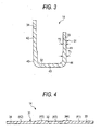
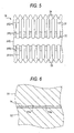
- Inserts of the center bond type shown in FIGS. 3, 4, and 5 are used as the insert 14 in the present embodiment (FIGS. 4 and 5 illustrate a state before the insert is subjected to bending-work). That is, the insert 14 has a plurality of strip-like piece portions 31 disposed substantially parallel to one another, a center bond portion 32 connecting the piece portions 31 to one another substantially at the central portion, and side bond portions 33 and 34 connected to each other substantially at both end portions thereof.
- a reason for connecting the side bond portions 33 and 34 to each other at the extrusion-molding is that the insert 14 is linearly fed.
- a reason for cutting the side bond portions 33 and 34 after subjected to the bending-work is that the mountability of the trim portion 5 by bending is enhanced.
- the center bond portion 32 corresponds to the "bond portion".
- each of the piece portions 31 is bent, together with the trim portion 5, substantially like a letter "U". That is, each of the piece portions 31 has a vehicle interior side wall corresponding part 41 corresponding to the vehicle interior side wall 11, a vehicle exterior side wall corresponding part 42 corresponding to the vehicle exterior side wall 12, and a connecting portion corresponding part 43 corresponding to the connecting portion 13.
- Each of the piece portions 31 is substantially U-shaped in cross section through the bending-work.
- a continuously connecting part between the vehicle interior side wall corresponding part 41 and the connecting portion corresponding part 43 and a continuously connecting part between the vehicle exterior side wall corresponding part 42 and the connecting portion corresponding part 43 are the curved parts 44 and 45, respectively.
- the thickness of each of the remaining parts except for both the curved parts 44 and 45 is thin.
- the thickness T1 of each of both the curved parts 44 and 45 is 0.5 mm, while the thickness T2 of each of the remaining parts (including the center bond portion 32 and the side bond portions 33 and 34) other than the curved parts 44 and 45 is 0.4 mm.
- such an insert 14 is obtained as follows. First, in a process of reversely feeding a thin-sheet-like cold rolled steel sheet (SPCC-4D) along the longitudinal direction, cuts (or slits) are formed therein.
- the steel sheet, in which the cuts are formed, is guided to a group of paired upper and lower rolling mill rollers.
- the group of rolling mill rollers is used to make the steel sheet thin and to evenly draw out the thin steel sheet.
- the steel sheet passed through the rolling mill rollers is drawn out at the cuts and is formed into a shape, in which the piece portions 31 are separated fromone another, as illustrated in FIG. 5. Consequently, a plurality of strip-like piece portions 31 are formed at predetermined intervals.
- FIG. 6 is a schematic cross-sectional view illustrating an example of the rolling mill rollers.
- the rolling mill rollers include an upper roller 51 and a lower roller 52.
- An outer peripheral surface of the lower roller 52 is shaped flat, while a step-like part 51a is formed on the upper roller 51. Additionally, the aforementioned difference in thickness is provided by the step-like part 51a. That is, parts, in each of which the gap between both the rollers 51 and 52 is relatively large, (corresponding to the curved parts 44 and 45) are formed to be relatively thick. The remaining parts, in which the gap between both the rollers 51 and 52 is relatively small, are formed to be relatively thin.
- the weather strip 4 according to the present embodiment are manufactured through an extrusion step, a vulcanization step, a bending step, and a cutting step. That is, in the extrusion step, unvulcanized rubber is extruded while the flat-sheet-like insert 14, which has been extended by applying pressure thereto, is continuously supplied from a shaped hole formed in a die (not shown) constituting an extruder. At that time, the part corresponding to the trim portion 5 is extruded in a state in which both end portions of this part are spread like a flat sheet or substantially like a letter "V".
- the extruded unvulcanized rubber is continuously guided into a vulcanizer (or a heating zone (not shown)), in which vulcanization is performed on the unvulcanized rubber.
- a vulcanized precursor of the weather strip 4 is guided to a bending-work apparatus (not shown) . Then, the bending-work of the precursor is performed so that both end portions of the part corresponding to the trim portion 5 are narrowed. Consequently, a trimportion 5 having a substantially-U-shaped cross section is formed. At that time, as described above, the bending-work of the insert 14 is performed. Thus, the aforementioned curved parts 44 and 45 are formed. Subsequently, the insert 14 is passed through an insert separator (not shown), so that the aforementioned side bond portions 33 and 34. are separated therefrom. Then, the insert 14 is cut at a cutter (not shown) into parts which have a predetermined length. Consequently, the aforementioned weather strip 4 is obtained.
- the thickness T2 of each of the remaining parts except for both the curved parts 44 and 45 is thin.
- the entire insert 14, thus, the entire weather strip 4 can be lightened by reducing the thickness of the insert 14, except for both the curved parts 44 and 45 (T2 0.4 mm) .
- the weather strip can obtain two opposite advantages at a time, that is, the weather strip can be lightened, while the weather strip can have the predetermined strength.
- the insert 14 is made of a cold rolled steel sheet (e.g., SPCC-4D) and is formed by extending the cold rolled steel sheet by applying pressure thereto using the group of the rolling mill rollers (e.g., the upper and lower rollers 51 and 52).
- the insert 14 is manufactured by extending a plate-like material by applying pressure thereto using the rolling mill rollers. In this case, it is necessary to provide a difference in thickness between a part, which corresponds to each of both the curved parts 44 and 45, and each of the remaining parts other than both the curved parts 44 and 45.
- a predetermined step-like part 51a is formed on the surface of the upper roller 51. Then, a rolling process is performed on the plate-like material. Consequently, the above-described insert 14 can accurately and stably be obtained with a relatively simple configuration.
- the invention is not limited to the embodiments described in the foregoing description.
- the invention can be carried out as follows.
- other applications and alterations of the invention, which are not exemplified in the following description, can be made.
Landscapes
- Engineering & Computer Science (AREA)
- Mechanical Engineering (AREA)
- Seal Device For Vehicle (AREA)
Applications Claiming Priority (1)
| Application Number | Priority Date | Filing Date | Title |
|---|---|---|---|
| JP2006203409A JP4760591B2 (ja) | 2006-07-26 | 2006-07-26 | ウエザストリップ |
Publications (3)
| Publication Number | Publication Date |
|---|---|
| EP1884392A2 true EP1884392A2 (de) | 2008-02-06 |
| EP1884392A3 EP1884392A3 (de) | 2008-08-13 |
| EP1884392B1 EP1884392B1 (de) | 2010-06-30 |
Family
ID=38521219
Family Applications (1)
| Application Number | Title | Priority Date | Filing Date |
|---|---|---|---|
| EP07013495A Ceased EP1884392B1 (de) | 2006-07-26 | 2007-07-10 | Dichtungsstreifen mit Metalleinlage |
Country Status (5)
| Country | Link |
|---|---|
| US (1) | US7687133B2 (de) |
| EP (1) | EP1884392B1 (de) |
| JP (1) | JP4760591B2 (de) |
| CN (1) | CN100544987C (de) |
| DE (1) | DE602007007401D1 (de) |
Cited By (1)
| Publication number | Priority date | Publication date | Assignee | Title |
|---|---|---|---|---|
| GB2532120A (en) * | 2014-10-29 | 2016-05-11 | Gm Global Tech Operations Llc | Insert for a motor vehicle seal |
Families Citing this family (7)
| Publication number | Priority date | Publication date | Assignee | Title |
|---|---|---|---|---|
| JP4752674B2 (ja) | 2006-08-21 | 2011-08-17 | 豊田合成株式会社 | ウエザストリップの製造方法 |
| JP5556611B2 (ja) * | 2009-12-25 | 2014-07-23 | 豊田合成株式会社 | インサートの製造方法及びそのインサートを有する長尺成形品の製造方法 |
| KR101251966B1 (ko) * | 2010-08-19 | 2013-04-08 | 주식회사 디엠씨 | 자동차용 사이드 웨더스트립 |
| DE102010035522A1 (de) * | 2010-08-25 | 2012-03-01 | Hochland Se | Vorrichtung zur Herstellung von Schmelzkäseportionen |
| JP5761567B2 (ja) * | 2010-09-28 | 2015-08-12 | 豊田合成株式会社 | 自動車用ウエザストリップ |
| US9902248B2 (en) * | 2013-07-03 | 2018-02-27 | Honda Motor Co., Ltd. | Vehicle-use seal structure |
| JP7145720B2 (ja) * | 2018-10-11 | 2022-10-03 | 西川ゴム工業株式会社 | ウェザストリップ |
Family Cites Families (13)
| Publication number | Priority date | Publication date | Assignee | Title |
|---|---|---|---|---|
| US4188424A (en) | 1976-12-21 | 1980-02-12 | Toyoda Gosei Co., Ltd. | Metal carrier for trim |
| GB2028407B (en) | 1978-07-17 | 1982-06-16 | Toyoda Gosei Kk | Channel-shaped trim strip |
| JPS5936865B2 (ja) | 1979-05-31 | 1984-09-06 | 豊田合成株式会社 | トリムの製造方法 |
| US5783312A (en) * | 1996-12-19 | 1998-07-21 | The Gem City Engineering Co. | Expanded metal strip for reinforcing a resilient product |
| JPH1148879A (ja) | 1997-07-31 | 1999-02-23 | Toyo Tire & Rubber Co Ltd | 自動車用オープニングトリム |
| JP2000052892A (ja) * | 1998-08-06 | 2000-02-22 | Toyo Tire & Rubber Co Ltd | ウエザストリップ等の周縁部材及びその芯金並びに芯金の製造方法 |
| JP2001310687A (ja) * | 2000-04-27 | 2001-11-06 | Toyoda Gosei Co Ltd | トリム用インサート及びトリム |
| US6684574B2 (en) | 2000-10-31 | 2004-02-03 | Toyoda Gosei Co., Ltd. | Insert for trim, trim and weather strip for vehicle |
| DE60235940D1 (de) | 2001-07-13 | 2010-05-27 | Toyoda Gosei Kk | Dichtungsprofil und Verfahren zur dessen Herstellung |
| JP2003200791A (ja) * | 2001-10-29 | 2003-07-15 | Nippon Purai Kk | トリム用インサート及びトリム |
| US6889985B2 (en) * | 2003-01-31 | 2005-05-10 | Scovil Hanna Corporation | Core metal insert for weatherseals |
| DE102004005257B4 (de) | 2003-02-07 | 2005-09-15 | Toyoda Gosei Co., Ltd., Nishikasugai | Dichtungsstreifen |
| US7604766B2 (en) * | 2004-12-02 | 2009-10-20 | Scovil Hanna Corporation | Core metal insert with stress relief and method of making same |
-
2006
- 2006-07-26 JP JP2006203409A patent/JP4760591B2/ja active Active
-
2007
- 2007-07-10 DE DE602007007401T patent/DE602007007401D1/de active Active
- 2007-07-10 EP EP07013495A patent/EP1884392B1/de not_active Ceased
- 2007-07-20 US US11/878,137 patent/US7687133B2/en active Active
- 2007-07-26 CN CNB2007101363924A patent/CN100544987C/zh active Active
Cited By (1)
| Publication number | Priority date | Publication date | Assignee | Title |
|---|---|---|---|---|
| GB2532120A (en) * | 2014-10-29 | 2016-05-11 | Gm Global Tech Operations Llc | Insert for a motor vehicle seal |
Also Published As
| Publication number | Publication date |
|---|---|
| JP2008030525A (ja) | 2008-02-14 |
| DE602007007401D1 (de) | 2010-08-12 |
| JP4760591B2 (ja) | 2011-08-31 |
| US20080026196A1 (en) | 2008-01-31 |
| EP1884392A3 (de) | 2008-08-13 |
| CN101112866A (zh) | 2008-01-30 |
| CN100544987C (zh) | 2009-09-30 |
| US7687133B2 (en) | 2010-03-30 |
| EP1884392B1 (de) | 2010-06-30 |
Similar Documents
| Publication | Publication Date | Title |
|---|---|---|
| EP1884392B1 (de) | Dichtungsstreifen mit Metalleinlage | |
| US6070364A (en) | Flush glass seal insert with a belt-line extension | |
| US7735263B2 (en) | Weather strip for motor vehicle | |
| EP2551138B1 (de) | Dichtung für ein Fahrzeug und dazugehöriges Herstellungsverfahren | |
| EP2542432B1 (de) | Durch helle extrusion geformte koextrudierte rolle mit integrierten endformen | |
| JPH10181349A (ja) | ドアおよび窓みぞの組合せシール | |
| US20090121378A1 (en) | Heat fromad TPV co-extruded Header trim | |
| US6889985B2 (en) | Core metal insert for weatherseals | |
| US6370824B1 (en) | Automotive vehicle seal with decorative trim sealing surface | |
| US8793937B2 (en) | Weather strip for motor vehicle | |
| CN111196137A (zh) | 汽车车门用密封件及其制造方法 | |
| EP3095629B1 (de) | Fahrzeugdichtungselement | |
| US9174519B2 (en) | Weatherstrip assembly having a variable length shim | |
| JP3800045B2 (ja) | ウエザーストリップ及びその製造方法 | |
| JP3873677B2 (ja) | ウエザーストリップ、その製造方法及びその取付構造 | |
| JP2005014792A (ja) | トリム用インサート | |
| JP2009179078A (ja) | ウエザストリップ | |
| JP3800046B2 (ja) | ウエザーストリップの製造方法 | |
| EP4105049A1 (de) | Applikation mit randabdichtung | |
| JP6050695B2 (ja) | オープニングトリムの製造方法 | |
| JP2006335090A (ja) | トリム、ウエザストリップ及びそれらの製造方法 | |
| JP2010052507A (ja) | ウエザストリップ | |
| JP2008056020A (ja) | ウエザストリップ | |
| JP2008132849A (ja) | ウエザストリップ及びその製造方法 | |
| JP2008056021A (ja) | ウエザストリップ |
Legal Events
| Date | Code | Title | Description |
|---|---|---|---|
| PUAI | Public reference made under article 153(3) epc to a published international application that has entered the european phase |
Free format text: ORIGINAL CODE: 0009012 |
|
| 17P | Request for examination filed |
Effective date: 20070710 |
|
| AK | Designated contracting states |
Kind code of ref document: A2 Designated state(s): AT BE BG CH CY CZ DE DK EE ES FI FR GB GR HU IE IS IT LI LT LU LV MC MT NL PL PT RO SE SI SK TR |
|
| AX | Request for extension of the european patent |
Extension state: AL BA HR MK YU |
|
| RIN1 | Information on inventor provided before grant (corrected) |
Inventor name: TOKI, SATOSHI Inventor name: ARITAKE, MASANORI Inventor name: IWASA, NORIMASA |
|
| PUAL | Search report despatched |
Free format text: ORIGINAL CODE: 0009013 |
|
| AK | Designated contracting states |
Kind code of ref document: A3 Designated state(s): AT BE BG CH CY CZ DE DK EE ES FI FR GB GR HU IE IS IT LI LT LU LV MC MT NL PL PT RO SE SI SK TR |
|
| AX | Request for extension of the european patent |
Extension state: AL BA HR MK RS |
|
| AKX | Designation fees paid |
Designated state(s): DE FR GB |
|
| GRAP | Despatch of communication of intention to grant a patent |
Free format text: ORIGINAL CODE: EPIDOSNIGR1 |
|
| GRAS | Grant fee paid |
Free format text: ORIGINAL CODE: EPIDOSNIGR3 |
|
| GRAA | (expected) grant |
Free format text: ORIGINAL CODE: 0009210 |
|
| AK | Designated contracting states |
Kind code of ref document: B1 Designated state(s): DE FR GB |
|
| REG | Reference to a national code |
Ref country code: GB Ref legal event code: FG4D |
|
| REF | Corresponds to: |
Ref document number: 602007007401 Country of ref document: DE Date of ref document: 20100812 Kind code of ref document: P |
|
| PLBE | No opposition filed within time limit |
Free format text: ORIGINAL CODE: 0009261 |
|
| STAA | Information on the status of an ep patent application or granted ep patent |
Free format text: STATUS: NO OPPOSITION FILED WITHIN TIME LIMIT |
|
| 26N | No opposition filed |
Effective date: 20110331 |
|
| REG | Reference to a national code |
Ref country code: DE Ref legal event code: R097 Ref document number: 602007007401 Country of ref document: DE Effective date: 20110330 |
|
| REG | Reference to a national code |
Ref country code: GB Ref legal event code: 746 Effective date: 20120611 |
|
| REG | Reference to a national code |
Ref country code: DE Ref legal event code: R084 Ref document number: 602007007401 Country of ref document: DE Effective date: 20120530 |
|
| REG | Reference to a national code |
Ref country code: FR Ref legal event code: PLFP Year of fee payment: 10 |
|
| REG | Reference to a national code |
Ref country code: FR Ref legal event code: PLFP Year of fee payment: 11 |
|
| REG | Reference to a national code |
Ref country code: FR Ref legal event code: PLFP Year of fee payment: 12 |
|
| PGFP | Annual fee paid to national office [announced via postgrant information from national office to epo] |
Ref country code: GB Payment date: 20240530 Year of fee payment: 18 |
|
| PGFP | Annual fee paid to national office [announced via postgrant information from national office to epo] |
Ref country code: FR Payment date: 20240611 Year of fee payment: 18 |
|
| PGFP | Annual fee paid to national office [announced via postgrant information from national office to epo] |
Ref country code: DE Payment date: 20240529 Year of fee payment: 18 |
|
| REG | Reference to a national code |
Ref country code: DE Ref legal event code: R119 Ref document number: 602007007401 Country of ref document: DE |
|
| GBPC | Gb: european patent ceased through non-payment of renewal fee |
Effective date: 20250710 |
|
| PG25 | Lapsed in a contracting state [announced via postgrant information from national office to epo] |
Ref country code: GB Free format text: LAPSE BECAUSE OF NON-PAYMENT OF DUE FEES Effective date: 20250710 |
|
| PG25 | Lapsed in a contracting state [announced via postgrant information from national office to epo] |
Ref country code: DE Free format text: LAPSE BECAUSE OF NON-PAYMENT OF DUE FEES Effective date: 20260203 |
|
| PG25 | Lapsed in a contracting state [announced via postgrant information from national office to epo] |
Ref country code: FR Free format text: LAPSE BECAUSE OF NON-PAYMENT OF DUE FEES Effective date: 20250731 |