EP1884402A1 - Dispositif de levage et de pivotement pour hayon élévateur ou rampe de chargement - Google Patents
Dispositif de levage et de pivotement pour hayon élévateur ou rampe de chargement Download PDFInfo
- Publication number
- EP1884402A1 EP1884402A1 EP06015377A EP06015377A EP1884402A1 EP 1884402 A1 EP1884402 A1 EP 1884402A1 EP 06015377 A EP06015377 A EP 06015377A EP 06015377 A EP06015377 A EP 06015377A EP 1884402 A1 EP1884402 A1 EP 1884402A1
- Authority
- EP
- European Patent Office
- Prior art keywords
- lifting
- rotary motor
- tail lift
- motor shaft
- pivoting
- Prior art date
- Legal status (The legal status is an assumption and is not a legal conclusion. Google has not performed a legal analysis and makes no representation as to the accuracy of the status listed.)
- Withdrawn
Links
Images



Classifications
-
- B—PERFORMING OPERATIONS; TRANSPORTING
- B60—VEHICLES IN GENERAL
- B60P—VEHICLES ADAPTED FOR LOAD TRANSPORTATION OR TO TRANSPORT, TO CARRY, OR TO COMPRISE SPECIAL LOADS OR OBJECTS
- B60P1/00—Vehicles predominantly for transporting loads and modified to facilitate loading, consolidating the load, or unloading
- B60P1/44—Vehicles predominantly for transporting loads and modified to facilitate loading, consolidating the load, or unloading having a loading platform thereon raising the load to the level of the load-transporting element
- B60P1/4414—Vehicles predominantly for transporting loads and modified to facilitate loading, consolidating the load, or unloading having a loading platform thereon raising the load to the level of the load-transporting element and keeping the loading platform parallel to the ground when raising the load
-
- B—PERFORMING OPERATIONS; TRANSPORTING
- B60—VEHICLES IN GENERAL
- B60P—VEHICLES ADAPTED FOR LOAD TRANSPORTATION OR TO TRANSPORT, TO CARRY, OR TO COMPRISE SPECIAL LOADS OR OBJECTS
- B60P1/00—Vehicles predominantly for transporting loads and modified to facilitate loading, consolidating the load, or unloading
- B60P1/44—Vehicles predominantly for transporting loads and modified to facilitate loading, consolidating the load, or unloading having a loading platform thereon raising the load to the level of the load-transporting element
- B60P1/4471—General means for controlling movements of the loading platform, e.g. hydraulic systems
-
- F—MECHANICAL ENGINEERING; LIGHTING; HEATING; WEAPONS; BLASTING
- F15—FLUID-PRESSURE ACTUATORS; HYDRAULICS OR PNEUMATICS IN GENERAL
- F15B—SYSTEMS ACTING BY MEANS OF FLUIDS IN GENERAL; FLUID-PRESSURE ACTUATORS, e.g. SERVOMOTORS; DETAILS OF FLUID-PRESSURE SYSTEMS, NOT OTHERWISE PROVIDED FOR
- F15B15/00—Fluid-actuated devices for displacing a member from one position to another; Gearing associated therewith
- F15B15/02—Mechanical layout characterised by the means for converting the movement of the fluid-actuated element into movement of the finally-operated member
- F15B15/06—Mechanical layout characterised by the means for converting the movement of the fluid-actuated element into movement of the finally-operated member for mechanically converting rectilinear movement into non- rectilinear movement
- F15B15/068—Mechanical layout characterised by the means for converting the movement of the fluid-actuated element into movement of the finally-operated member for mechanically converting rectilinear movement into non- rectilinear movement the motor being of the helical type
-
- F—MECHANICAL ENGINEERING; LIGHTING; HEATING; WEAPONS; BLASTING
- F15—FLUID-PRESSURE ACTUATORS; HYDRAULICS OR PNEUMATICS IN GENERAL
- F15B—SYSTEMS ACTING BY MEANS OF FLUIDS IN GENERAL; FLUID-PRESSURE ACTUATORS, e.g. SERVOMOTORS; DETAILS OF FLUID-PRESSURE SYSTEMS, NOT OTHERWISE PROVIDED FOR
- F15B15/00—Fluid-actuated devices for displacing a member from one position to another; Gearing associated therewith
- F15B15/08—Characterised by the construction of the motor unit
- F15B15/14—Characterised by the construction of the motor unit of the straight-cylinder type
- F15B2015/1495—Characterised by the construction of the motor unit of the straight-cylinder type with screw mechanism attached to the piston
Definitions
- the present invention relates to a lifting / swiveling device for tail lifts and / or ramps of vehicles and the like, with at least one lifting arm, which is pivotable on the one hand by a Hubarmschwenklager about a lying Hubarmschwenkachse on the vehicle and on the other hand a tail lift pivot bearing for pivotally mounting the tail lift around a lying one.
- Tailgate pivot axis wherein a pivot drive for pivoting the lift arm to the Hubarmschwenkachse and / or the tail lift or ramp to the lift arm is provided.
- Liftable and lowerable tail lifts of trucks can be regularly pivoted from their approximately vertical transport position in which they are hinged to the loading opening of the truck, in a lowered loading position in which they sit on the ground or at a predetermined height approximately parallel to the ground on this being held.
- the tail lifts are regularly pivotally mounted on two lift arms, so that they can be pivoted from the vertical transport position to the horizontal loading position.
- the lift arms are pivotally hinged to the vehicle chassis, to accomplish the lifting movement between the loading edge of the vehicle to the loading edge of the building or the ground.
- the lift arms can hereby be regularly pivoted or lowered by a pivot drive.
- the pivoting movement of the tail lift relative to the lift arms is achieved via a mechanical positive control in the form of link arms and adjusting rods between the tailgate and the vehicle chassis, which implement a movement of the lift arms relative to the vehicle chassis in a forced movement of the tail lift relative to the lift arms. Since the kinematics of the tail lift is given by their end positions and also at least approximately parallel guidance is to be achieved in strokes between the floor and loading floor edge, arise for this mechanical forced control difficult to meet requirements that usually require complex handlebar arrangements. The tail lift movement is not or hardly to varying boundary conditions, such. B. vehicle loading on slopes, customizable.
- the present invention seeks to remedy this situation. It is an object of the invention to provide an improved lifting / swiveling device for tail lifts of vehicles, which avoids the disadvantages of the prior art and the latter further develops in an advantageous manner.
- the lifting / swiveling device should be of compact construction, allow a more variable motion control and easy adaptation of the kinematics of the tail lift to varying requirements and, moreover, be easy to assemble.
- the one in a Housing rotatably mounted motor shaft having an axially driven, rotatably mounted in the housing drive piece is in threaded engagement.
- the drive piece could alternatively or additionally be in screw engagement with the housing, but for manufacturing reasons, the aforementioned embodiment with screw engagement is preferred only on the motor shaft.
- the threaded engagement converts the axial movement of the drive piece into a rotary motion of the motor shaft.
- the housing and the motor shaft are coupled to the parts to be pivoted to each other, preferably directly connected thereto.
- the presently proposed lifting / swiveling device advantageously dispenses with a mechanical positive coupling of the tail lift wall movement to the lifting arm position. It can be provided for pivoting the tailgate relative to the at least one lifting arm, a second rotary motor, which is advantageously separately and independently controllable by the first rotary motor for pivoting the at least one lifting arm. This makes it possible to bring the liftgate without Hubarm Gay in different positions for a predetermined Hubarm ein.
- a pivoting movement of the tail lift be predetermined relative to the at least one lifting arm in response to its movement. Due to the separate second rotary motor, however, it is possible in a simple manner to change this dependence and z. B.
- a control device can be provided which controls the two rotary motors and thus the two pivot motors according to various desired, advantageously pre-programmable kinematics sequences.
- the control device can cause various dependencies between pivotal movement of the lift arms and pivotal movement of the tail lift relative to the lift arms.
- each rotary motor can have at least two oppositely formed drive pieces, one of which is in engagement with the motor shaft via a left-hand thread and the other via a right-hand thread.
- pairwise oppositely disposed drive pieces axial forces can be avoided on the motor shaft and also higher torques can be achieved.
- several such counter-rotating drive pieces can sit on a motor shaft in order to achieve high torques with limited hydraulic pressure can.
- the second rotary motor sits for pivoting the tail lift relative to the at least one lifting arm on the projecting end of the lifting arm, wherein the second rotary motor can simultaneously form the tail lift pivot bearing.
- the second rotary motor thus sits at a distance from the first rotary motor for pivoting the lifting arms at the opposite end of the at least one lifting arm directly to the pivot point of the tail lift.
- an oil supply to the second rotary motor at the projecting end of the at least one lifting arm tubeless.
- a hydraulic channel for supplying the second rotary motor can be provided in the at least one lifting arm.
- a central oil supply to the motor shaft of the first rotary motor may be provided by the first rotary motor is fed on the one hand by a pressure channel in said motor shaft of the first rotary motor, while via a branch in the at least one lifting arm into the second rotary motor via the lifting arm is fed.
- the second rotary motor can be combined with the first rotary motor to form a motor unit or, like the first rotary motor can be arranged in the region of the lifting arm pivot bearing on the vehicle chassis, in particular form the lifting arm pivot bearing.
- a transmission of the movement of the second rotary motor on the tail lift can be done via a link rod, which is hinged on the one hand to the motor shaft of the second rotary motor and on the other hand connected to the tail lift.
- the two rotary motors are advantageously integrated into a common motor housing, but the energization of the second rotary motor is independent of that of the first rotary motor, in particular via separate pressure chambers.
- the two motor shafts of the two rotary motors can be arranged coaxially with one another.
- the motor shaft of the one rotary motor can be accommodated in the hollow motor shaft of the other rotary motor.
- At least the second rotary motor for pivoting the tail lift relative to the at least one lift arm has a pivoting range of about 100 °, preferably of over 180 °, so that the tail lift not only from the substantially vertical transport position in the substantially horizontal Loading position, so can be pivoted over a pivoting range of about 90 °.
- the large pivoting range of the second rotary motor also makes it possible, in particular, to bring the tail lift into further operating positions.
- the tail lift may optionally be folded onto the at least one lifting arm and / or pivoted under the floor of the vehicle chassis. This is particularly advantageous when the tailgate is designed to be foldable, so that a tailgate part can be folded relative to the other tailgate part, preferably about a folding axis parallel to the tailgate pivot axis.
- the housing of the first and / or second rotary motor may have a deviating from the circular cross-section, in particular a flattened, oval cross-section.
- the rotation of the drive piece and the piston relative to the housing so to speak inclusive.
- the drive piece can also be secured against rotation via a separate longitudinal groove-shaped rotation lock, in particular in the form of a splined hub profile.
- a screw engagement causing pair of surfaces on the piston and shaft and / or piston and housing simultaneously form a sealing surface pair for sealing the pressure chamber for pressurizing the piston.
- the same piston section simultaneously serves for torque transmission and sealing.
- a considerably shorter overall length can be achieved, since the axial spacing between the sealing portion and Dreh Operationss- or screw engagement portion of the piston is eliminated.
- the respective components, in particular housing and shaft can be produced endlessly and tailored to requirements and lengths.
- the piston has on its two opposite sides the same size effective piston surfaces.
- the full piston area can effectively be used with equal forces in both directions.
- the entire housing inner diameter surface is only available in a reduced manner around the shaft cross section as a piston pressure surface.
- the same torques can be generated with the same hydraulic pressures in both drive directions.
- for a given pressure results in a maximum torque output.
- the screw engagement between the shaft and the piston can also be achieved differently than by a conventional threaded toothing section of the shaft and the piston.
- the wave can be twisted in itself, so in that its outer contour forms a polygonal profile twisted spirally about the longitudinal axis of the shaft. This not only simplifies the production, but also improves the sealability between shaft and piston.
- the standing with the twisted polygonal profile in screw-engaging inner circumferential surface of the piston can be formed free of thread teeth and have a continuous, continuous surface course without indentations and protrusions, so that the piston and the twisted polygonal profile of the shaft sitting on each other in the manner of a sliding bearing surface pair.
- the spirally twisted polygonal profile of the shaft can advantageously have a flattened cross section, z. B. be rectangular or oval.
- the cross section may advantageously have a longitudinal axis that is longer than the transverse axis of the cross section by at least 30%, preferably more than 50%.
- a square cross section or a hexagonal profile would also be usable in which the ratio of longitudinal axis to transverse axis of the cross section is substantially 1: 1.
- the cross section is formed free of sharp creases or edges even at wave to improve the sealability.
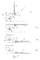
- the lifting / swiveling device 1 shown in FIG. 1 comprises a pair of lifting arms 2 arranged on the right and left under the rear of the vehicle, which on the one hand are articulated on the chassis 3 of the vehicle 4 and on the other hand carry the tail lift 5.
- the lifting arms 2 are pivotally mounted on the vehicle chassis 3 about a lying Hubarmschwenkachse 6, which extends transversely to the longitudinal direction of the lifting arms 2 and in the illustrated embodiment, in which the tail lift 5 is arranged at the rear of the vehicle, transverse to the direction of travel of the vehicle. 4 is aligned.
- tail lift 5 is pivotable relative to the lift arms 2 about a tailgate pivot axis 7, which extends parallel to the Hubarmschwenkachse 6.
- the Hubarmschwenkachse 6 and the liftgate pivot axis 7 are associated with two separate rotary motors 8 and 9, which advantageously in the Hubarmschwenkachse 6 defining Hubarmschwenklager 10 and the tail lift pivot axis 7 defining tail lift pivot bearings 11 are integrated, advantageously, these two pivot bearings 10 and 11 form.
- the two rotary motors 8 and 9 are independently controllable, so that in principle the tailgate can be pivoted independently of the position or movement of the lifting arms 2.
- a controller may be provided which determines a tail lift wall pivoting function of the position or movement of the lifting arms 2, in particular to pivot when lowering the lifting arms 2, the tail lift 5 relative to the lift arms 2 that independent of the optionally inclined vehicle position horizontal guide Tail lift 5 is possible.
- the illustrations (b), (c) and (d) of FIG. 1 show this.
- the second rotary motor 9 can be used in particular to zuzuschwenken the folded tailgate 5 before lifting the lifting arms 2 so far on the lifting arms 2 that when Nachobenschwenken the lifting arms 2, the folded tail lift 5 under the vehicle floor 13th moves.
- the folded tail lift 5 can be folded down after lifting the lifting arms 2 in opposite directions to the pivoting movement of the lifting arms 2 to the lifting arms 2, as shown in the representation (a) in Figure 3. Comparing FIGS. 2 (a) and 3 (a), it can be seen that, by the second rotary motor 9, the tail lift 5 is over a range of more than 270 ° with respect to the lift arms 2 can be pivoted. This is difficult to achieve with a conventional handlebar and swivel lever coupling.
- the two rotary motors 8 and 9 are advantageously, as shown in Figure 4, each hydraulic rotary motors with a motor shaft 14 which is received in a cylindrical shell-shaped housing 15 and on both end sides of said housing 15 emerges from this.
- On the motor shaft 14 sit two formed as a piston drive pieces 16 which are each in engagement with a threaded portion 17 of the motor shaft 14.
- the threaded portions 17 of the motor shaft 14 are designed in opposite directions as left and right-hand thread, so that the two drive pieces 16 operate in opposite directions.
- the piston forming drive pieces 16 are rotatably guided in the housing 15 axially displaceable, for example via spline / hub profile sections 18.
- the piston forming drive pieces 16 are sealed relative to the housing 15 so that pressure chambers 19, 20 and 21 formed on both sides of each piston are, wherein between the two pistons, a common pressure chamber 20 is provided.
- the housing 15 of the first rotary motor 8 is fastened in a torque-proof manner directly to the vehicle chassis 3.
- the tail lift 5 is fixed against rotation.
- the housing closing the front end bearing cap which can be rotatably connected to the tubular housing 15, in particular screwed or welded, via an articulation lever cause the rotationally fixed connection.
- the motor shafts may be mounted on the bearing caps, so that a direct introduction of force from the motor shaft 14 and thus low bending moments can be achieved on the housing 15.
- a particular advantage of the hydraulic rotary motors is their compact, in particular flat design.
- the lift arm-side articulation point of the tail lift can be brought particularly low over the floor and thus the tail lift can be set onto the floor with a minimal angle of inclination. This is almost impossible in conventional hoists, since the pivoting linkage to be articulated to the tailgate is there with respect to the tailgate pivot axis must have sufficient leverage, which inevitably requires a greater height of Hubarm procedureen tailgate point above the ground.
- the projecting out of the housing 15 stub of the motor shaft 14 carry the two lifting arms 2, which are of course fixed against rotation on the motor shaft 14.
- the other ends of the lifting arms 2 are connected to the also emerging from the housing 15 stub of the motor shaft 14 of the second rotary motor 9.
- a pressurized fluid supply 22 is seated at the axial end of the motor shaft 14 of the first rotary motor 8.
- the pressure fluid channels 23 and 24 in the motor shaft 14 of the first rotary motor 8 are applied with hydraulic oil to move the piston in the desired manner back and forth.
- This pressure fluid supply of the second rotary motor 9 via the lifting arms 2 avoids hydraulic hoses and allows the assembly of the lifting / pivoting device with only one pressure supply connection.
- the central pressurized fluid supply 22 may be in fluid communication with the motor shaft 14 of the first rotary motor 8 directly. Optionally, it can also be connected by means of a hydraulic rotary feedthrough.
- FIG. 5 shows the screw connection of the motor shaft 14 of the first rotary motor 8 with the lifting arm 2 with simultaneously sealing connection of the pressure oil supply.
- the channels can optionally also serve for control purposes or for adjusting the Faltladboard.
- FIG. 6 shows an alternative embodiment of the rotary motor 8 or of the rotary motor 9, in which the pressure is supplied to the pressure chambers 19, 20 and 21 via the housing 15.
- FIG. 7 shows both options, namely that the pressure chambers 19, 20 and 21 can take place both via the housing 14 and via the motor shaft 14 and the lifting arms 2 connected thereto.
- the piston outer guides on the housing 15 advantageously also to achieve larger rotational angle or torques also as a thread toothing, in particular helical splines 27, are executed, as shown in FIG shows.
- the threaded engagement between the drive pieces 16 and the housing 15 may be provided additionally or alternatively to the threaded engagement with the motor shaft 14.
- the latter can optionally be replaced by a rotationally fixed axial guide, for example by a splined shaft / hub connection, so that the drive pieces are guided only axially displaceably, but non-rotatably on the motor shaft 14.
- the threaded engagement may be provided on the piston outer guide in addition to the threaded engagement on the motor shaft 14 in order to achieve larger rotational angles or torques.
- ball or roller-like smooth running guides may be provided.
- the rotary motors 8 and 9 can also be designed as a double-piston motor, as shown in FIGS. 8 and 9.
- the motor shaft 14 unlike the previously described embodiments, not only a pair of drive pieces 16 are seated, but rather two pairs of each oppositely formed drive pieces 16, which are in threaded engagement with counter-threaded sections 17 of the motor shaft 14 respectively. If the pressure chambers 19, 21 and 29 are acted upon by the pressure P1, the opposing piston pairs go together, as Figure 8 shows. If, on the other hand, the pressure chambers 20 and 28 are subjected to the pressure P2, the drive pieces 16 designed as pistons move apart, as shown in FIG. 9, so that the respective rotational movements of the motor shaft 14 are established.
- the pressure chambers 19, 20, 21, 28 and 29 are fed via the housing 15.
- a pressurized fluid supply via the motor shaft 14 can also be provided here, as previously described.
- FIG. 10 An alternative embodiment of the lifting / swiveling device 1 is shown in FIG. 10.
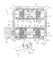
- this embodiment basically corresponds to the previously described according to FIGS. 1 to 3, but the second rotary motor 9 is seated for the pivotal movement of the tail lift 5 relative to the lift arms 2 not at the hinge point between the lift arms 2 and the tail lift 5. Rather, the second rotary motor 9 is combined with the first rotary motor 8 to a common motor unit, as shown in Figures 11 and 12.
- This combined motor unit comprises two coaxially arranged motor shafts 14 (a) and 14 (b), one of which is rotatably connected to the lifting arms 2 and the other drives a crank 30 which is coupled via a link 31 to the tailboard 5 to to swing them with respect to the lifting arms 2 (see Figure 10).
- the motor shaft 14 (a) of the first rotary motor 8, which is non-rotatably connected to the lift arms 2, is formed as a hollow shaft, so that the motor shaft 14 (b) of the second rotary motor 9 is rotated by the motor shaft 14 (A) of the first rotary motor 8 can extend therethrough. It protrudes axially from the end faces of the motor shaft 14 (a) and is there with the crank 30 against rotation and over this connected to the handlebar 31.
- the second rotary motor 9 is arranged, so to speak, in the first rotary motor 8.
- the two rotary motors 8 and 9 in this case have a common housing 15 in which the pistons formed by the respective drive pieces 16 are guided in the manner described above and received in a fluid-tight manner in order to form the corresponding pressure chambers.
- the two cranks 30 on the right and left of the motor shaft 14 (b) are synchronized by the latter. This is no longer the case with the two lifting arms 2, since the motor shaft 14 (a) of the first rotary motor 8 is no longer continuous.
- the synchronization of the lifting arms 2 and the split motor shaft 14, however, can be made via a torsion tube.
- the embodiment according to FIG. 13 provides that the rotary motor 8 does not have a circular cross-section but a flattened, in particular oval or on the installation conditions adapted cross section has. Both the housing 15 and the piston guided therein, which are formed by the drive pieces 16, are formed oval in cross section.
- the achievable thereby compact design is very important to realize flat drainage angle of a dropped on the floor tail lift.
- the torque on the piston can be effectively taken over the oval shape at the same time, so that, if necessary, can be dispensed with a rotationally fixed longitudinal guide, for example in the form of a splined / hub connection.
- Figures 13 and 14 show that the motor shaft 14 may be formed as a twisted polygonal or splined shaft, whereby an economical production can be achieved.
- the drive pieces 16 forming the piston can be sealed directly on the wave profile (see FIG.
Landscapes
- Engineering & Computer Science (AREA)
- Mechanical Engineering (AREA)
- Transportation (AREA)
- Physics & Mathematics (AREA)
- Fluid Mechanics (AREA)
- General Engineering & Computer Science (AREA)
- Power-Operated Mechanisms For Wings (AREA)
Priority Applications (1)
| Application Number | Priority Date | Filing Date | Title |
|---|---|---|---|
| EP06015377A EP1884402A1 (fr) | 2006-07-24 | 2006-07-24 | Dispositif de levage et de pivotement pour hayon élévateur ou rampe de chargement |
Applications Claiming Priority (1)
| Application Number | Priority Date | Filing Date | Title |
|---|---|---|---|
| EP06015377A EP1884402A1 (fr) | 2006-07-24 | 2006-07-24 | Dispositif de levage et de pivotement pour hayon élévateur ou rampe de chargement |
Publications (1)
| Publication Number | Publication Date |
|---|---|
| EP1884402A1 true EP1884402A1 (fr) | 2008-02-06 |
Family
ID=37459363
Family Applications (1)
| Application Number | Title | Priority Date | Filing Date |
|---|---|---|---|
| EP06015377A Withdrawn EP1884402A1 (fr) | 2006-07-24 | 2006-07-24 | Dispositif de levage et de pivotement pour hayon élévateur ou rampe de chargement |
Country Status (1)
| Country | Link |
|---|---|
| EP (1) | EP1884402A1 (fr) |
Cited By (3)
| Publication number | Priority date | Publication date | Assignee | Title |
|---|---|---|---|---|
| CN103953675A (zh) * | 2014-04-04 | 2014-07-30 | 广东机电职业技术学院 | 双活塞螺杆阻尼器 |
| DE102020001586A1 (de) | 2020-03-11 | 2021-09-16 | Walter Runkel | Schwenkantrieb für eine schwenkbare Rampe, insbesondere für die Ein- und Ausfahrhilfe für Rollstuhlfahrer |
| CN114515435A (zh) * | 2020-11-20 | 2022-05-20 | 乐森机器人(深圳)有限公司 | 一种车厢升降机构 |
Citations (8)
| Publication number | Priority date | Publication date | Assignee | Title |
|---|---|---|---|---|
| US3104593A (en) * | 1960-12-28 | 1963-09-24 | Regent Jack Mfg Co Inc | Fluid actuators |
| DE7337787U (de) * | 1973-10-20 | 1974-04-04 | Koepf E Fahrzeugbau Kg | Viehtransportwagen mit einem als Rampe verwendbaren LaderaumwandteiL |
| GB2006877A (en) * | 1977-10-26 | 1979-05-10 | Epitoegepgyarto Vallalat | Ram Cylinder |
| US5026248A (en) * | 1989-03-17 | 1991-06-25 | Logging Development Corporation | Hydrodynamic swing damper and tree handling vehicle incorporating the same |
| EP0713012A2 (fr) * | 1994-11-19 | 1996-05-22 | CKD Corporation | Actionneur rotatif |
| EP1369299A1 (fr) * | 2002-06-05 | 2003-12-10 | Gerd Bär | Hayon élévateur avec plate-forme assiste par un ressort |
| DE10245457B3 (de) * | 2002-09-27 | 2004-03-11 | Sachsenring Fahrzeugtechnik Gmbh | Schwenkmotor |
| EP1541412A1 (fr) * | 2003-12-09 | 2005-06-15 | Sörensen Hydraulik Zweigniederlassung, Ulfborg, Filial af Sörensen Hydraulik GmbH, Tyskland | Système de hayon élévateur |
-
2006
- 2006-07-24 EP EP06015377A patent/EP1884402A1/fr not_active Withdrawn
Patent Citations (8)
| Publication number | Priority date | Publication date | Assignee | Title |
|---|---|---|---|---|
| US3104593A (en) * | 1960-12-28 | 1963-09-24 | Regent Jack Mfg Co Inc | Fluid actuators |
| DE7337787U (de) * | 1973-10-20 | 1974-04-04 | Koepf E Fahrzeugbau Kg | Viehtransportwagen mit einem als Rampe verwendbaren LaderaumwandteiL |
| GB2006877A (en) * | 1977-10-26 | 1979-05-10 | Epitoegepgyarto Vallalat | Ram Cylinder |
| US5026248A (en) * | 1989-03-17 | 1991-06-25 | Logging Development Corporation | Hydrodynamic swing damper and tree handling vehicle incorporating the same |
| EP0713012A2 (fr) * | 1994-11-19 | 1996-05-22 | CKD Corporation | Actionneur rotatif |
| EP1369299A1 (fr) * | 2002-06-05 | 2003-12-10 | Gerd Bär | Hayon élévateur avec plate-forme assiste par un ressort |
| DE10245457B3 (de) * | 2002-09-27 | 2004-03-11 | Sachsenring Fahrzeugtechnik Gmbh | Schwenkmotor |
| EP1541412A1 (fr) * | 2003-12-09 | 2005-06-15 | Sörensen Hydraulik Zweigniederlassung, Ulfborg, Filial af Sörensen Hydraulik GmbH, Tyskland | Système de hayon élévateur |
Cited By (4)
| Publication number | Priority date | Publication date | Assignee | Title |
|---|---|---|---|---|
| CN103953675A (zh) * | 2014-04-04 | 2014-07-30 | 广东机电职业技术学院 | 双活塞螺杆阻尼器 |
| DE102020001586A1 (de) | 2020-03-11 | 2021-09-16 | Walter Runkel | Schwenkantrieb für eine schwenkbare Rampe, insbesondere für die Ein- und Ausfahrhilfe für Rollstuhlfahrer |
| DE102020001586B4 (de) | 2020-03-11 | 2022-08-11 | Walter Runkel | Schwenkantrieb für eine schwenkbare Rampe, insbesondere für die Ein- und Ausfahrhilfe für Rollstuhlfahrer |
| CN114515435A (zh) * | 2020-11-20 | 2022-05-20 | 乐森机器人(深圳)有限公司 | 一种车厢升降机构 |
Similar Documents
| Publication | Publication Date | Title |
|---|---|---|
| EP0279237B2 (fr) | Dispositif d'actionnement rotatif pour manoeuvrer un battant de porte pivotant, en particulier de véhicule | |
| EP1098423A1 (fr) | Entraínement pour meubles par moteur électrique | |
| EP1920958A1 (fr) | Dispositif de transfert d'une paroi d'un récipient de transport entre une position fermée et une position ouverte et récipient de transport avec un tel dispositif | |
| DE2633578A1 (de) | Vibrator mit veraenderbarer fliehkraft fuer bodenverdichtungswalzen | |
| EP2799283B1 (fr) | Véhicule de transport de charge doté d'un conteneur interchangeable et d'un appareil de levage pour un conteneur interchangeable | |
| DE10048224A1 (de) | Verriegelungseinheit für einen Teleskopausleger eines Krans | |
| DE69606799T2 (de) | Vorrichtung zum Entleeren eines Müllbehälters in den Sammelbehälter eines Müllfahrzeuges | |
| DE102005005237B3 (de) | Anordnung zum Schwenken der Teile eines Fahrzeugverdecks | |
| DE602004000462T2 (de) | Stellantrieb mit zwei Betriebsarten | |
| EP2061677A1 (fr) | Hayon elevateur | |
| DE202005011280U1 (de) | Hub-/Schwenkvorrichtung für Ladebordwände und/oder -rampen | |
| EP1884402A1 (fr) | Dispositif de levage et de pivotement pour hayon élévateur ou rampe de chargement | |
| EP1825082B1 (fr) | Dispositif de stationnement pour véhicules automobiles | |
| DE2834498A1 (de) | Garage zum abstellen von fahrzeugen uebereinander | |
| EP1702792B1 (fr) | Système de levage de benne amovible de camion | |
| DE19539043A1 (de) | Hydrostatisch angetriebenes Fahrzeug | |
| DE3323428C2 (fr) | ||
| EP1140583B1 (fr) | Dispositif d'essuie-glace pour vehicules et procede d'utilisation d'une tringlerie de bras d'essuie-glace | |
| EP1467900B1 (fr) | Systeme d'entrainement pour un essuie-glace de vehicule pivotant | |
| DE4136907C2 (fr) | ||
| AT408735B (de) | Betätigungsanordnung für schwenkbare teile an fahrzeugen | |
| EP0698575B1 (fr) | Elévateur, en particulier pour véhicules automobiles | |
| EP3153629B1 (fr) | Entraînement pivotant hydraulique et dispositif de préhension comprenant un tel entraînement pivotant | |
| DE10036922C1 (de) | Hauptlagereinheit für ein Cabrio-Verdeck | |
| DE102009000542B4 (de) | Antrieb für einen Flügel einer Tür |
Legal Events
| Date | Code | Title | Description |
|---|---|---|---|
| PUAI | Public reference made under article 153(3) epc to a published international application that has entered the european phase |
Free format text: ORIGINAL CODE: 0009012 |
|
| AK | Designated contracting states |
Kind code of ref document: A1 Designated state(s): AT BE BG CH CY CZ DE DK EE ES FI FR GB GR HU IE IS IT LI LT LU LV MC NL PL PT RO SE SI SK TR |
|
| AX | Request for extension of the european patent |
Extension state: AL BA HR MK YU |
|
| 17P | Request for examination filed |
Effective date: 20080611 |
|
| AKX | Designation fees paid |
Designated state(s): AT BE BG CH CY CZ DE DK EE ES FI FR GB GR HU IE IS IT LI LT LU LV MC NL PL PT RO SE SI SK TR |
|
| STAA | Information on the status of an ep patent application or granted ep patent |
Free format text: STATUS: THE APPLICATION IS DEEMED TO BE WITHDRAWN |
|
| 18D | Application deemed to be withdrawn |
Effective date: 20100202 |