EP1884458A2 - Structure de châssis et véhicule routier doté d'une telle structure de châssis - Google Patents
Structure de châssis et véhicule routier doté d'une telle structure de châssis Download PDFInfo
- Publication number
- EP1884458A2 EP1884458A2 EP07110181A EP07110181A EP1884458A2 EP 1884458 A2 EP1884458 A2 EP 1884458A2 EP 07110181 A EP07110181 A EP 07110181A EP 07110181 A EP07110181 A EP 07110181A EP 1884458 A2 EP1884458 A2 EP 1884458A2
- Authority
- EP
- European Patent Office
- Prior art keywords
- frame
- suspension
- construction
- suspended
- fork head
- Prior art date
- Legal status (The legal status is an assumption and is not a legal conclusion. Google has not performed a legal analysis and makes no representation as to the accuracy of the status listed.)
- Withdrawn
Links
Images


Classifications
-
- B—PERFORMING OPERATIONS; TRANSPORTING
- B62—LAND VEHICLES FOR TRAVELLING OTHERWISE THAN ON RAILS
- B62K—CYCLES; CYCLE FRAMES; CYCLE STEERING DEVICES; RIDER-OPERATED TERMINAL CONTROLS SPECIALLY ADAPTED FOR CYCLES; CYCLE AXLE SUSPENSIONS; CYCLE SIDECARS, FORECARS, OR THE LIKE
- B62K5/00—Cycles with handlebars, equipped with three or more main road wheels
- B62K5/01—Motorcycles with four or more wheels
-
- B—PERFORMING OPERATIONS; TRANSPORTING
- B62—LAND VEHICLES FOR TRAVELLING OTHERWISE THAN ON RAILS
- B62K—CYCLES; CYCLE FRAMES; CYCLE STEERING DEVICES; RIDER-OPERATED TERMINAL CONTROLS SPECIALLY ADAPTED FOR CYCLES; CYCLE AXLE SUSPENSIONS; CYCLE SIDECARS, FORECARS, OR THE LIKE
- B62K13/00—Cycles convertible to, or transformable into, other types of cycles or land vehicle
- B62K13/06—Cycles convertible to, or transformable into, other types of cycles or land vehicle to a quadricycle, e.g. by coupling together two bicycles side by side
-
- Y—GENERAL TAGGING OF NEW TECHNOLOGICAL DEVELOPMENTS; GENERAL TAGGING OF CROSS-SECTIONAL TECHNOLOGIES SPANNING OVER SEVERAL SECTIONS OF THE IPC; TECHNICAL SUBJECTS COVERED BY FORMER USPC CROSS-REFERENCE ART COLLECTIONS [XRACs] AND DIGESTS
- Y10—TECHNICAL SUBJECTS COVERED BY FORMER USPC
- Y10S—TECHNICAL SUBJECTS COVERED BY FORMER USPC CROSS-REFERENCE ART COLLECTIONS [XRACs] AND DIGESTS
- Y10S180/00—Motor vehicles
- Y10S180/908—Motor vehicles with short wheelbase
Definitions
- the invention relates to a frame construction for a road vehicle, comprising a main frame, which on the front edge is provided with a fork head and with front suspension means and which on the rear edge is provided with rear suspension means, a front frame, which is rigidly connected to the main frame and which is suspended from the front suspension means, and a rear frame, which is suspended from the rear suspension means.
- Such a frame construction is known from Brazilian patent application 8.600.806 .
- the rear frame thereof is resiliently suspended in relation to the main frame.
- Such a construction possesses a high unsprung weight, which is not beneficial to the roadholding.
- a further frame construction is known from American patent specification 6.783.158 .
- a main frame is used which can be used both as a two-wheeled, as a three-wheeled and as a four-wheeled road vehicle.
- the front frame is in this case rigidly suspended from the main frame.
- the wheels are resiliently suspended from the front frame.
- the points of attachment of the front frame are located on the lowermost portion of the main frame.
- a same type of suspension appears in the realization of the two-wheeled, three-wheeled and four-wheeled embodiment.
- Such a frame construction is especially suitable for lighter vehicles.
- the object of the invention is to realize a frame construction of this type, comprising a main frame provided with a fork head, as known from Brazilian patent application 8.600.806 , such that this provides better roadholding and is also suitable for heavier vehicles.
- This object is achieved by the rear frame being rigidly suspended from the main frame.
- the rear frame has on either side resiliently supporting suspension constructions for the suspension of a respective wheel.
- the rear frame can comprise drive means for driving the associated wheels.
- the drive means can comprise a differential.
- the points of attachment of the front frame are located on the lowermost and uppermost portions of the main frame, which favourably influences the stiffness and stability of the frame construction.
- the rigid connection which is thus obtained between the front frame and the main frame results in a robust frame construction, which is suitable for heavier vehicles.
- the connection between the front frame and the fork head can be variously achieved, though according to a particularly efficient embodiment the front frame possesses for this purpose a freely projecting frame piece accommodated in the fork head.
- the rear frame too, can be rigidly suspended from the main frame. An altogether rigid and robust construction is thereby obtained, which provides particularly good riding characteristics.
- a main frame which possesses a flat base on which the rider can perch with his feet. Furthermore, in the main frame which is thus used, a more or less chair-like seat can be used, such that the rider can mount it in the same way as occurs with a scooter.
- a main frame is suitable for lighter applications, as has already been mentioned above. Since, however, the frame construction according to the invention relates to heavier vehicles, such a main frame would be less suitable.
- a main frame is hence used which is realized as a motorcycle frame.
- Such a motorcycle frame comprises a saddle bar which extends rearwards from the fork head. The rider must therefore sit astride such a motorcycle frame, on the saddle present on the saddle bar.
- Such a motorcycle frame comprises two front frame bars extending downwards from the fork head. To these two front frame bars and the fork head, the front frame can be connected. Furthermore, such a motorcycle frame possesses two rear frame bars extending downwards from the saddle bar, which means that the rear frame can be connected to both rear frame bars.
- the front frame can comprise on either side resiliently supporting suspension constructions for the suspension of a respective wheel, whilst the front frame can also comprise steering means for steering the wheels.
- the invention further relates to a road vehicle comprising a frame construction as described above.
- a road vehicle comprising a frame construction as described above.
- Such a road vehicle possesses wheels, which are suspended from the suspension constructions, and also steering means for steering the wheels suspended from the front frame, as well as a drive train for driving the wheels suspended from the rear frame.
- This drive train can comprise a drive source, such as an internal combustion engine, suspended from the main frame.
- the drive train comprises a chain or belt transmission as is usual in motorcycles, and a differential provided with a chain wheel or pulley.
- the invention further relates to a kit comprising a main frame, which on the front edge is provided with a fork head and with front suspension means and which on the rear edge is provided with rear suspension means, and a front frame provided with coupling means for the suspension thereof from the front suspension means and a frame piece which can be coupled to the fork head, as well as a rear frame provided with coupling means for the rigid suspension thereof from the rear suspension means.
- the front frame is likewise suspended from front suspension means of the main frame.
- suspension means which are standardly present on the main frame, for example suspension means used for the suspension of the power source, the pedals, protective bars and the like.
- the rear suspension means can be standardly present on the main frame.
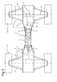
- the frame construction 1 represented in Figures 1 and 2 is made up of the motorcycle frame, denoted in its entirety by 2, the front frame, denoted in its entirety by 3, and the rear frame, denoted in its entirety by 4.
- the motorcycle frame 2, which in Figures 5 and 6 is represented separately, comprises a fork head 5 and a saddle bar 6 extending rearwards in relation to the fork head 5.
- Extending downwards in relation to the fork head 5 are the front frame bars 7, which, as can be seen in the top view of Figure 6, run directed away from one another in this direction.
- a transverse beam 8 Fastened to the lowermost end of these front frame bars 7 is a transverse beam 8, at the extremities of which the fastening means 9 are provided.
- From the saddle bar 6, the rear frame bars 10 run downwards away from one another.
- These rear frame bars 10 are mutually connected by means of the transverse beam 11.
- fastening means 12 are likewise provided.
- the front frame 3 is fastened to the fastening means 9.
- the front frame 3 further possesses a freely projecting frame piece 13, which is accommodated in the fork head 5.
- the front frame 3 is stiffly or rigidly fastened to the motorcycle frame 2.
- the rear frame 4 is stiffly fastened to the fastening means 12. An entirely stiff, rigid frame construction 1 is thereby obtained.
- suspension means 15 which are known per se. These suspension means 15 comprise pairs of bars 16, 17, lying one above the other, and spring /shock absorber devices 18 (represented diagrammatically).
- a steering device 19 and a drive train 20 are present.
- This drive train 20 comprises an internal combustion engine 22, which is coupled via a chain or belt transmission 23 to the differential 21.
- the differential 21 of the drive train 20 is represented.
- the differential 21 comprises a housing 24, in which a standardly realized production differential 25 is accommodated.
- Fastened to the outer side of the housing 24 is the pulley wheel or chain wheel 26, over which a pulley or chain (not shown) is guided.
- the two drive axles 27 are represented, which, via homokinetic couplings 28, are connected to the axle journals 29 mounted in the bearing housings 30.
- Fastened to the mutually facing ends of the axle journals 29, which emerge in the production differential 25, are the usual helical gears 31.
- the likewise helical auxiliary gears 32 are likewise suspended in freely rotating arrangement in the production differential. These gears 31, 32 are mutually engaged.
Landscapes
- Engineering & Computer Science (AREA)
- Mechanical Engineering (AREA)
- Automatic Cycles, And Cycles In General (AREA)
Applications Claiming Priority (1)
| Application Number | Priority Date | Filing Date | Title |
|---|---|---|---|
| NL2000101A NL2000101C2 (nl) | 2006-06-14 | 2006-06-14 | Frameconstructie, alsmede wegvoertuig voorzien van een dergelijke frameconstructie. |
Publications (2)
| Publication Number | Publication Date |
|---|---|
| EP1884458A2 true EP1884458A2 (fr) | 2008-02-06 |
| EP1884458A3 EP1884458A3 (fr) | 2010-06-02 |
Family
ID=37668200
Family Applications (1)
| Application Number | Title | Priority Date | Filing Date |
|---|---|---|---|
| EP07110181A Withdrawn EP1884458A3 (fr) | 2006-06-14 | 2007-06-13 | Structure de châssis et véhicule routier doté d'une telle structure de châssis |
Country Status (3)
| Country | Link |
|---|---|
| US (1) | US7815008B2 (fr) |
| EP (1) | EP1884458A3 (fr) |
| NL (1) | NL2000101C2 (fr) |
Families Citing this family (6)
| Publication number | Priority date | Publication date | Assignee | Title |
|---|---|---|---|---|
| WO2009042314A1 (fr) | 2007-09-27 | 2009-04-02 | American Axle & Manufacturing, Inc. | Ensemble d'essieu de motocycle |
| US7926607B2 (en) * | 2008-03-05 | 2011-04-19 | Paul Seiter | Three-wheel vehicle |
| JP5560101B2 (ja) * | 2010-05-31 | 2014-07-23 | 本田技研工業株式会社 | 不整地走行車両 |
| JP5872147B2 (ja) * | 2010-09-21 | 2016-03-01 | 寛之 大橋 | 後輪ユニット、これを備える自動三輪車、及び自動二輪車を自動三輪車に改造する方法 |
| CN106080904B (zh) * | 2016-08-15 | 2019-03-01 | 郑策 | 一种摩托车车架 |
| CN107697203B (zh) * | 2017-10-20 | 2023-12-22 | 浙江联宜电机有限公司 | 代步车双弯双大梁结构 |
Citations (5)
| Publication number | Priority date | Publication date | Assignee | Title |
|---|---|---|---|---|
| BR8600806A (pt) | 1986-02-07 | 1987-09-08 | Motoplay Comercial Ltda | Aperfeicoamento em quadriciclo |
| US6250415B1 (en) * | 1999-02-17 | 2001-06-26 | Yamaha Hatsudoki Kabushiki Kaisha | Atv transmission |
| US6783158B2 (en) | 2000-09-21 | 2004-08-31 | Honda Giken Kogyo Kabushiki Kaisha | Vehicle |
| US20050034906A1 (en) * | 2003-08-12 | 2005-02-17 | Unique Product & Design Co., Ltd. | Power transmitting system for an electric car |
| EP1642814A2 (fr) * | 2004-09-30 | 2006-04-05 | HONDA MOTOR CO., Ltd. | Structure de cadre |
Family Cites Families (24)
| Publication number | Priority date | Publication date | Assignee | Title |
|---|---|---|---|---|
| AT178544B (de) * | 1953-02-03 | 1954-05-25 | Ottokar Stepanek | Aus einem Motorrad und einem zweirädrigen Fahrgestell bestehendes Kleinkraftfahrzeug |
| US3470768A (en) * | 1968-01-02 | 1969-10-07 | Carlisle Corp | Differential assembly |
| US3610358A (en) * | 1969-07-23 | 1971-10-05 | Walter H Korff | Cycle car |
| US3768336A (en) * | 1971-06-29 | 1973-10-30 | Illinois Tool Works | Differential |
| US3827705A (en) | 1972-12-11 | 1974-08-06 | R Templeton | Tricycle drive train |
| US4388842A (en) * | 1980-07-01 | 1983-06-21 | Kawasaki Motors Corp. | Locking device for a differential mechanism |
| US4650203A (en) * | 1983-04-21 | 1987-03-17 | Suzuki Motor Company Limited | Steering apparatus for a saddle riding type motorcar having four wheels |
| JPS6078829A (ja) * | 1983-10-06 | 1985-05-04 | Honda Motor Co Ltd | 車両における車輪駆動装置 |
| JPS60134087U (ja) * | 1984-02-20 | 1985-09-06 | 本田技研工業株式会社 | 自動四輪車の車体フレ−ム |
| JPS60213577A (ja) * | 1984-04-06 | 1985-10-25 | Suzuki Motor Co Ltd | 鞍乗型四輪車のフレ−ム構造 |
| US4770262A (en) * | 1984-08-31 | 1988-09-13 | Honda Giken Kogyo Kabushiki Kaisha | Four-wheel motor vehicle with riding saddle seat |
| JPH0686230B2 (ja) * | 1985-10-07 | 1994-11-02 | 本田技研工業株式会社 | 車両用フレ−ム |
| JPH01109186A (ja) * | 1987-10-22 | 1989-04-26 | Honda Motor Co Ltd | 車両用フレーム構造 |
| JPH01197190A (ja) * | 1988-02-03 | 1989-08-08 | Suzuki Motor Co Ltd | 鞍乗型車両のフレーム |
| JP2671346B2 (ja) * | 1988-02-12 | 1997-10-29 | スズキ株式会社 | 鞍乗型車両の車体フレーム構造 |
| US5236060A (en) * | 1992-04-22 | 1993-08-17 | Huber William D | Three-wheel vehicle and conversion kit |
| DE9409735U1 (de) | 1994-06-20 | 1995-07-20 | Bielefelder Küchenmaschinen- und Transportgerätefabrik vom Braucke GmbH, 33739 Bielefeld | Zweirädrige Steckkarre mit Vertikalrahmen und Schüppe als Lastaufnahmemittel |
| CA2202330A1 (fr) * | 1997-04-10 | 1998-10-10 | Bombardier Inc. | Vehicule tout terrain |
| JP3792851B2 (ja) * | 1997-08-27 | 2006-07-05 | 本田技研工業株式会社 | 鞍乗り型車両のフレーム構造 |
| JP3869122B2 (ja) * | 1998-07-16 | 2007-01-17 | 本田技研工業株式会社 | 4輪バギー車の車体フレーム構造 |
| US6799781B2 (en) * | 2000-03-13 | 2004-10-05 | Bombardier Recreational Products Inc. | Frames for all-terrain vehicles |
| JP2003011874A (ja) * | 2001-06-29 | 2003-01-15 | Suzuki Motor Corp | 鞍乗型不整地走行車両の車体フレームおよびその製造方法 |
| JP2004314939A (ja) * | 2003-04-04 | 2004-11-11 | Honda Motor Co Ltd | 鞍乗り型車両のフレーム構造およびフレーム製造方法 |
| JP2006096164A (ja) * | 2004-09-29 | 2006-04-13 | Honda Motor Co Ltd | 鞍乗型車両の車体フレーム |
-
2006
- 2006-06-14 NL NL2000101A patent/NL2000101C2/nl not_active IP Right Cessation
-
2007
- 2007-06-13 EP EP07110181A patent/EP1884458A3/fr not_active Withdrawn
- 2007-06-13 US US11/818,096 patent/US7815008B2/en active Active
Patent Citations (5)
| Publication number | Priority date | Publication date | Assignee | Title |
|---|---|---|---|---|
| BR8600806A (pt) | 1986-02-07 | 1987-09-08 | Motoplay Comercial Ltda | Aperfeicoamento em quadriciclo |
| US6250415B1 (en) * | 1999-02-17 | 2001-06-26 | Yamaha Hatsudoki Kabushiki Kaisha | Atv transmission |
| US6783158B2 (en) | 2000-09-21 | 2004-08-31 | Honda Giken Kogyo Kabushiki Kaisha | Vehicle |
| US20050034906A1 (en) * | 2003-08-12 | 2005-02-17 | Unique Product & Design Co., Ltd. | Power transmitting system for an electric car |
| EP1642814A2 (fr) * | 2004-09-30 | 2006-04-05 | HONDA MOTOR CO., Ltd. | Structure de cadre |
Also Published As
| Publication number | Publication date |
|---|---|
| US7815008B2 (en) | 2010-10-19 |
| NL2000101C2 (nl) | 2007-12-17 |
| US20070296196A1 (en) | 2007-12-27 |
| EP1884458A3 (fr) | 2010-06-02 |
Similar Documents
| Publication | Publication Date | Title |
|---|---|---|
| US10843758B2 (en) | Vehicle having a suspension assembly including a swing arm | |
| US8061465B2 (en) | Three-wheeled vehicle with centrally positioned motor and driver's seat | |
| US20090224497A1 (en) | Three-wheel vehicle | |
| EP1403171A1 (fr) | Véhicule à trois roues avec dispositif oscillant | |
| US7815008B2 (en) | Frame construction and road vehicle provided with such a frame construction | |
| PL362951A1 (en) | Front drive with steered front wheel | |
| NZ203181A (en) | Four wheeled motorcycle | |
| EP2969726A2 (fr) | Suspension arrière de bicyclette | |
| US8662514B2 (en) | Multi-person tricycle | |
| US11034409B2 (en) | Suspension assembly for a vehicle | |
| CN108698498B (zh) | 三轮跨骑座椅式车辆族系 | |
| US20100320023A1 (en) | Four wheel vehicle having a rotatable body section and method therefor | |
| JP2011126514A (ja) | 前二輪式三輪車 | |
| US20240367750A1 (en) | Bicycle Rear Suspension | |
| JPH05213253A (ja) | 後二輪用電動車両 | |
| US20100013180A1 (en) | Three-wheeled vehicle with rear axle control link | |
| CN205087108U (zh) | 无辐条自行车 | |
| JP2621273B2 (ja) | 鞍乗型車両の燃料タンク取付構造 | |
| US7556275B2 (en) | Saddle type vehicle | |
| US8733491B2 (en) | Method and apparatus for an offroad vehicle | |
| CN2252760Y (zh) | 一种非传统结构的高性能自行车 | |
| CN203246555U (zh) | 三轮摩托车或电动三轮车的新型前减震装置 | |
| CN116323379A (zh) | 对摩托车系列中的摩托车进行组装的方法及对应的摩托车 | |
| JPS61181789A (ja) | 車輌用vベルト伝動式操向前一輪動力伝達装置 | |
| JP2001018874A (ja) | 四輪自転車 |
Legal Events
| Date | Code | Title | Description |
|---|---|---|---|
| PUAI | Public reference made under article 153(3) epc to a published international application that has entered the european phase |
Free format text: ORIGINAL CODE: 0009012 |
|
| AK | Designated contracting states |
Kind code of ref document: A2 Designated state(s): AT BE BG CH CY CZ DE DK EE ES FI FR GB GR HU IE IS IT LI LT LU LV MC MT NL PL PT RO SE SI SK TR |
|
| AX | Request for extension of the european patent |
Extension state: AL BA HR MK YU |
|
| PUAL | Search report despatched |
Free format text: ORIGINAL CODE: 0009013 |
|
| AK | Designated contracting states |
Kind code of ref document: A3 Designated state(s): AT BE BG CH CY CZ DE DK EE ES FI FR GB GR HU IE IS IT LI LT LU LV MC MT NL PL PT RO SE SI SK TR |
|
| AX | Request for extension of the european patent |
Extension state: AL BA HR MK RS |
|
| RIC1 | Information provided on ipc code assigned before grant |
Ipc: B62K 13/06 20060101ALI20100429BHEP Ipc: B62K 5/00 20060101ALI20100429BHEP Ipc: B62K 11/02 20060101ALI20100429BHEP Ipc: B62K 13/08 20060101AFI20080102BHEP |
|
| 17P | Request for examination filed |
Effective date: 20101201 |
|
| 17Q | First examination report despatched |
Effective date: 20110111 |
|
| AKX | Designation fees paid |
Designated state(s): AT BE BG CH CY CZ DE DK EE ES FI FR GB GR HU IE IS IT LI LT LU LV MC MT NL PL PT RO SE SI SK TR |
|
| STAA | Information on the status of an ep patent application or granted ep patent |
Free format text: STATUS: THE APPLICATION IS DEEMED TO BE WITHDRAWN |
|
| 18D | Application deemed to be withdrawn |
Effective date: 20110524 |