EP1884651A1 - Ölabscheider für gasbetriebene Brennkraftmaschinen - Google Patents
Ölabscheider für gasbetriebene Brennkraftmaschinen Download PDFInfo
- Publication number
- EP1884651A1 EP1884651A1 EP06015968A EP06015968A EP1884651A1 EP 1884651 A1 EP1884651 A1 EP 1884651A1 EP 06015968 A EP06015968 A EP 06015968A EP 06015968 A EP06015968 A EP 06015968A EP 1884651 A1 EP1884651 A1 EP 1884651A1
- Authority
- EP
- European Patent Office
- Prior art keywords
- oil
- gas
- internal combustion
- fuel
- oil separator
- Prior art date
- Legal status (The legal status is an assumption and is not a legal conclusion. Google has not performed a legal analysis and makes no representation as to the accuracy of the status listed.)
- Granted
Links
- 238000002485 combustion reaction Methods 0.000 title claims description 22
- 239000000446 fuel Substances 0.000 claims abstract description 89
- 230000005484 gravity Effects 0.000 claims abstract description 18
- 238000000926 separation method Methods 0.000 claims abstract description 6
- 239000003638 chemical reducing agent Substances 0.000 claims description 16
- 238000010276 construction Methods 0.000 claims description 4
- 239000003921 oil Substances 0.000 description 82
- 239000007789 gas Substances 0.000 description 76
- VNWKTOKETHGBQD-UHFFFAOYSA-N methane Chemical compound C VNWKTOKETHGBQD-UHFFFAOYSA-N 0.000 description 8
- 239000000443 aerosol Substances 0.000 description 5
- 239000007788 liquid Substances 0.000 description 5
- 238000002347 injection Methods 0.000 description 3
- 239000007924 injection Substances 0.000 description 3
- 239000003345 natural gas Substances 0.000 description 3
- ATUOYWHBWRKTHZ-UHFFFAOYSA-N Propane Chemical compound CCC ATUOYWHBWRKTHZ-UHFFFAOYSA-N 0.000 description 2
- 238000001914 filtration Methods 0.000 description 2
- 239000003915 liquefied petroleum gas Substances 0.000 description 2
- 239000010687 lubricating oil Substances 0.000 description 2
- 239000003305 oil spill Substances 0.000 description 2
- 238000011144 upstream manufacturing Methods 0.000 description 2
- 239000001273 butane Substances 0.000 description 1
- 239000006227 byproduct Substances 0.000 description 1
- 239000003054 catalyst Substances 0.000 description 1
- 238000011109 contamination Methods 0.000 description 1
- 230000000694 effects Effects 0.000 description 1
- 238000005516 engineering process Methods 0.000 description 1
- 239000000295 fuel oil Substances 0.000 description 1
- 238000005984 hydrogenation reaction Methods 0.000 description 1
- 238000012423 maintenance Methods 0.000 description 1
- 238000004519 manufacturing process Methods 0.000 description 1
- IJDNQMDRQITEOD-UHFFFAOYSA-N n-butane Chemical compound CCCC IJDNQMDRQITEOD-UHFFFAOYSA-N 0.000 description 1
- OFBQJSOFQDEBGM-UHFFFAOYSA-N n-pentane Natural products CCCCC OFBQJSOFQDEBGM-UHFFFAOYSA-N 0.000 description 1
- 239000002343 natural gas well Substances 0.000 description 1
- 239000003208 petroleum Substances 0.000 description 1
- 238000005504 petroleum refining Methods 0.000 description 1
- 239000001294 propane Substances 0.000 description 1
- VMXUWOKSQNHOCA-UKTHLTGXSA-N ranitidine Chemical compound [O-][N+](=O)\C=C(/NC)NCCSCC1=CC=C(CN(C)C)O1 VMXUWOKSQNHOCA-UKTHLTGXSA-N 0.000 description 1
- 229920006395 saturated elastomer Polymers 0.000 description 1
- 238000007789 sealing Methods 0.000 description 1
- 239000010913 used oil Substances 0.000 description 1
Images
Classifications
-
- B—PERFORMING OPERATIONS; TRANSPORTING
- B01—PHYSICAL OR CHEMICAL PROCESSES OR APPARATUS IN GENERAL
- B01D—SEPARATION
- B01D46/00—Filters or filtering processes specially modified for separating dispersed particles from gases or vapours
- B01D46/24—Particle separators, e.g. dust precipitators, using rigid hollow filter bodies
- B01D46/2403—Particle separators, e.g. dust precipitators, using rigid hollow filter bodies characterised by the physical shape or structure of the filtering element
-
- F—MECHANICAL ENGINEERING; LIGHTING; HEATING; WEAPONS; BLASTING
- F01—MACHINES OR ENGINES IN GENERAL; ENGINE PLANTS IN GENERAL; STEAM ENGINES
- F01M—LUBRICATING OF MACHINES OR ENGINES IN GENERAL; LUBRICATING INTERNAL COMBUSTION ENGINES; CRANKCASE VENTILATING
- F01M11/00—Component parts, details or accessories, not provided for in, or of interest apart from, groups F01M1/00 - F01M9/00
- F01M11/08—Separating lubricant from air or fuel-air mixture before entry into cylinder
-
- B—PERFORMING OPERATIONS; TRANSPORTING
- B01—PHYSICAL OR CHEMICAL PROCESSES OR APPARATUS IN GENERAL
- B01D—SEPARATION
- B01D45/00—Separating dispersed particles from gases or vapours by gravity, inertia, or centrifugal forces
- B01D45/02—Separating dispersed particles from gases or vapours by gravity, inertia, or centrifugal forces by utilising gravity
-
- B—PERFORMING OPERATIONS; TRANSPORTING
- B01—PHYSICAL OR CHEMICAL PROCESSES OR APPARATUS IN GENERAL
- B01D—SEPARATION
- B01D46/00—Filters or filtering processes specially modified for separating dispersed particles from gases or vapours
- B01D46/0027—Filters or filtering processes specially modified for separating dispersed particles from gases or vapours with additional separating or treating functions
- B01D46/003—Filters or filtering processes specially modified for separating dispersed particles from gases or vapours with additional separating or treating functions including coalescing means for the separation of liquid
- B01D46/0031—Filters or filtering processes specially modified for separating dispersed particles from gases or vapours with additional separating or treating functions including coalescing means for the separation of liquid with collecting, draining means
-
- B—PERFORMING OPERATIONS; TRANSPORTING
- B01—PHYSICAL OR CHEMICAL PROCESSES OR APPARATUS IN GENERAL
- B01D—SEPARATION
- B01D50/00—Combinations of methods or devices for separating particles from gases or vapours
- B01D50/20—Combinations of devices covered by groups B01D45/00 and B01D46/00
-
- F—MECHANICAL ENGINEERING; LIGHTING; HEATING; WEAPONS; BLASTING
- F01—MACHINES OR ENGINES IN GENERAL; ENGINE PLANTS IN GENERAL; STEAM ENGINES
- F01M—LUBRICATING OF MACHINES OR ENGINES IN GENERAL; LUBRICATING INTERNAL COMBUSTION ENGINES; CRANKCASE VENTILATING
- F01M11/00—Component parts, details or accessories, not provided for in, or of interest apart from, groups F01M1/00 - F01M9/00
- F01M11/03—Mounting or connecting of lubricant purifying means relative to the machine or engine; Details of lubricant purifying means
-
- F—MECHANICAL ENGINEERING; LIGHTING; HEATING; WEAPONS; BLASTING
- F02—COMBUSTION ENGINES; HOT-GAS OR COMBUSTION-PRODUCT ENGINE PLANTS
- F02M—SUPPLYING COMBUSTION ENGINES IN GENERAL WITH COMBUSTIBLE MIXTURES OR CONSTITUENTS THEREOF
- F02M21/00—Apparatus for supplying engines with non-liquid fuels, e.g. gaseous fuels stored in liquid form
- F02M21/02—Apparatus for supplying engines with non-liquid fuels, e.g. gaseous fuels stored in liquid form for gaseous fuels
-
- F—MECHANICAL ENGINEERING; LIGHTING; HEATING; WEAPONS; BLASTING
- F02—COMBUSTION ENGINES; HOT-GAS OR COMBUSTION-PRODUCT ENGINE PLANTS
- F02M—SUPPLYING COMBUSTION ENGINES IN GENERAL WITH COMBUSTIBLE MIXTURES OR CONSTITUENTS THEREOF
- F02M21/00—Apparatus for supplying engines with non-liquid fuels, e.g. gaseous fuels stored in liquid form
- F02M21/02—Apparatus for supplying engines with non-liquid fuels, e.g. gaseous fuels stored in liquid form for gaseous fuels
- F02M21/0218—Details on the gaseous fuel supply system, e.g. tanks, valves, pipes, pumps, rails, injectors or mixers
- F02M21/0227—Means to treat or clean gaseous fuels or fuel systems, e.g. removal of tar, cracking, reforming or enriching
-
- Y—GENERAL TAGGING OF NEW TECHNOLOGICAL DEVELOPMENTS; GENERAL TAGGING OF CROSS-SECTIONAL TECHNOLOGIES SPANNING OVER SEVERAL SECTIONS OF THE IPC; TECHNICAL SUBJECTS COVERED BY FORMER USPC CROSS-REFERENCE ART COLLECTIONS [XRACs] AND DIGESTS
- Y02—TECHNOLOGIES OR APPLICATIONS FOR MITIGATION OR ADAPTATION AGAINST CLIMATE CHANGE
- Y02T—CLIMATE CHANGE MITIGATION TECHNOLOGIES RELATED TO TRANSPORTATION
- Y02T10/00—Road transport of goods or passengers
- Y02T10/10—Internal combustion engine [ICE] based vehicles
- Y02T10/30—Use of alternative fuels, e.g. biofuels
Definitions
- the present invention is in the field of vehicle technology and relates to an oil separator for gas-fueled internal combustion engines.
- Natural gas C ompressed N atural G as) consists mainly of methane and is obtained by production from natural gas wells.
- gaseous fuel In natural gas fueled vehicles, it is necessary to store a larger amount of fuel to compress the gaseous fuel in the gas tank at a high pressure of, for example, 200-300 bar.
- the compressed gaseous fuel For the operation of the internal combustion engine, the compressed gaseous fuel must then be relaxed again to a suitable lower gas pressure, which is usually below 10 bar and, for example, about 8 bar.
- the relaxation of the gaseous fuel takes place in a pressure reducer connected to the gaseous fuel feed line from which the expanded gas stream is supplied to respective gas injection valves ("gas injectors") for injection into the intake tract of the internal combustion engine.
- the gas fuel in the pressure reducer to a gas pressure of, for example, 8 bar relaxed, the gas fuel cools during the relaxation, whereby the entrained oil components condense and are contained in liquid form or as an aerosol in the gas fuel. Due to flow conditions, the oil contained in the gas fuel is distributed unevenly on the gas injectors, which can lead to different flow characteristics in the gas injection valves and problems in the exhaust aftertreatment. As a result, exhaust gas specifications over the running distance may not be met and driveability problems occur. There is also the risk that vehicle components, such as catalysts, are damaged. In addition, the sticking or hardening of the gas injectors was observed with the oil components contained in the gas fuel.
- an oil separator in the gaseous fuel feed line between the gas tank and the gas injectors.
- an oil separator is installed on the low pressure side of the pressure reducer, which has the advantages that the oil separator only needs to have low pressure pressure resistance and that on the low pressure side of the pressure reducer condensed oil in liquid form or easier to deposit as an aerosol.
- Previously used oil separators are designed so that the gaseous fuel flows through a fleece filter, thereby separating the oil components contained in the fuel.
- a nonwoven filter By means of a nonwoven filter, however, essentially only the oil components contained in the gaseous fuel in the form of an aerosol can be collected. If a larger amount of liquid oil contained in the gas fuel, this usually leads to a rapid saturation of the non-woven filter and a decrease in the filtering effect. Due to the upcoming gas flow, the oil contained in the non-woven filter can "strike through" the clean gas side, which can disadvantageously result in the gaseous fuel being contaminated again.
- the object of the present invention is to provide an oil separator with which the gaseous fuel can be reliably and safely cleaned of oil components.
- an oil separator is shown for the purpose of separating oil components contained in gaseous fuel, which is intended and suitable for connection to a gaseous fuel supply line of an internal combustion engine operable with gaseous fuel, in particular for driving a motor vehicle.
- the oil separator comprises a housing with an inlet for gaseous fuel (contaminated with oil components) and a discharge port for purified gaseous fuel and a filter element accommodated in the housing, for example a fleece filter, for filtering the gas fuel through which the gas fuel can flow.
- the filter element is arranged in a sealing manner between an inlet space which is fluidically connected to the inflow opening and an exit space which is fluidically connected to the outflow opening.
- input and output space are fluidly connected to each other only via the filter element and otherwise sealed fluid-tight against each other, so that the filter element with overflow gas stream flowing through the filter element without bypass option must pass to get from the upstream input space in the downstream output space.
- the inflow opening opens into the input space, so that (with oil components contaminated) gaseous fuel can be fed to the filter element.
- the inflow opening is connected to a gaseous fuel supply line of the internal combustion engine arrangement.
- the purified gaseous fuel in the exit chamber is led out of the oil separator via the discharge opening.
- the oil separator comprises a first oil collecting container, which is formed in the input space in the direction of gravity below a fluidically connected to the inlet mouth muzzle for dispensing gaseous fuel into the input space and the inclusion of deposited in the input space by gravity separation of the gaseous fuel oil.
- the first oil reservoir is arranged to collect gravitationally separated oil components of the gas fuel.
- the gas fuel flowing in via the inlet opening into the inlet space is advantageously deflected in such a way that a vectorial component of the (vectorial) gas flow directed counter to the direction of gravity undergoes an increase.
- separable oil components can thus be separated from the flowing gas fuel in the input space and collected in an oil collecting container, even before the gaseous fuel reaches the filter element.
- the input room acts as an "oil trap" for the oil components contained in the gas fuel.
- the oil separator further comprises a second oil collecting container formed in the outlet space in the direction of gravity below a mouth fluidly connected to the outflow opening and serving to receive oil draining from the filter element in the outlet space.
- a second oil collecting container formed in the outlet space in the direction of gravity below a mouth fluidly connected to the outflow opening and serving to receive oil draining from the filter element in the outlet space.
- the oil separator comprises a filter module containing the filter element, a connection module containing the inflow and outflow openings, and an oil collection module containing the two oil collection containers, wherein the filter module and the oil collection module are each releasably attached to the connection module.
- this can be mounted in a particularly simple manner, for example in a motor vehicle. It is only necessary for this purpose to mount the connection module on the motor vehicle, to connect to a gas fuel supply line of the internal combustion engine, and thereafter to attach the filter module and the oil collection module to the connection module.
- the invention extends to an internal combustion engine arrangement, in particular for driving a motor vehicle, which operable with guest fuel internal combustion engine, a pressure reducer for reducing the gas pressure of the internal combustion engine supplied gas fuel which high pressure side via a gas fuel line with at least one gas tank for storing gas fuel and low pressure side a gas fuel line having at least one controllable Gaseinblasventil for controlling the gas flow of the internal combustion engine supplied gas fuel fluidly connected, and comprises an oil separator as described above, wherein the oil separator is advantageously connected to the low-pressure side gas fuel line.
- the invention extends to a motor vehicle with an engine arrangement as described above.
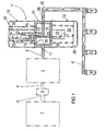
- an internal combustion engine arrangement which is preferably installed in a motor vehicle, comprises is a generally designated by the reference numeral, in Fig. 1 in a schematic manner, oil separator according to the invention, which is on the input side via a gas fuel line 2 fluidly connected to the low pressure side output of a pressure reducer 3.
- the pressure reducer 3 may, for example, be a multistage pressure reducer having a plurality of pressure chambers interconnected via respective diaphragm pressure control valves, for example an input high pressure chamber, an output low pressure chamber and an intermediate intermediate pressure pressure chamber in which, controlled by the diaphragm Pressure control valves one high, one low, and an intermediate gas pressure sets.
- a pressure reducer may also have a different number of pressure stages. The person skilled in the construction of such a pressure reducer is known, so that there is no need for further explanation here.
- the pressure reducer 3 is connected on its high pressure side via a gas fuel line 4 to a Hochdruckabsperrventil 5, through which the pressure reducer 3 supplied gaseous fuel stream can be blocked.
- the high-pressure shut-off valve 5 can be designed, for example, in the form of a main valve with an integrated pilot valve, wherein the pilot valve is designed such that it can be electromagnetically controlled with the electrical power provided by the electrical system of a motor vehicle, for example.
- an opening area of the main valve is substantially larger than that of the pilot valve, so that a correspondingly larger gas mass flow can be transported via the open main valve than via the open pilot valve.
- less force is required to open the pilot valve than to open the main valve.
- the high-pressure shut-off valve 5 is connected on the input side via a gas fuel line 6 to a gas tank 7.
- the gas tank 7 is usually provided with a separate shut-off valve, from which the gaseous fuel line 6 connected to the high-pressure shut-off valve 5 branches off.
- the oil separator 1 is connected to a gas fuel line 30, which opens into a gas fuel rail 8, which is generally referred to as a "rail".
- a gas fuel rail 8 At the end of the gas fuel rail 8 are a plurality (in Fig. 1, for example four) controllable gas injectors 9 (Gaseinblasventile) arranged through which gaseous fuel can be injected into the intake of an internal combustion engine, which is not shown in detail in Fig. 1.
- the number of gas injectors depends on the number of cylinders of the internal combustion engine, and it should be noted only for the sake of completeness that the number of gas injectors is not limited to the number 4, but depends on the specific design of the internal combustion engine.
- the oil separator 1 shown in Fig. 1 is constructed in a modular manner. It is composed of a filter module 10, a connection module 11 and an oil collection module 12.
- the filter module 10 and the oil collection module 12 are each releasably attached to the connection module 11, for example by means of respective threaded connections.
- the three modules together form the oil separator 1.
- the modules can also be connected to each other by means of other types of fastening, for example by means of spring-loaded snap or snap fasteners.
- connection module 11 is connected to the gaseous fuel line 2 by means of an inlet opening 17 which breaks through its lateral housing wall.
- the mouth 18 of the inflow opening 17 opens into one of the connection module 11 formed cavity 14.
- the cavity 14 is connected by means of formed in the housing wall of the connection module 11 openings 15 fluidly connected to a formed by the filter module 10 cavity 16.
- a hollow cylindrical shaped filter element 19 is housed, which separates the cavity 16 on the outside of the filter element 19 from a cavity 20 within the filter element 19.
- connection pipe 13 which forms with its one end an opening 21 for receiving purified gaseous fuel and is connected at its other end with a wall of the Anschussmoduls 11 breaking outflow opening 29, which in turn is connected to the gas fuel line 30 ( drawn in Fig. 1 as a continuous line).
- the mounted on the connection module 11 on the underside oil collection module 12 forms with its housing a first (outer) oil reservoir 22, in the interior of a second (inner) oil reservoir 23 is received.
- the outer oil collecting container 22 is fluidly connected to the formed by the terminal module 11 cavity 14 by means of formed in the bottom-side wall of the connection module 11 openings 24.
- the cavity 14 formed by the terminal module 11, the cavity 16 formed by the filter module 10 on the outside of the filter element 19, and the outer oil reservoir 22 collectively form an inlet space located on the upstream side ("dirty gas side") of the filter element 19
- the cavity 20 formed on the inside of the filter element 19 forms an exit space located on the outflow side ("clean gas side") of the filter element 19.
- the apertures 24 are lower in the direction of gravity than the mouth 18 of the inflow opening 17, so that of the gaseous fuel flowing into the cavity 14 separated by gravity oil components by means of the openings 24 can drain into the outer oil reservoir 22.
- the inner oil reservoir 23 is fluidly connected thereto by means of a connecting tube 25 projecting into the cavity 20.
- the mouth 26 of the connecting pipe 25 is located in the direction of gravity deeper than the mouth 21 of the connecting pipe 13, so that draining oil from the filter element 19 via the connecting pipe 25 can drain into the inner oil reservoir 23, without polluting the purified gaseous fuel.
- the two oil reservoirs 22, 23 are fluidly connected only via the filter element 19, so as to avoid a filter element 19 ausquaintde gas flow (short-circuit flow).
- the gaseous fuel flowing into the oil separator 1 through the gaseous fuel line 2 at a low gas pressure of, for example, about 8-10 bar first enters the cavity 14 formed by the terminal module 11, and is subsequently changed 90 ° counter to the direction of gravity deflected and passes through the apertures 15 in the formed by the filter module 10 on the outside of the filter element 19 cavity 16.
- liquid oil components of the gas fuel are deposited by gravity, which is as ⁇ llache 28th at the lowest point, for example at the bottom, of the outer oil collecting container 22 collect.
- the separation of the liquid oil components from the gaseous fuel stream is facilitated by deflecting the flow direction by about 90 °, so that the inflowing gas fuel is forced to flow against the direction of gravity. Since the oil separator 1 on the low pressure side of the pressure reducer 3 in the gas supply of the internal combustion engine is arranged, already condensed oil components in the gas fuel stream are easier to separate.
- the gaseous fuel flows through the filter element 19, whereby the oil components contained in the gaseous fuel, in particular in the form of an aerosol are collected, and enters the cavity 20 on the inside of the filter element 19. From there, the purified gaseous fuel via the connecting pipe 13 of the gaseous fuel line 30th fed, which feeds the gas injectors 9.
- the filter element 19 is saturated, the trapped oil is transported by the upcoming gas fuel stream to the clean gas side, that is, in the cavity 20 on the inside of the filter element 19, from where it can flow via the connecting pipe 25 into the inner oil reservoir 23.
- the oil collects in an oil layer 28 at a lowest point, for example, at the bottom of the collecting tank 23.
Landscapes
- Engineering & Computer Science (AREA)
- Chemical & Material Sciences (AREA)
- Chemical Kinetics & Catalysis (AREA)
- Mechanical Engineering (AREA)
- General Engineering & Computer Science (AREA)
- General Chemical & Material Sciences (AREA)
- Oil, Petroleum & Natural Gas (AREA)
- Combustion & Propulsion (AREA)
- Physics & Mathematics (AREA)
- Geometry (AREA)
- Lubrication Details And Ventilation Of Internal Combustion Engines (AREA)
- Filtering Of Dispersed Particles In Gases (AREA)
Abstract
Description
- Die vorliegende Erfindung liegt auf dem Gebiet der Fahrzeugtechnik und betrifft einen Ölabscheider für gasbetriebene Brennkraftmaschinen.
- Heutzutage werden zum Betreiben von gasbetriebenen Fahrzeugen hauptsächlich so genannte Flüssiggase und Erdgas eingesetzt. Flüssiggase, wie Autogas (LPG = Liquified Petroleum Gas), welche als Nebenprodukt aus Hydrierprozessen bei der Erdölraffinierung entstehen, basieren gewöhnlich auf Petroleum und bestehen im Wesentlichen aus Propan und Butan. Erdgas (CNG = Compressed Natural Gas) besteht hauptsächlich aus Methan und wird durch Förderung aus Erdgasquellen gewonnen.
- Bei mit Erdgas betriebenen Kraftfahrzeugen ist es zur Speicherung einer größeren Kraftstoffmenge erforderlich, den Gaskraftstoff im Gastank unter einem hohen Druck von beispielsweise 200-300 bar zu verdichten. Für den Betrieb der Brennkraftmaschine muss der verdichtete Gaskraftstoff dann wieder auf einen geeigneten niedrigeren Gasdruck entspannt werden, welcher meist unterhalb von 10 bar liegt und beispielsweise ca. 8 bar beträgt. Die Entspannung des Gaskraftstoffs erfolgt in einem an die Gaskraftstoffzuleitung angeschlossenen Druckminderer, von dem aus der entspannte Gasstrom jeweiligen Gaseinblasventilen ("Gasinjektoren") zum Einblasen in den Ansaugtrakt der Brennkraftmaschine zugeführt wird.
- Wie sich in der Praxis gezeigt hat, wird bei der Betankung des Kraftfahrzeugs an der Tankstelle der auf einen hohen Gasdruck verdichtete Gaskraftstoff häufig mit Schmieröl des zur Betankung eingesetzten Verdichters verunreinigt. Die Ursache hierfür ist in den immer kürzeren zeitlichen Abständen aufeinander folgender Betankungen aufgrund der stetig wachsenden Zahl gasbetriebener Kraftfahrzeuge zu finden. Dies kann dazu führen, dass in den Hochdruckstufen der Verdichter die Betriebstemperatur so stark ansteigt, dass Schmieröl verdampft und in gasförmiger Form oder als Aerosol mit dem Gaskraftstoff in den Gastank des Kraftfahrzeugs gelangt.
- Wird der Gaskraftstoff im Druckminderer auf einen Gasdruck von beispielsweise 8 bar entspannt, so kühlt sich der Gaskraftstoff während der Entspannung ab, wodurch die eingeschleppten Ölbestandteile kondensieren und in flüssiger Form bzw. als Aerosol im Gaskraftstoff enthalten sind. Strömungstechnisch bedingt, verteilt sich das im Gaskraftstoff enthaltene Öl ungleichmäßig auf die Gasinjektoren, was zu unterschiedlichen Durchflusscharakteristiken in den Gaseinblasventilen und zu Problemen in der Abgasnachbehandlung führen kann. Hierdurch können Abgasvorgaben über die Laufstrecke gegebenenfalls nicht eingehalten werden und Fahrbarkeitsprobleme auftreten. Zudem besteht die Gefahr, dass Fahrzeugkomponenten, wie beispielsweise Katalysatoren, geschädigt werden. Darüber hinaus wurde auch das Verkleben bzw. Verharzen der Gasinjektoren mit den im Gaskraftstoff enthaltenen Ölbestandteilen beobachtet.
- Um diese Probleme zu vermeiden, ist es bekannt, im Fahrzeug einen Ölabscheider in der Gaskraftstoffzuleitung zwischen dem Gastank und den Gasinjektoren vorzusehen. Gewöhnlich wird ein solcher Ölabscheider auf der Niederdruckseite des Druckminderers installiert, was die Vorteile hat, dass der Ölabscheider lediglich Druckfestigkeit gegen Niederdruck haben muss und dass das auf der Niederdruckseite des Druckmirderers kondensierte Öl in flüssiger Form beziehungsweise als Aerosol leichter abzuscheiden ist.
- Bislang eingesetzte Ölabscheider sind so konstruiert, dass der Gaskraftstoff ein Vlies-Filter durchströmt, um hierdurch die im Kraftstoff enthaltenen Ölbestandteile abzutrennen. Mittels eines Vlies-Filters lassen sich im Wesentlichen jedoch nur die in Form eines Aerosols im Gaskraftstoff enthaltenen Ölbestandteile auffangen. Ist eine größere Menge flüssigen Öls im Gaskraftstoff enthalten, so führt dies gewöhnlich zu einer schnellen Sättigung des Vlies-Filters und zu einem Nachlassen der Filterwirkung. Aufgrund des anstehenden Gasstroms kann das im Vlies-Filter enthaltene Öl auf die Reingasseite "durchschlagen", was in nachteiliger Weise zur Folge haben kann, dass der Gaskraftstoff wieder verschmutzt wird.
- Demgegenüber besteht die Aufgabe der vorliegenden Erfindung darin, einen Ölabscheider zur Verfügung zu stellen, mit welchem der Gaskraftstoff zuverlässig und sicher von Ölbestandteilen gereinigt werden kann.
- Diese Aufgabe wird nach dem Vorschlag der Erfindung durch einen Ölabscheider mit den Merkmalen des unabhängigen Anspruchs gelöst. Vorteilhafte Ausgestaltungen der Erfindung sind durch die Merkmale der Unteransprüche angegeben.
- Erfindungsgemäß ist ein Ölabscheider zum Zwecke des Abscheidens von in Gaskraftstoff enthaltenen Ölbestandteilen gezeigt, welcher zum Anschluss an eine Gaskraftstoffzuleitung einer mit Gaskraftstoff betreibbaren Brennkraftmaschine, insbesondere zum Antrieb eines Kraftfahrzeugs, bestimmt und geeignet ist.
- Der Ölabscheider umfasst ein Gehäuse mit einer Einströmöffnung für (mit Ölbestandteile verschmutzten) Gaskraftstoff und einer Ausströmöffnung für gereinigten Gaskraftstoff und ein in dem Gehäuse aufgenommenes Filterelement, beispielsweise ein Vlies-Filter, zum Filtrieren des Gas-kraftstoffs, das von dem Gaskraftstoff durchströmbar ist. Das Filterelement ist dichtend zwischen einem mit der Einströmöffnung strömungstechnisch (fluidleitend) verbundenen Eingangsraum und einem mit der Ausströmöffnung strömungstechnisch (fluidleitend) verbundenen Ausgangsraum angeordnet. Somit sind Eingangs- und Ausgangsraum lediglich über das Filterelement strömungstechnisch miteinander verbunden und ansonsten fluiddicht gegeneinander abgedichtet, so dass ein das Filterelement mit Überdruck anströmender Gaskraftstoffstrom das Filterelement ohne Umgehungsmöglichkeit passieren muss, um von dem anströmseitigen Eingangsraum in den abströmseitigen Ausgangsraum zu gelangen. Die Einströmöffnung mündet in den Eingangsraum, so dass (mit Ölbestandteilen verunreinigter) Gaskraftstoff dem Filterelement zugeleitet werden kann. Hierzu wird die Einströmöffnung an eine Gaskraftstoffzuleitung der Brennkraftmaschinenanordnung angeschlossen. Der gereinigte Gaskraftstoff im Ausgangsraum wird über die Ausströmöffnung aus dem Ölabscheider geleitet.
- Weiterhin umfasst der erfindungsgemäße Ölabscheider einen ersten Ölsammelbehälter, welcher im Eingangsraum in Schwerkraftrichtung unterhalb einer mit der Einströmöffnung strömungstechnisch verbundenen Mündung zur Abgabe von Gaskraftstoff in den Eingangsraum geformt ist und der Aufnahme von im Eingangsraum mittels Schwerkraftabscheidung aus dem Gaskraftstoff abgeschiedenen Öls dient. Der erste Ölsammelbehälter ist demnach so angeordnet, dass er mittels Schwerkraftabscheidung abgeschiedene Ölbestandteile des Gas-kraftstoffs sammeln kann. Um eine Schwerkraftabscheidung zu begünstigen, wird der über die Einströmöffnung in den Eingangsraum einströmende Gaskraftstoff vorteilhaft so umgelenkt, dass eine entgegen der Schwerkraftrichtung gerichtete vektorielle Komponente des (vektoriellen) Gasstroms eine Zunahme erfährt.
- In vorteilhafter Weise können somit mittels Schwerkraftabscheidung abscheidbare ölbestandteile aus dem strömenden Gaskraftstoff im Eingangsraum separiert und in einem Ölsammelbehälter aufgefangen werden, noch bevor der Gaskraftstoff das Filterelement erreicht. Der Eingangsraum wirkt als "Ölfalle" für die im Gaskraftstoff enthaltenen Ölbestandteile.
- Bei einer vorteilhaften Ausgestaltung des erfindungsgemäßen Ölabscheiders umfasst dieser weiterhin einen im Ausgangsraum in Schwerkraftrichtung unterhalb einer mit der Ausströmöffnung strömungstechnisch verbundenen Mündung geformten zweiten Ölsammelbehälter, welcher der Aufnahme von im Ausgangsraum von dem Filterelement ablaufenden Öl dient. Mittels des zweiten Ölsammelbehälters kann somit in vorteilhafter Weise von dem Filterelement austretendes Öl gesammelt werden, falls dieses nicht mehr in der Lage ist, das von dem Kraftstoff abfiltrierte Öl gefangen zu halten. Eine erneute Verschmutzung des Gaskraftstoffs kann vermieden werden. Der zweite Ölsammelbehälter kann insbesondere im Innern des ersten Ölsammelbehälters aufgenommen sein.
- Bei einer weiteren vorteilhaften Ausgestaltung des erfindungsgemäßen Ölabscheiders ist dieser modulartig aufgebaut. Der Ölabscheider umfasst in dieser Ausgestaltung ein das Filterelement enthaltendes Filtermodul, ein die Einström- und die Ausströmöffnung enthaltendes Anschlussmodul, sowie ein die beiden Ölsammelbehälter enthaltendes Ölsammelmodul, wobei das Filtermodul und das Ölsammelmodul jeweils am Anschlussmodul lösbar befestigt sind. Bei einem solchen modulartigen Aufbau des Ölabscheiders kann dieser in besonders einfacher Weise beispielsweise in einem Kraftfahrzeug montiert werden. Es ist hierzu lediglich notwendig, das Anschlussmodul am Kraftfahrzeug zu montieren, an eine Gaskraftstoffzuleitung der Brennkraftmaschine anzuschließen, und hiernach das Filtermodul und das Ölsammelmodul am Anschlussmodul zu befestigen. Ebenso ist eine Wartung des Ölabscheiders gemäß vorgebbarer Service-Intervalle in besonders einfacher Weise möglich, da das Filtermodul und/oder das Ölsammelmodul bei montiertem Anschlussmodul abgenommen und erneut montiert werden können, etwa um das Filterelement zu wechseln oder die Ölsammelbehälter zu leeren.
- Weiterhin erstreckt sich die Erfindung auf eine Brennkraftmaschinenanordnung, insbesondere zum Antrieb eines Kraftfahrzeugs, welche eine mit Gastkraftstoff betreibbare Brennkraftmaschine, einen Druckminderer zur Minderung des Gasdrucks des der Brennkraftmaschine zugeführten Gaskraftstoffs, welcher hochdruckseitig über eine Gaskraftstoffleitung mit wenigstens einem Gastank zum Speichern von Gaskraftstoff und niederdruckseitig durch eine Gaskraftstoffleitung mit wenigstens einem steuerbaren Gaseinblasventil zur Regelung des Gasstroms des der Brennkraftmaschine zugeführten Gaskraftstoffs fluidleitend verbunden ist, sowie einen wie oben beschriebenen Ölabscheider umfasst, wobei der Ölabscheider vorteilhaft an die niederdruckseitige Gaskraftstoffleitung angeschlossen ist.
- Des Weiteren erstreckt sich die Erfindung auf ein Kraftfahrzeug mit einer wie oben beschriebenen Brennkraftmaschinenanordnung.
- Die Erfindung wird nun anhand eines Ausführungsbeispiels näher erläutert, wobei Bezug auf die beigefügte Zeichnung genommen wird. Es zeigt:
- Fig. 1
- eine schematische Darstellung des Aufbaus eines Ausführungsbeispiels des erfindungsgemäßen Ölabscheiders in einer Brennkraftmaschinenanordnung, beispielsweise eines Kraftfahrzeugs.
- Demnach umfasst eine Brennkraftmaschinenanordnung, welche vorzugsweise in einem Kraftfahrzeug eingebaut ist, einen insgesamt mit der Bezugszahl bezeichneten, in Fig. 1 in schematischer Weise dargestellten, erfindungsgemäßen Ölabscheider, welcher eingangsseitig über eine Gaskraftstoffleitung 2 fluidleitend mit dem niederdruckseitigen Ausgang eines Druckminderers 3 verbunden ist.
- Bei dem Druckminderer 3 kann es sich beispielsweise um einen mehrstufigen Druckminderer handeln, der eine Mehrzahl von über jeweilige Membran-Druckregelventile miteinander verbundene Druckkammern aufweist, beispielsweise eine eingangsseitige Hochdruckkammer, eine ausgangsseitige Niederdruckkammer und eine zwischenliegende Zwischendruckdruckkammer, in denen sich, geregelt durch die Membran-Druckregelventile ein hoher, ein niedriger, sowie ein zwischenliegender Gasdruck einstellt. Ein solcher Druckminderer kann jedoch auch eine andere Anzahl von Druckstufen aufweisen. Dem Fachmann ist der Aufbau eines solchen Druckminderers bekannt, so dass sich eine weitere Erläuterung hier erübrigt.
- Der Druckminderer 3 ist auf seiner Hochdruckseite über eine Gaskraftstoffleitung 4 an ein Hochdruckabsperrventil 5 angeschlossen, durch das der dem Druckminderer 3 zugeführte Gaskraftstoffstrom gesperrt werden kann. Das Hochdruckabsperrventil 5 kann beispielsweise in Form eines Hauptventils mit integriertem Pilotventil ausgebildet sein, wobei das Pilotventil so ausgelegt ist, dass es mit der vom Bordnetz beispielsweise eines Kraftfahrzeugs zur Verfügung gestellten elektrischen Leistung elektromagnetisch steuerbar ist. Zu diesem Zweck ist eine Öffnungsfläche des Hauptventils wesentlich größer ausgebildet als eine solche des Pilotventils, so dass über das offene Hauptventil ein entsprechend größerer Gasmassenstrom transport werden kann als über das offene Pilotventil. In entsprechender Weise ist zur Öffnung des Pilotventils weniger Kraft erforderlich als zur Öffnung des Hauptventils. Dem Fachmann ist der Aufbau eines solchen Hochdruckabsperrventils bekannt, so dass sich eine weitere Erläuterung hier erübrigt.
- Das Hochdruckabsperrventil 5 ist eingangsseitig über eine Gaskraftstoffleitung 6 mit einem Gastank 7 verbunden. Der Gastank 7 ist gewöhnlich mit einem separaten Absperrventil versehen, von welchem die mit dem Hochdruckabsperrventil 5 eingangsseitig verbundene Gaskraftstoffleitung 6 abzweigt.
- Ausgangsseitig ist der Ölabscheider 1 an eine Gaskraftstoffleitung 30 angeschlossen, welche in eine im Allgemeinen als "Rail" bezeichnete Gaskraftstoffschiene 8 mündet. Am Ende der Gaskraftstoffschiene 8 sind eine Mehrzahl (in Fig. 1 beispielsweise vier) steuerbare Gasinjektoren 9 (Gaseinblasventile) angeordnet, durch welche Gaskraftstoff in den Ansaugtrakt einer Brennkraftmaschine eingeblasen werden kann, was in Fig. 1 nicht näher dargestellt ist. Die Anzahl der Gasinjektoren hängt von der Zylinderzahl der Brennkraftmaschine ab, und es sei lediglich der Vollständigkeit halber angemerkt, dass die Anzahl der Gasinjektoren nicht auf die Zahl 4 eingeschränkt ist, sondern von der speziellen Auslegung der Brennkraftmaschine abhängt.
- Der in Fig. 1 dargestellte Ölabscheider 1 ist modulartig aufgebaut. Er setzt sich aus einem Filtermodul 10, einem Anschlussmodul 11 und einem Ölsammelmodul 12 zusammen. Hierbei sind das Filtermodul 10 und das Ölsammelmodul 12 jeweils am Anschlussmodul 11, beispielsweise mittels jeweiliger Gewindeverbindungen, lösbar befestigt. Die drei Module formen somit gemeinsam den Ölabscheider 1. Lediglich der Vollständigkeit halber sei darauf hingewiesen, dass die Module auch mithilfe anderer Befestigungsarten miteinander verbunden werden können, beispielsweise mittels federbelasteter Schnapp- oder Rastverschlüsse.
- Das Anschlussmodul 11 ist mittels einer dessen seitliche Gehäusewandung durchbrechenden Einströmöffnung 17 an die Gaskraftstoffleitung 2 angeschlossen. Die Mündung 18 der Einströmöffnung 17 mündet in einen von dem Anschlussmodul 11 geformten Hohlraum 14. Der Hohlraum 14 ist mittels in der Gehäusewandung des Anschlussmoduls 11 geformten Durchbrechungen 15 fluidleitend mit einem von dem Filtermodul 10 geformten Hohlraum 16 verbunden. Im Filtermodul 10 ist ein hohlzylindrisch geformtes Filterelement 19 beherbergt, welches den Hohlraum 16 auf der Außenseite des Filterelements 19 von einem Hohlraum 20 innerhalb des Filterelements 19 trennt.
- In den Hohraum 20 ragt ein Anschlussrohr 13, welches mit seinem einen Ende eine Mündung 21 zum Aufnehmen von gereinigtem Gaskraftstoff formt und mit seinem anderen Ende mit einer die Wandung des Anschussmoduls 11 durchbrechenden Ausströmöffnung 29 verbunden ist, welche ihrerseits an die Gaskrafstoffleitung 30 angeschlossen ist (in Fig. 1 als durchgehende Leitung gezeichnet).
- Das am Anschlussmodul 11 auf dessen Unterseite montierte Ölsammelmodul 12 formt mit seinem Gehäuse einen ersten (äußeren) Ölsammelbehälter 22, in dessen Innern ein zweiter (innerer) Ölsammelbehälter 23 aufgenommen ist. Der äußere Ölsammelbehälter 22 ist mithilfe von in der bodenseitigen Wandung des Anschlussmoduls 11 geformten Durchbrechungen 24 fluidleitend mit dem von dem Anschlussmodul 11 geformten Hohlraum 14 verbunden. Insofern formen der von dem Anschlussmodul 11 geformte Hohlraum 14, der von dem Filtermodul 10 auf der Außenseite des Filterelements 19 geformte Hohlraum 16, sowie der äußere Ölsammelbehälter 22 gemeinsam einen auf der Anströmseite ("Schmutzgasseite") des Filterelements 19 befindlichen Eingangsraum, während der auf der Innenseite des Filterelements 19 geformte Hohlraum 20 einen auf der Abströmseite ("Reingasseite") des Filterelements 19 befindlichen Ausgangsraum formt.
- Die Durchbrechungen 24 liegen in Schwerkraftrichtung tiefer als die Mündung 18 der Einströmöffnung 17, so dass von dem in den Hohlraum 14 einströmenden Gaskraftstoff mittels Schwerkraft separierte Ölbestandteile mittels der Durchbrechungen 24 in den äußeren Ölsammelbehälter 22 ablaufen können. Der innere Ölsammelbehälter 23 ist mithilfe eines in den Hohlraum 20 ragenden Verbindungsrohrs 25 fluidleitend mit diesem verbunden. Die Mündung 26 des verbindungsrohrs 25 befindet sich in Schwerkraftrichtung tiefer als die Mündung 21 des Anschlussrohrs 13, so dass von dem Filterelement 19 abfließendes Öl über das Verbindungsrohr 25 in den inneren Ölsammelbehälter 23 ablaufen kann, ohne hierbei den gereinigten Gaskraftstoff zu verunreinigen.
- Im montierten zustand des Filtermoduls sind die beiden Ölsammelbehälter 22, 23 lediglich über das Filterelement 19 strömungstechnisch miteinander verbunden, um so eine das Filterelement 19 aussparende Gasströmung (Kurzschluss-Strömung) zu vermeiden.
- Es erfolgt nun eine Beschreibung der Funktionsweise des Ölabscheiders 1. Der durch die Gaskraftstoffleitung 2 mit einem niedrigen Gasdruck von beispielsweise ca. 8-10 bar in den Ölabscheider 1 einströmende Gaskraftstoff tritt zunächst in den von dem Anschlussmodul 11 geformten Hohlraum 14 ein, wird anschließend um ca. 90° entgegen der Schwerkraftrichtung umgelenkt und gelangt durch Passieren der Durchbrechungen 15 in den von dem Filtermodul 10 auf der Außenseite des Filterelements 19 geformten Hohlraum 16. Im Wesentlichen im Hohlraum 14 werden flüssige Ölbestandteile des Gaskraftstoffs durch Schwerkraft abgeschieden, welche sich als Öllache 28 an der tiefsten Stelle, beispielsweise am Boden, des äußeren Ölsammelbehälters 22 sammeln. Die Abscheidung der flüssigen Ölbestandteile aus dem Gaskraftstoffstrom wird durch Umlenken der Strömungsrichtung um ca. 90°, so dass der einströmende Gaskraftstoff gezwungen ist, entgegen der Schwerkraftrichtung zu strömen, begünstigt. Da der Ölabscheider 1 auf der Niederdruckseite des Druckminderers 3 in der Gaszuführung der Brennkraftmaschine angeordnet ist, sind bereits kondensierte Ölbestandteile im Gaskraftstoffstrom leichter abzuscheiden.
- Anschließend durchströmt der Gaskraftstoff das Filterelement 19, wodurch die im Gaskraftstoff, insbesondere in Form eines Aerosols, enthaltenen Ölbestandteile aufgefangen werden, und gelangt in den Hohlraum 20 auf der Innenseite des Filterelements 19. Von dort wird der gereinigte Gaskraftstoff über das Anschlussrohr 13 der Gaskraftstoffleitung 30 zugeführt, welche die Gasinjektoren 9 speist. Wenn das Filterelement 19 gesättigt ist, wird das gefangene öl durch den anstehenden Gaskraftstoffstrom zur Reingasseite, das heißt, in den Hohlraum 20 auf der Innenseite des Filterelements 19 transportiert, von wo es über das Verbindungsrohr 25 in den inneren Ölsammelbehälter 23 abfließen kann. Im Ölsammelbehälter 23 sammelt sich das Öl in einer Öllache 28 an einer tiefsten Stelle, beispielsweise am Boden des Sammelbehälters 23.
-
- 1
- Ölabscheider
- 2
- Gaskraftstoffleitung
- 3
- Druckminderer
- 4
- Gaskraftstoffleitung
- 5
- Hochdruckabsperrventil
- 6
- Gaskraftstoffleitung
- 7
- Gastank
- 8
- Rail
- 9
- Gasinjektor
- 10
- Filtermodul
- 11
- Anschlussmodul
- 12
- Ölsammelmodul
- 13
- Anschlussrohr
- 14
- Hohlraum
- 15
- Durchbrechung
- 16
- Hohlraum
- 17
- Einströmöffnung
- 18
- Mündung
- 19
- Filterelement
- 20
- Hohlraum
- 21
- Mündung
- 22
- Ölsammelbehälter
- 23
- Ölsammelbehälter
- 24
- Durchbrechung
- 25
- Verbindungsrohr
- 26
- Mündung
- 27
- Öllache
- 28
- Öllache
- 29
- Ausströmöffnung
- 30
- Gaskraftstoffleitung
Claims (8)
- Ölabscheider (1) zum Abscheiden von in Gaskraftstoff enthaltenen Ölbestandteilen zum Anschluss an eine Gaskraftstoffleitung (2) einer gasbetriebenen Brennkraftmaschine, welcher umfasst:ein Gehäuse mit einer Einströmöffnung (17) und einer Ausströmöffnung (29) für Gaskraftstoff,- ein im Gehäuse aufgenommenes, von dem Gaskraftstoff durchströmbares Filterelement (19), das dichtend zwischen einem mit der Einströmöffnung (17) strömungstechnisch verbundenen Eingangsraum (14, 16, 22) und einem mit der Ausströmöffnung (29) strömungstechnisch verbundenen Ausgangsraum (20) angeordnet ist,- einen in dem Eingangsraum in Schwerkraftrichtung unterhalb einer mit der Einströmöffnung strömungstechnisch verbundenen Mündung (18) zur Abgabe von Gaskraftstoff in den Eingangsraum geformten ersten Ölsammelbehälter (22) zur Aufnahme von im Eingangsraum mittels Schwerkraftabscheidung aus dem Gaskraftstoff abgeschiedenen Öls.
- Ölabscheider nach Anspruch 1,
welche derart ausgebildet ist, dass ein Gaskraftstoffstrom des in den Eingangsraum einströmenden Gaskraftstoffs eine Zunahme einer entgegen der Schwerkraftrichtung gerichteten vektoriellen Strömungskomponente erfährt. - Ölabscheider nach einem der vorhergehenden Ansprüche 1 bis 2, welcher weiterhin einen, im Ausgangsraum in Schwerkraftrichtung unterhalb einer mit der Ausströmöffnung (29) strömungstechnisch verbundenen Mündung (21) geformten, zweiten Ölsammelbehälter (23) zur Aufnahme von im Ausgangsraum (20) von dem Filterelement ablaufenden Öl umfasst.
- Ölabscheider nach Anspruch 3,
bei welchem der zweite Ölsammelbehälter (23) innerhalb des ersten Ölsammelbehälters (22) angeordnet ist. - Ölabscheider nach einem der Ansprüche 3 bis 4 mit einem modularen Aufbau, welcher- ein das Filterelement (19) enthaltendes Filtermodul (10),- ein die Einström- und die Ausströmöffnungen (17, 29) enthaltendes Anschlussmodul (11), und- ein die beiden Ölsammelbehälter (22, 23) enthaltendes Ölsammelmodul (12) umfasst, wobei
das Filtermodul und das Ölsammelmodul jeweils am Anschlussmodul lösbar befestigt sind. - Brennkraftmaschinenanordnung, insbesondere zum Antrieb eines Kraftfahrzeugs, welche umfasst:- eine mit Gastkraftstoff betreibbare Brennkraftmaschine,- einen Druckminderer (3) zur Minderung des Gasdrucks des der Brennkraftmaschine zugeführten Gaskraftstoffs, welcher hochdruckseitig über eine Gaskraftstoffleitung (4, 6) mit wenigstens einem Gastank (7) zum Speichern von Gaskraftstoff und niederdruckseitig durch eine Gaskraftstoffleitung (2, 30, 8) mit wenigstens einem steuerbaren Gaseinblasventil (9) zur Regelung des Gasstroms des der Brennkraftmaschine zugeführten Gaskraftstoffs fluidleitend verbunden ist, wobei die Brennkraftmaschinenanordnung einen Ölabscheider (1) nach einem der vorhergehenden Ansprüche 1 bis 5 umfasst.
- Brennkraftmaschinenanordnung nach Anspruch 6, bei welcher der Ölabscheider (1) auf der Niederdruckseite des Druckminderers (3) angeordnet ist.
- Kraftfahrzeug mit einer Brennkraftmaschinenanordnung nach einem der Ansprüche 6 bis 7.
Priority Applications (10)
| Application Number | Priority Date | Filing Date | Title |
|---|---|---|---|
| AT06015968T ATE444441T1 (de) | 2006-08-01 | 2006-08-01 | Ölabscheider für gasbetriebene brennkraftmaschinen |
| EP06015968A EP1884651B1 (de) | 2006-08-01 | 2006-08-01 | Ölabscheider für gasbetriebene Brennkraftmaschinen |
| DE502006004984T DE502006004984D1 (de) | 2006-08-01 | 2006-08-01 | Ölabscheider für gasbetriebene Brennkraftmaschinen |
| BRPI0715340 BRPI0715340A2 (pt) | 2006-08-01 | 2007-07-27 | Separador de óleo para máquinas de combustão interna operadas a gás. |
| RU2009107108/06A RU2442012C2 (ru) | 2006-08-01 | 2007-07-27 | Маслоотделитель для работающих на газовом топливе двигателей внутреннего сгорания |
| AU2007280739A AU2007280739A1 (en) | 2006-08-01 | 2007-07-27 | Oil separator for gas-powered internal combustion engines |
| PCT/EP2007/006679 WO2008014939A1 (de) | 2006-08-01 | 2007-07-27 | Ölabscheider für gasbetriebene brennkraftmaschinen |
| CN2007800349275A CN101517220B (zh) | 2006-08-01 | 2007-07-27 | 用气体燃料工作的内燃机的油分离器 |
| KR1020097004405A KR20090043549A (ko) | 2006-08-01 | 2007-07-27 | 가스 동력 내부 연소 엔진용 오일 분리기 |
| US12/375,919 US8534266B2 (en) | 2006-08-01 | 2007-07-27 | Oil separator for gas-powered combustion engines |
Applications Claiming Priority (1)
| Application Number | Priority Date | Filing Date | Title |
|---|---|---|---|
| EP06015968A EP1884651B1 (de) | 2006-08-01 | 2006-08-01 | Ölabscheider für gasbetriebene Brennkraftmaschinen |
Publications (2)
| Publication Number | Publication Date |
|---|---|
| EP1884651A1 true EP1884651A1 (de) | 2008-02-06 |
| EP1884651B1 EP1884651B1 (de) | 2009-09-30 |
Family
ID=37561123
Family Applications (1)
| Application Number | Title | Priority Date | Filing Date |
|---|---|---|---|
| EP06015968A Not-in-force EP1884651B1 (de) | 2006-08-01 | 2006-08-01 | Ölabscheider für gasbetriebene Brennkraftmaschinen |
Country Status (10)
| Country | Link |
|---|---|
| US (1) | US8534266B2 (de) |
| EP (1) | EP1884651B1 (de) |
| KR (1) | KR20090043549A (de) |
| CN (1) | CN101517220B (de) |
| AT (1) | ATE444441T1 (de) |
| AU (1) | AU2007280739A1 (de) |
| BR (1) | BRPI0715340A2 (de) |
| DE (1) | DE502006004984D1 (de) |
| RU (1) | RU2442012C2 (de) |
| WO (1) | WO2008014939A1 (de) |
Cited By (3)
| Publication number | Priority date | Publication date | Assignee | Title |
|---|---|---|---|---|
| CN104254680A (zh) * | 2012-03-22 | 2014-12-31 | 爱三工业株式会社 | 油分离器及气体燃料供给装置 |
| EP2940284A4 (de) * | 2012-11-26 | 2016-11-23 | Aisan Ind | Vorrichtung zur bestimmung einer öllagermenge |
| CN111377062A (zh) * | 2020-04-15 | 2020-07-07 | 重庆耐德工业股份有限公司 | 集成式航空供油设备 |
Families Citing this family (10)
| Publication number | Priority date | Publication date | Assignee | Title |
|---|---|---|---|---|
| US8991423B2 (en) | 2010-05-10 | 2015-03-31 | Go Natural Cng, Llc | Fuel interface modules and related systems and methods |
| CN102022228B (zh) * | 2010-12-14 | 2012-08-22 | 奇瑞汽车股份有限公司 | 一种天然气汽车燃气过滤装置 |
| DE102011009232A1 (de) | 2011-01-22 | 2012-07-26 | Hydac Filtertechnik Gmbh | Vorrichtung zum Abscheiden von in gasförmigen Medien enthaltenen Fluiden, insbesondere Öl aus Gaskraftstoffen für Verbrennungsmotoren |
| JP2015014235A (ja) * | 2013-07-04 | 2015-01-22 | 愛三工業株式会社 | フィルタ装置及び圧力調整器 |
| EP3068832B1 (de) * | 2013-11-14 | 2022-11-02 | Ems-Chemie Ag | Polyamidformmassen für grosse formteile |
| CN104088792B (zh) * | 2014-06-23 | 2017-03-15 | 珠海格力电器股份有限公司 | 螺杆压缩机的油分离器及螺杆压缩机 |
| DE102014014098A1 (de) * | 2014-09-30 | 2016-03-31 | Mankiewicz Gebr. & Co. Gmbh & Co. Kg | Sperrschicht und deren Verwendung in Beschichtungssystemen auf Kunststoffsubstraten |
| US10012119B1 (en) * | 2015-08-10 | 2018-07-03 | Gilberto Mesa | Positive crankcase ventilation gas diversion and reclamation system |
| US10006385B1 (en) * | 2015-08-10 | 2018-06-26 | Gilberto Mesa | Positive crankcase ventilation gas diversion system |
| JP2023004675A (ja) * | 2021-06-28 | 2023-01-17 | マーレジャパン株式会社 | 内燃機関用潤滑油の希釈抑制装置 |
Citations (6)
| Publication number | Priority date | Publication date | Assignee | Title |
|---|---|---|---|---|
| US3577726A (en) * | 1969-07-24 | 1971-05-04 | Caterpillar Tractor Co | Fuel system for natural gas turbocharged engine |
| FR2566844A1 (fr) * | 1984-06-29 | 1986-01-03 | Bedini Spa | Appareillage pour l'elimination des residus solides qui s'entassent dans des dispositifs filtrants |
| US4690759A (en) * | 1986-10-14 | 1987-09-01 | Frick Company | Centrifugal and impingement oil separator |
| JPH09228897A (ja) * | 1996-02-22 | 1997-09-02 | Nippon Carbureter Co Ltd | 気体燃料フイルタ |
| JP2000205050A (ja) * | 1999-01-13 | 2000-07-25 | Toyota Motor Corp | 気体燃料車 |
| GB2376193A (en) * | 2001-01-16 | 2002-12-11 | Toyo Roki Seizo Kk | Oil mist filter |
Family Cites Families (9)
| Publication number | Priority date | Publication date | Assignee | Title |
|---|---|---|---|---|
| RU2036317C1 (ru) * | 1992-12-16 | 1995-05-27 | Производственное объединение "Турбомоторный завод" | Маслоотделитель системы вентиляции картера двигателя внутреннего сгорания |
| DE4305122A1 (de) * | 1993-02-19 | 1994-08-25 | Mann & Hummel Filter | Ölabscheider für die Gase des Kurbelgehäuses einer Brennkraftmaschine |
| EP1241327A1 (de) * | 2001-03-13 | 2002-09-18 | Mitsubishi Heavy Industries, Ltd. | Ölabscheider |
| ITMI20021793A1 (it) * | 2002-08-06 | 2004-02-07 | Landi Renzo Spa | Sistema di alimentazione e controllo perfezionato di un motore a combustione interna alimentato da due diversi combustibili |
| RU2003132222A (ru) * | 2003-11-03 | 2005-05-20 | Борис Петрович Чоповский (RU) | Двигатель внутреннего сгорания (варианты) |
| CN2688910Y (zh) * | 2004-04-06 | 2005-03-30 | 孙维东 | 燃气发动机的供气装置 |
| US7059311B2 (en) * | 2004-08-12 | 2006-06-13 | Shiloh Industries, Inc. | Air/oil separating device |
| DE102006025857A1 (de) * | 2006-06-02 | 2007-12-06 | GM Global Technology Operations, Inc., Detroit | Verfahren zum Betrieb einer Brennkraftmaschinenanordnung |
| DE102006036116A1 (de) | 2006-08-01 | 2008-02-28 | GM Global Technology Operations, Inc., Detroit | Druckminderer mit Ölabscheidefunktion für gasbetriebene Brennkraftmaschinen |
-
2006
- 2006-08-01 EP EP06015968A patent/EP1884651B1/de not_active Not-in-force
- 2006-08-01 AT AT06015968T patent/ATE444441T1/de active
- 2006-08-01 DE DE502006004984T patent/DE502006004984D1/de active Active
-
2007
- 2007-07-27 WO PCT/EP2007/006679 patent/WO2008014939A1/de not_active Ceased
- 2007-07-27 AU AU2007280739A patent/AU2007280739A1/en not_active Abandoned
- 2007-07-27 CN CN2007800349275A patent/CN101517220B/zh not_active Expired - Fee Related
- 2007-07-27 BR BRPI0715340 patent/BRPI0715340A2/pt not_active IP Right Cessation
- 2007-07-27 KR KR1020097004405A patent/KR20090043549A/ko not_active Withdrawn
- 2007-07-27 US US12/375,919 patent/US8534266B2/en not_active Expired - Fee Related
- 2007-07-27 RU RU2009107108/06A patent/RU2442012C2/ru not_active IP Right Cessation
Patent Citations (6)
| Publication number | Priority date | Publication date | Assignee | Title |
|---|---|---|---|---|
| US3577726A (en) * | 1969-07-24 | 1971-05-04 | Caterpillar Tractor Co | Fuel system for natural gas turbocharged engine |
| FR2566844A1 (fr) * | 1984-06-29 | 1986-01-03 | Bedini Spa | Appareillage pour l'elimination des residus solides qui s'entassent dans des dispositifs filtrants |
| US4690759A (en) * | 1986-10-14 | 1987-09-01 | Frick Company | Centrifugal and impingement oil separator |
| JPH09228897A (ja) * | 1996-02-22 | 1997-09-02 | Nippon Carbureter Co Ltd | 気体燃料フイルタ |
| JP2000205050A (ja) * | 1999-01-13 | 2000-07-25 | Toyota Motor Corp | 気体燃料車 |
| GB2376193A (en) * | 2001-01-16 | 2002-12-11 | Toyo Roki Seizo Kk | Oil mist filter |
Cited By (4)
| Publication number | Priority date | Publication date | Assignee | Title |
|---|---|---|---|---|
| CN104254680A (zh) * | 2012-03-22 | 2014-12-31 | 爱三工业株式会社 | 油分离器及气体燃料供给装置 |
| EP2829704A4 (de) * | 2012-03-22 | 2016-04-13 | Aisan Ind | Ölabscheider und vorrichtung zur zuführung von gasförmigem brennstoff |
| EP2940284A4 (de) * | 2012-11-26 | 2016-11-23 | Aisan Ind | Vorrichtung zur bestimmung einer öllagermenge |
| CN111377062A (zh) * | 2020-04-15 | 2020-07-07 | 重庆耐德工业股份有限公司 | 集成式航空供油设备 |
Also Published As
| Publication number | Publication date |
|---|---|
| US20100012097A1 (en) | 2010-01-21 |
| ATE444441T1 (de) | 2009-10-15 |
| WO2008014939A1 (de) | 2008-02-07 |
| RU2009107108A (ru) | 2010-09-10 |
| CN101517220A (zh) | 2009-08-26 |
| DE502006004984D1 (de) | 2009-11-12 |
| CN101517220B (zh) | 2011-08-17 |
| KR20090043549A (ko) | 2009-05-06 |
| RU2442012C2 (ru) | 2012-02-10 |
| AU2007280739A1 (en) | 2008-02-07 |
| EP1884651B1 (de) | 2009-09-30 |
| BRPI0715340A2 (pt) | 2015-03-24 |
| US8534266B2 (en) | 2013-09-17 |
Similar Documents
| Publication | Publication Date | Title |
|---|---|---|
| WO2008014939A1 (de) | Ölabscheider für gasbetriebene brennkraftmaschinen | |
| WO2007140912A1 (de) | Verfahren zum betrieb einer brennkraftmaschinenanordnung | |
| EP2439396B1 (de) | Kraftstofffiltersystem eines Kraftstoffsystems einer Brennkraftmaschine und Verfahren zur Abscheidung von Wasser aus Kraftstoff | |
| DE102004011282A1 (de) | Kraftstoffeinspritzeinrichtung für eine Brennkraftmaschine | |
| DE102012200706A1 (de) | Kraftstoffeinspritzvorrichtung für eine Brennkraftmaschine | |
| DE102011117158B4 (de) | Tanksystem für ein Kraftfahrzeug sowie Betriebsverfahren hierfür | |
| DE102009052597A1 (de) | Kraftstoffeinspritzanlage | |
| WO2017174118A1 (de) | Kraftstoffaustausch- und kraftstoffförder-system für kraftstoffanlagen | |
| DE10334042A1 (de) | Einrichtung zum Erzeugen eines Unterdrucks an einer Brennkraftmaschine | |
| DE102014007302A1 (de) | Filtervorrichtung | |
| WO2006034889A1 (de) | Kraftstoffversorgungseinrichtung für eine brennkraftmaschine | |
| EP2478949A2 (de) | Vorrichtung zum Abscheiden von in gasförmigen Medien enthaltenen Fluiden, insbesondere öl aus Gaskraftstoffen für Verbrennungsmotoren | |
| DE102019101181A1 (de) | Verfahren zur Regeneration eines Aktivkohlefilters sowie Verbrennungsmotor | |
| DE102009001564B4 (de) | Drosselelement | |
| DE102013008987A1 (de) | Filterelement | |
| WO2017167504A1 (de) | Wassereinspritzvorrichtung einer brennkraftmaschine eines fahrzeugs | |
| DE10252474B4 (de) | Brennkraftmaschine mit Abgasturbolader | |
| EP3036425A1 (de) | Kraftstoff-fördersystem | |
| EP4321740A2 (de) | Einrichtung zur saugfiltration von fluiden | |
| DE102006036116A1 (de) | Druckminderer mit Ölabscheidefunktion für gasbetriebene Brennkraftmaschinen | |
| DE102009052601A1 (de) | Kraftstoffeinspritzanlage | |
| DE20318633U1 (de) | Einrichtung für die Rück- oder Abführung und die Entölung des Kurbelgehäuse-Entlüftungsgases einer Brennkraftmaschine | |
| DE102005011026B4 (de) | Einrichtung zur Trennung eines Kraftstoff-/Luftgemischs und Abscheidung von Kraftstoff aus diesem Gemisch | |
| AT527419B1 (de) | Entgasungssystem für einen Kraftstofftank | |
| DE102016200421A1 (de) | Kraftstofffilter in einem Kraftstoffeinspritzsystem |
Legal Events
| Date | Code | Title | Description |
|---|---|---|---|
| PUAI | Public reference made under article 153(3) epc to a published international application that has entered the european phase |
Free format text: ORIGINAL CODE: 0009012 |
|
| AK | Designated contracting states |
Kind code of ref document: A1 Designated state(s): AT BE BG CH CY CZ DE DK EE ES FI FR GB GR HU IE IS IT LI LT LU LV MC NL PL PT RO SE SI SK TR |
|
| AX | Request for extension of the european patent |
Extension state: AL BA HR MK YU |
|
| 17P | Request for examination filed |
Effective date: 20080527 |
|
| 17Q | First examination report despatched |
Effective date: 20080721 |
|
| AKX | Designation fees paid |
Designated state(s): AT BE BG CH CY CZ DE DK EE ES FI FR GB GR HU IE IS IT LI LT LU LV MC NL PL PT RO SE SI SK TR |
|
| GRAP | Despatch of communication of intention to grant a patent |
Free format text: ORIGINAL CODE: EPIDOSNIGR1 |
|
| GRAS | Grant fee paid |
Free format text: ORIGINAL CODE: EPIDOSNIGR3 |
|
| GRAA | (expected) grant |
Free format text: ORIGINAL CODE: 0009210 |
|
| AK | Designated contracting states |
Kind code of ref document: B1 Designated state(s): AT BE BG CH CY CZ DE DK EE ES FI FR GB GR HU IE IS IT LI LT LU LV MC NL PL PT RO SE SI SK TR |
|
| REG | Reference to a national code |
Ref country code: CH Ref legal event code: EP Ref country code: GB Ref legal event code: FG4D Free format text: NOT ENGLISH |
|
| REG | Reference to a national code |
Ref country code: IE Ref legal event code: FG4D |
|
| REF | Corresponds to: |
Ref document number: 502006004984 Country of ref document: DE Date of ref document: 20091112 Kind code of ref document: P |
|
| PG25 | Lapsed in a contracting state [announced via postgrant information from national office to epo] |
Ref country code: SE Free format text: LAPSE BECAUSE OF FAILURE TO SUBMIT A TRANSLATION OF THE DESCRIPTION OR TO PAY THE FEE WITHIN THE PRESCRIBED TIME-LIMIT Effective date: 20090930 Ref country code: LT Free format text: LAPSE BECAUSE OF FAILURE TO SUBMIT A TRANSLATION OF THE DESCRIPTION OR TO PAY THE FEE WITHIN THE PRESCRIBED TIME-LIMIT Effective date: 20090930 Ref country code: FI Free format text: LAPSE BECAUSE OF FAILURE TO SUBMIT A TRANSLATION OF THE DESCRIPTION OR TO PAY THE FEE WITHIN THE PRESCRIBED TIME-LIMIT Effective date: 20090930 |
|
| LTIE | Lt: invalidation of european patent or patent extension |
Effective date: 20090930 |
|
| PG25 | Lapsed in a contracting state [announced via postgrant information from national office to epo] |
Ref country code: PL Free format text: LAPSE BECAUSE OF FAILURE TO SUBMIT A TRANSLATION OF THE DESCRIPTION OR TO PAY THE FEE WITHIN THE PRESCRIBED TIME-LIMIT Effective date: 20090930 Ref country code: SI Free format text: LAPSE BECAUSE OF FAILURE TO SUBMIT A TRANSLATION OF THE DESCRIPTION OR TO PAY THE FEE WITHIN THE PRESCRIBED TIME-LIMIT Effective date: 20090930 Ref country code: LV Free format text: LAPSE BECAUSE OF FAILURE TO SUBMIT A TRANSLATION OF THE DESCRIPTION OR TO PAY THE FEE WITHIN THE PRESCRIBED TIME-LIMIT Effective date: 20090930 |
|
| NLV1 | Nl: lapsed or annulled due to failure to fulfill the requirements of art. 29p and 29m of the patents act | ||
| PG25 | Lapsed in a contracting state [announced via postgrant information from national office to epo] |
Ref country code: CZ Free format text: LAPSE BECAUSE OF FAILURE TO SUBMIT A TRANSLATION OF THE DESCRIPTION OR TO PAY THE FEE WITHIN THE PRESCRIBED TIME-LIMIT Effective date: 20090930 Ref country code: EE Free format text: LAPSE BECAUSE OF FAILURE TO SUBMIT A TRANSLATION OF THE DESCRIPTION OR TO PAY THE FEE WITHIN THE PRESCRIBED TIME-LIMIT Effective date: 20090930 Ref country code: RO Free format text: LAPSE BECAUSE OF FAILURE TO SUBMIT A TRANSLATION OF THE DESCRIPTION OR TO PAY THE FEE WITHIN THE PRESCRIBED TIME-LIMIT Effective date: 20090930 Ref country code: IS Free format text: LAPSE BECAUSE OF FAILURE TO SUBMIT A TRANSLATION OF THE DESCRIPTION OR TO PAY THE FEE WITHIN THE PRESCRIBED TIME-LIMIT Effective date: 20100130 Ref country code: ES Free format text: LAPSE BECAUSE OF FAILURE TO SUBMIT A TRANSLATION OF THE DESCRIPTION OR TO PAY THE FEE WITHIN THE PRESCRIBED TIME-LIMIT Effective date: 20100110 Ref country code: PT Free format text: LAPSE BECAUSE OF FAILURE TO SUBMIT A TRANSLATION OF THE DESCRIPTION OR TO PAY THE FEE WITHIN THE PRESCRIBED TIME-LIMIT Effective date: 20100201 |
|
| REG | Reference to a national code |
Ref country code: IE Ref legal event code: FD4D |
|
| PG25 | Lapsed in a contracting state [announced via postgrant information from national office to epo] |
Ref country code: SK Free format text: LAPSE BECAUSE OF FAILURE TO SUBMIT A TRANSLATION OF THE DESCRIPTION OR TO PAY THE FEE WITHIN THE PRESCRIBED TIME-LIMIT Effective date: 20090930 |
|
| PG25 | Lapsed in a contracting state [announced via postgrant information from national office to epo] |
Ref country code: DK Free format text: LAPSE BECAUSE OF FAILURE TO SUBMIT A TRANSLATION OF THE DESCRIPTION OR TO PAY THE FEE WITHIN THE PRESCRIBED TIME-LIMIT Effective date: 20090930 Ref country code: IE Free format text: LAPSE BECAUSE OF FAILURE TO SUBMIT A TRANSLATION OF THE DESCRIPTION OR TO PAY THE FEE WITHIN THE PRESCRIBED TIME-LIMIT Effective date: 20090930 Ref country code: NL Free format text: LAPSE BECAUSE OF FAILURE TO SUBMIT A TRANSLATION OF THE DESCRIPTION OR TO PAY THE FEE WITHIN THE PRESCRIBED TIME-LIMIT Effective date: 20090930 |
|
| PLBE | No opposition filed within time limit |
Free format text: ORIGINAL CODE: 0009261 |
|
| STAA | Information on the status of an ep patent application or granted ep patent |
Free format text: STATUS: NO OPPOSITION FILED WITHIN TIME LIMIT |
|
| 26N | No opposition filed |
Effective date: 20100701 |
|
| PG25 | Lapsed in a contracting state [announced via postgrant information from national office to epo] |
Ref country code: GR Free format text: LAPSE BECAUSE OF FAILURE TO SUBMIT A TRANSLATION OF THE DESCRIPTION OR TO PAY THE FEE WITHIN THE PRESCRIBED TIME-LIMIT Effective date: 20091231 |
|
| BERE | Be: lapsed |
Owner name: GM GLOBAL TECHNOLOGY OPERATIONS, INC. Effective date: 20100831 |
|
| PG25 | Lapsed in a contracting state [announced via postgrant information from national office to epo] |
Ref country code: MC Free format text: LAPSE BECAUSE OF NON-PAYMENT OF DUE FEES Effective date: 20100831 |
|
| REG | Reference to a national code |
Ref country code: CH Ref legal event code: PL |
|
| PG25 | Lapsed in a contracting state [announced via postgrant information from national office to epo] |
Ref country code: LI Free format text: LAPSE BECAUSE OF NON-PAYMENT OF DUE FEES Effective date: 20100831 Ref country code: CH Free format text: LAPSE BECAUSE OF NON-PAYMENT OF DUE FEES Effective date: 20100831 |
|
| REG | Reference to a national code |
Ref country code: DE Ref legal event code: R081 Ref document number: 502006004984 Country of ref document: DE Owner name: GM GLOBAL TECHNOLOGY OPERATIONS LLC (N. D. GES, US Free format text: FORMER OWNER: GM GLOBAL TECHNOLOGY OPERATIONS, INC., DETROIT, MICH., US Effective date: 20110323 |
|
| PG25 | Lapsed in a contracting state [announced via postgrant information from national office to epo] |
Ref country code: BE Free format text: LAPSE BECAUSE OF NON-PAYMENT OF DUE FEES Effective date: 20100831 |
|
| PG25 | Lapsed in a contracting state [announced via postgrant information from national office to epo] |
Ref country code: CY Free format text: LAPSE BECAUSE OF FAILURE TO SUBMIT A TRANSLATION OF THE DESCRIPTION OR TO PAY THE FEE WITHIN THE PRESCRIBED TIME-LIMIT Effective date: 20090930 |
|
| PG25 | Lapsed in a contracting state [announced via postgrant information from national office to epo] |
Ref country code: LU Free format text: LAPSE BECAUSE OF NON-PAYMENT OF DUE FEES Effective date: 20100801 Ref country code: HU Free format text: LAPSE BECAUSE OF FAILURE TO SUBMIT A TRANSLATION OF THE DESCRIPTION OR TO PAY THE FEE WITHIN THE PRESCRIBED TIME-LIMIT Effective date: 20100401 Ref country code: BG Free format text: LAPSE BECAUSE OF FAILURE TO SUBMIT A TRANSLATION OF THE DESCRIPTION OR TO PAY THE FEE WITHIN THE PRESCRIBED TIME-LIMIT Effective date: 20090930 |
|
| PG25 | Lapsed in a contracting state [announced via postgrant information from national office to epo] |
Ref country code: TR Free format text: LAPSE BECAUSE OF FAILURE TO SUBMIT A TRANSLATION OF THE DESCRIPTION OR TO PAY THE FEE WITHIN THE PRESCRIBED TIME-LIMIT Effective date: 20090930 |
|
| REG | Reference to a national code |
Ref country code: AT Ref legal event code: MM01 Ref document number: 444441 Country of ref document: AT Kind code of ref document: T Effective date: 20110801 |
|
| PG25 | Lapsed in a contracting state [announced via postgrant information from national office to epo] |
Ref country code: AT Free format text: LAPSE BECAUSE OF NON-PAYMENT OF DUE FEES Effective date: 20110801 |
|
| REG | Reference to a national code |
Ref country code: FR Ref legal event code: PLFP Year of fee payment: 11 |
|
| PGFP | Annual fee paid to national office [announced via postgrant information from national office to epo] |
Ref country code: GB Payment date: 20160727 Year of fee payment: 11 Ref country code: IT Payment date: 20160822 Year of fee payment: 11 |
|
| PGFP | Annual fee paid to national office [announced via postgrant information from national office to epo] |
Ref country code: FR Payment date: 20160712 Year of fee payment: 11 |
|
| GBPC | Gb: european patent ceased through non-payment of renewal fee |
Effective date: 20170801 |
|
| REG | Reference to a national code |
Ref country code: FR Ref legal event code: ST Effective date: 20180430 |
|
| PG25 | Lapsed in a contracting state [announced via postgrant information from national office to epo] |
Ref country code: GB Free format text: LAPSE BECAUSE OF NON-PAYMENT OF DUE FEES Effective date: 20170801 |
|
| PG25 | Lapsed in a contracting state [announced via postgrant information from national office to epo] |
Ref country code: FR Free format text: LAPSE BECAUSE OF NON-PAYMENT OF DUE FEES Effective date: 20170831 Ref country code: IT Free format text: LAPSE BECAUSE OF NON-PAYMENT OF DUE FEES Effective date: 20170801 |
|
| PGFP | Annual fee paid to national office [announced via postgrant information from national office to epo] |
Ref country code: DE Payment date: 20200722 Year of fee payment: 15 |
|
| REG | Reference to a national code |
Ref country code: DE Ref legal event code: R119 Ref document number: 502006004984 Country of ref document: DE |
|
| PG25 | Lapsed in a contracting state [announced via postgrant information from national office to epo] |
Ref country code: DE Free format text: LAPSE BECAUSE OF NON-PAYMENT OF DUE FEES Effective date: 20220301 |