EP1886200B1 - Distributeur - Google Patents
Distributeur Download PDFInfo
- Publication number
- EP1886200B1 EP1886200B1 EP06751725A EP06751725A EP1886200B1 EP 1886200 B1 EP1886200 B1 EP 1886200B1 EP 06751725 A EP06751725 A EP 06751725A EP 06751725 A EP06751725 A EP 06751725A EP 1886200 B1 EP1886200 B1 EP 1886200B1
- Authority
- EP
- European Patent Office
- Prior art keywords
- fluid
- housing
- dispenser
- chamber
- rotatable member
- Prior art date
- Legal status (The legal status is an assumption and is not a legal conclusion. Google has not performed a legal analysis and makes no representation as to the accuracy of the status listed.)
- Expired - Lifetime
Links
Images


Classifications
-
- B—PERFORMING OPERATIONS; TRANSPORTING
- B65—CONVEYING; PACKING; STORING; HANDLING THIN OR FILAMENTARY MATERIAL
- B65D—CONTAINERS FOR STORAGE OR TRANSPORT OF ARTICLES OR MATERIALS, e.g. BAGS, BARRELS, BOTTLES, BOXES, CANS, CARTONS, CRATES, DRUMS, JARS, TANKS, HOPPERS, FORWARDING CONTAINERS; ACCESSORIES, CLOSURES, OR FITTINGS THEREFOR; PACKAGING ELEMENTS; PACKAGES
- B65D41/00—Caps, e.g. crown caps or crown seals, i.e. members having parts arranged for engagement with the external periphery of a neck or wall defining a pouring opening or discharge aperture; Protective cap-like covers for closure members, e.g. decorative covers of metal foil or paper
- B65D41/02—Caps or cap-like covers without lines of weakness, tearing strips, tags, or like opening or removal devices
- B65D41/04—Threaded or like caps or cap-like covers secured by rotation
- B65D41/0485—Threaded or like caps or cap-like covers secured by rotation with means specially adapted for facilitating the operation of opening or closing
-
- C—CHEMISTRY; METALLURGY
- C02—TREATMENT OF WATER, WASTE WATER, SEWAGE, OR SLUDGE
- C02F—TREATMENT OF WATER, WASTE WATER, SEWAGE, OR SLUDGE
- C02F1/00—Treatment of water, waste water, or sewage
- C02F1/68—Treatment of water, waste water, or sewage by addition of specified substances, e.g. trace elements, for ameliorating potable water
- C02F1/685—Devices for dosing the additives
- C02F1/688—Devices in which the water progressively dissolves a solid compound
-
- B—PERFORMING OPERATIONS; TRANSPORTING
- B01—PHYSICAL OR CHEMICAL PROCESSES OR APPARATUS IN GENERAL
- B01F—MIXING, e.g. DISSOLVING, EMULSIFYING OR DISPERSING
- B01F21/00—Dissolving
- B01F21/20—Dissolving using flow mixing
- B01F21/22—Dissolving using flow mixing using additional holders in conduits, containers or pools for keeping the solid material in place, e.g. supports or receptacles
- B01F21/221—Dissolving using flow mixing using additional holders in conduits, containers or pools for keeping the solid material in place, e.g. supports or receptacles comprising constructions for blocking or redispersing undissolved solids
-
- B—PERFORMING OPERATIONS; TRANSPORTING
- B01—PHYSICAL OR CHEMICAL PROCESSES OR APPARATUS IN GENERAL
- B01F—MIXING, e.g. DISSOLVING, EMULSIFYING OR DISPERSING
- B01F25/00—Flow mixers; Mixers for falling materials, e.g. solid particles
- B01F25/30—Injector mixers
- B01F25/31—Injector mixers in conduits or tubes through which the main component flows
- B01F25/316—Injector mixers in conduits or tubes through which the main component flows with containers for additional components fixed to the conduit
-
- Y—GENERAL TAGGING OF NEW TECHNOLOGICAL DEVELOPMENTS; GENERAL TAGGING OF CROSS-SECTIONAL TECHNOLOGIES SPANNING OVER SEVERAL SECTIONS OF THE IPC; TECHNICAL SUBJECTS COVERED BY FORMER USPC CROSS-REFERENCE ART COLLECTIONS [XRACs] AND DIGESTS
- Y10—TECHNICAL SUBJECTS COVERED BY FORMER USPC
- Y10T—TECHNICAL SUBJECTS COVERED BY FORMER US CLASSIFICATION
- Y10T137/00—Fluid handling
- Y10T137/0318—Processes
- Y10T137/0402—Cleaning, repairing, or assembling
- Y10T137/0441—Repairing, securing, replacing, or servicing pipe joint, valve, or tank
-
- Y—GENERAL TAGGING OF NEW TECHNOLOGICAL DEVELOPMENTS; GENERAL TAGGING OF CROSS-SECTIONAL TECHNOLOGIES SPANNING OVER SEVERAL SECTIONS OF THE IPC; TECHNICAL SUBJECTS COVERED BY FORMER USPC CROSS-REFERENCE ART COLLECTIONS [XRACs] AND DIGESTS
- Y10—TECHNICAL SUBJECTS COVERED BY FORMER USPC
- Y10T—TECHNICAL SUBJECTS COVERED BY FORMER US CLASSIFICATION
- Y10T137/00—Fluid handling
- Y10T137/0318—Processes
- Y10T137/0402—Cleaning, repairing, or assembling
- Y10T137/0491—Valve or valve element assembling, disassembling, or replacing
-
- Y—GENERAL TAGGING OF NEW TECHNOLOGICAL DEVELOPMENTS; GENERAL TAGGING OF CROSS-SECTIONAL TECHNOLOGIES SPANNING OVER SEVERAL SECTIONS OF THE IPC; TECHNICAL SUBJECTS COVERED BY FORMER USPC CROSS-REFERENCE ART COLLECTIONS [XRACs] AND DIGESTS
- Y10—TECHNICAL SUBJECTS COVERED BY FORMER USPC
- Y10T—TECHNICAL SUBJECTS COVERED BY FORMER US CLASSIFICATION
- Y10T137/00—Fluid handling
- Y10T137/4891—With holder for solid, flaky or pulverized material to be dissolved or entrained
-
- Y—GENERAL TAGGING OF NEW TECHNOLOGICAL DEVELOPMENTS; GENERAL TAGGING OF CROSS-SECTIONAL TECHNOLOGIES SPANNING OVER SEVERAL SECTIONS OF THE IPC; TECHNICAL SUBJECTS COVERED BY FORMER USPC CROSS-REFERENCE ART COLLECTIONS [XRACs] AND DIGESTS
- Y10—TECHNICAL SUBJECTS COVERED BY FORMER USPC
- Y10T—TECHNICAL SUBJECTS COVERED BY FORMER US CLASSIFICATION
- Y10T137/00—Fluid handling
- Y10T137/8158—With indicator, register, recorder, alarm or inspection means
- Y10T137/8225—Position or extent of motion indicator
- Y10T137/8275—Indicator element rigidly carried by the movable element whose position is indicated
- Y10T137/8292—Movable indicator element is a pointer
- Y10T137/8309—Pointer integral with handle
-
- Y—GENERAL TAGGING OF NEW TECHNOLOGICAL DEVELOPMENTS; GENERAL TAGGING OF CROSS-SECTIONAL TECHNOLOGIES SPANNING OVER SEVERAL SECTIONS OF THE IPC; TECHNICAL SUBJECTS COVERED BY FORMER USPC CROSS-REFERENCE ART COLLECTIONS [XRACs] AND DIGESTS
- Y10—TECHNICAL SUBJECTS COVERED BY FORMER USPC
- Y10T—TECHNICAL SUBJECTS COVERED BY FORMER US CLASSIFICATION
- Y10T137/00—Fluid handling
- Y10T137/9247—With closure
Definitions
- inventions described herein relate generally to inline dispersal valves and, more specifically, to inline dispersal valves with one or more features that can enhance the inline dispersal valve.
- the present invention relates to inline dispersal valves for controllably dispensing materials into a fluid.
- One such application is in dispensing materials into a body of water to bring the water to the proper condition. For example, one might want to dispense material into the body of water so that the water is fit for consumption or one might want to dispense material into a body of water such as found in swimming pools, hot tubs, spas, jetted bath tubs and the like so that the water is fit for recreational use. In still other applications one might want to add dispersants to control the content of the industrial fluids.
- the inline dispersal valve includes a selector or control valve so that the amount of the fluid flowing through a dispersant chamber in the dispersal valve can be changed in accordance with the needs of the system.
- Inline dispersal valves which are known in the art, generally direct a main stream through the valve and then remove a portion of a stream which is directed through a dispersant chamber in the dispersal valve and then returned with the dispersant therein to the main stream so that the dispersant can be carried into a body of fluid with the main stream.
- the inline dispersal valves require periodic replenishment of the dispersant and the dispersal valve covers are tightly sealed to prevent leakage such valves generally require special tools to remove the dispersal valve cover so one can insert fresh dispersant into a dispensing chamber in the dispersal valve.
- US 2604 446 discloses a dispenser as water conditioning device which is connectable in between a water pipe adding a controllable amount of chemical to the water stream within a conduit of the dispenser with inlet and outlet for the water stream.
- a transverse barrier protrudes into the fluid stream having two opposite holes, one first hole facing towards the incoming water stream and one second hole facing towards the outgoing stream. Both holes are connected with a controllable valve leading in an open valve state the incoming water stream of the first hole to and through a container with chemicals and leading the outflowing stream through a second channel of the valve back to the outgoing water stream of the conduit of the dispenser.
- the chemical in the container gets dissolved by the through flowing water stream, wherein the flow is controllable by the valve. But the transverse barrier is always present and increases the flow resistance.
- US 2536 361 discloses a dispenser as plant food feeder wherein a conduit with an inlet and an outlet for a water stream is connected to a water stream input, the conduit comprising therein a flow resistance with before and after the flow resistance a respective hole with water channel leading to an input and an output of a canister with chemicals.
- a part of the water stream is diverted to the canister with chemicals and flowing out again into the outgoing water stream spraying out of the outlet of the conduit.
- the flow rate into and through the canister with chemical is controllable by a valve proportionally screwable towards the water flow inlet hole of the container, more or less opening or closing the inlet. Therefore a certain additional flow resistance within the conduit of the dispenser is necessary, causing a higher pressure in the connected water tube at the inlet of the dispenser than without said dispenser.
- US 2003 0005 966 discloses a multi-port valve with at least three ports.
- the flow plug is positionable within the valve cavity between a first position wherein the flow plug is adapted to prevent flow through a selected first port and a second position wherein the flow plug is adapted to prevent flow through a selected second port, such that a water flow can take place between the two other open channels.
- the conduit of said valve does not substantially reduce the flow resistance within a pipe.
- inline dispersal valves have a limited operating range since the ability to control the diverted fluid i.e. the amount of fluid flowing through the dispersant chamber changes as the volume of the main fluid flowing through the dispersal valve changes.
- the amount of fluid flowing through the dispersant chamber changes as the volume of the main fluid flowing through the dispersal valve changes.
- One embodiment of the invention allows one to properly dispense materials over a wide range of flow conditions thus minimizing the need for multiple inline dispersal valves.
- a further difficulty with prior art dispersal valves is that it is difficult to prevent fluid from flowing through the dispersant chamber without completely shutting off the main flow of fluid through the dispersal valve. Consequently, dispersant continues to be dispensed even though the control member on the dispersal valve has been shut off.
- One embodiment of the invention allows one to substantially shut off the flow rate through the dispersant chamber even though fluid continues to flow through the main line of the valve.
- Inline dispersal valves generally have some type of rotatable control member that a user rotates to direct the proper amount of fluid through the dispersal chamber in the valve.
- the rotatable members have an inherent frictional resistance to rotation so that the control member remains at the selected setting under flow conditions. This inherent frictional resistance can make it difficult for a user to adjust the setting of the dispersal valve.
- One embodiment of the invention allows one to quickly and easily set the rotatable control member to the proper setting though a lever handle that can also function as indicator of the flow condition through the dispersal valve.
- One of the difficulties with inline dispersal valve is the initial adjustment of the volume of air within the dispensing chamber so that the correct amount of dispersant is in contact with the dispersant in the chamber.
- One embodiment of the invention allows one to quickly set the air volume in the dispersant chamber through a bleed valve, which is positioned so that the proper amount of air is in the dispersant chamber during operation of the dispersal valve.
- An advantage of the present invention is that the dispersal valve can be used with or without a base. Thus if a system requires a base mount the dispersal valve can be mounted to the system with a base. However, if the dispersal valve is to be part of a system where a base is not required the base can be left off the valve without having an effect on the function of the dispersal valve.
- dispersal valves tend to be one directional in that to dispense a material the dispersal valve includes a main inlet and a main outlet with the fluid entering the inlet and being discharged through the main outlet. Consequently, if the dispersal valve is installed backwards the flow through the dispensing chamber in the dispensing valve is improper.
- the invention provides a bi-direction flow dispersal valve that allows one to properly dispense a dispersant regardless of the direction of main flow through the dispersal valve. This feature allows one to use one dispersal valve for different types of installations. That is, a system having pipes located against a wall would require that the dispersal valve control valve face outward so a user has access to the control valve.
- the dispersal valve can be rotated 180 degrees to accommodate the flow direction of the pipe system thus allowing the control member not to face the wall thereby providing a control member that is accessible to the user.
- U.S. Patent Number 4,249,562 shows an apparatus for dispersing material into a fluid stream with the apparatus having a housing with a bottom section that attaches to a pipeline and a top section having a recess for a porous container to support a solid fluid soluble material.
- U.S. Patent Number 4,270,565 shows an apparatus for controllably dispersing materials into a fluid stream with the apparatus having a housing with a bottom section that attaches to a pipeline and a top section having a recess for a porous container to support a solid fluid soluble material.
- U.S. Patent Number 4,331,174 shows an apparatus for controllably dispersing material into a fluid stream with the apparatus having a housing with a bottom section having a cylindrical sleeve with a porous container therein to support a solid fluid soluble material.
- U.S. Patent Number 4,662,387 shows an inline dispersal valve for metering the amount of material that is dispersed into a fluid stream, the inline dispersal valve comprising a chamber for a removable canister for holding materials to be dispersed into a fluid stream, a cover for enclosing the chamber, and a rotatable member having openings for controlling, restricting, and directing fluids away from a fluid stream and through the chamber.
- U.S. Patent Number 5,076,315 shows a dispersal valve and canister with the dispersal valve resiliently supporting a loaded canister in the dispersal valve.
- U.S. Patent Number 5,218,983 shows a dispersal valve and canister with the dispersal valve resiliently supporting a loaded canister in the dispersal valve.
- U.S. Patent Number 6,190,547 shows improved water treatment minerals and a canister having a divider platform for use in a dispersal valve to enable a fluid mixing stream to be bifurcated and simultaneously but separately treat the water flowing therethrough with the water treatment composition containing bacteria killing chemicals and bacteria killing minerals.
- U.S. Patent Number 6,358,425 shows a pool apparatus that simultaneously removes debris from the water and purifies water in a portion of the water passing through the pool apparatus with the pool apparatus having an intake head for drawing water and debris from a first region of the pool and directing the water and debris to a housing having a restrictor therein for directing a portion of the water through a water purification material and the remaining portion with the debris therein along an unimpeded path in the housing to a collector where the debris is collected and the water is returned to the pool.
- U.S. Patent Number 6,544,415 shows containers for used in dispersal with the containers enabling a fluid-mixing stream to separately and controllably disperse two different water treatment materials into a water treatment system.
- the embodiments of the inventions include an inline dispersal valve that can be used with or without a base.
- One embodiment includes a rotatable member that is rotatable from a fluid stream obstructing condition to an out-of-the way condition to prevent fluid from being diverted into the dispersal valve.
- Another embodiment includes a lever handle for quickly setting the amount of fluid being diverted into the inline dispersal valve.
- Another embodiment includes an indicator that can be viewed from a position above the inline dispersal valve.
- Another embodiment includes a cap that can be secured or removed without the aid of tools.
- Another embodiment includes a clip that allows one to disassemble the inline dispersal valve for servicing.
- Another embodiment includes a dispensing valve that can be reversed and still properly divert fluid into a dispersant chamber.
- Another embodiment includes an inline dispersal valve with a bleed valve positioned to allow one to bring the air volume in the dispersant chamber to the proper level.
- Figures 1 and 2 show an inline dispersal valve 10 having a housing 11.
- Housing 11 includes a chamber 14 located within housing 11, the chamber 14 functioning for supporting a dispersant 15 therein.
- the dispersant 15 can comprise a plurality of dispensable materials including but not limited to fluid conditioning materials and fluid purification materials.
- the inline dispersal valve 10 also includes a cover 13 for enclosing the chamber 14 of the housing 11.
- the inline dispersal valve housing 11 further includes a fluid conduit 16 to allow for the flow of a fluid stream therethrough, a portion of the fluid stream of which is directed through the chamber 14 via a fluid port 39 (shown in Figure 9 ) when the fluid port 39 is in an open condition.
- the inline dispersal valve housing 11 is shown as including a receptacle and more specifically a cylindrical shape housing 17 for receiving a rotatable member 18 therein, the rotatable member 18 functioning to rotatably open and close fluid port 39.
- a feature of inline dispersal valve 10, as shown in Figure 2 is that the fluid conduit 16 and the cylindrical receptacle 17 are position within the housing 11 of the inline dispersal valve 10 so as to at least partially intersect each other.
- Figure 3 shows a perspective view
- Figure 4 shows a side view
- Figure 5 shows an alternative side view of a rotatable member 18 of Figure 1 and Figure 2 .
- rotatable member 18 comprises a body having a cylindrical surface 19 mateable with a receptacle of a housing of an inline dispersal valve similar to the cylindrical receptacle 17 of housing 11, and more specifically with a surface (not shown) of the receptacle of the inline dispersal valve housing for forming rotational engagement with a chamber of the inline dispersal valve housing.
- Rotatable member 18, as shown in Figures 3 and 5 includes a fluid deflecting surface 20.
- a feature of the rotatable member 18 is that the rotatable member 18 has an axis of rotation extending transverse to a flow direction through a conduit of the inline dispersal valve housing.
- the aforementioned enables at least a portion of the fluid deflecting surface 20 of rotatable member 18 to be rotatingly displaceable into a lumen in fluid conduit 16 so as to extend at least partially transverse to the flow direction of the fluid stream moving through fluid conduit 16 thereby enabling fluid deflecting surface 20 to obstruct the lumen and divert at least a portion of a fluid flowing in the fluid conduit 16 to flow through chamber 14 before returning back to fluid conduit 16.
- the fluid diverted through the chamber 14 facilitates the dispensing of the dispersant 15 supported in chamber 14.
- a feature of the rotatable member 18 is that the fluid deflecting surface 20 of rotatable member 18 is displaceable out of the lumen in the fluid conduit 16 to thereby form a portion of the fluid conduit 16 to direct fluid through the fluid conduit 16 without diverting fluid into the chamber of the inline dispenser housing, thereby inducing or creating a no flow condition through the chamber.
- fluid deflecting surface 20 of rotatable member 18 also comprises a shape that forms a portion of the fluid conduit of the inline dispersal valve when the fluid deflecting surface 20 is displaced out of the lumen in the conduit.
- the fluid deflecting surface 20 of rotatable member 18 can comprise a shape having a radius of curvature substantially the same as a radius of curvature of the fluid conduit of the inline dispersal valve housing such as the inline dispersal valve 10 of Figures 1 and 2 to thereby establish an uninhibited flow condition therethrough when the fluid deflecting surface 20 is displaced out of the lumen to prevent the diversion of fluids from the fluid stream into the chamber of the housing to thereby create or create a no flow condition through the chamber.
- rotatable member 18 includes a guard or ridges 21 surrounding the fluid deflecting surface 20, guard 21 functioning to restrict and confine the movement of the fluids directed into the chamber from the fluid stream to the fluid port of the chamber when fluid deflecting surface 20 is extended transverse to the flow direction of conduit as well as to provide a bearing surface against receptacle housing 17.
- the rotatable member 18 as shown in the embodiment of Figures 3, 4 , and 5 also includes at least one channel located on the cylindrical surface 19 of the rotatable member 18 for providing proportional and uniform displacement of the fluids and dispersant exiting the chamber into the fluid conduit when fluid deflecting surface 20 is displaced within the lumen transverse to the flow direction of the fluids flowing through the conduit.
- Providing for proportional and uniform displacement of the fluids and dispersant exiting the chamber of the line dispersal valve housing enables the dispersant that is carried out of the chamber by the fluids exiting the chamber to be controllably and broadly distributed into the fluid stream.
- rotatable member 18 is shown as having multiple channels comprising a first V-shaped channel 22 and a second elongated channel 23 located on the cylindrical surface 19 of rotatable member 18, channels 22 and 23 providing proportional and uniform displacement of fluids and dispersant exiting the chamber of the inline dispersal valve housing into the fluid stream when fluid deflecting surface 20 is displaced within the lumen of the fluid conduit transverse to the flow direction of the fluids flowing through the fluid conduit.
- the rotatable member 18 also includes a barrier 24 located on the cylindrical surface 19 of the rotatable plug, barrier 24 functioning to block fluids and/or dispersant from exiting the chamber of the inline dispersal valve into the fluid conduit via an outlet of chamber (not shown) when the fluid deflecting surface 20 of the rotatable member 18 is displaced out of the lumen of the fluid conduit.
- Rotatable member 18 further includes a set of circumferential slots 25 and 26 located proximal the ends of the rotatable member 18, the circumferential slots 25 and 26 for receiving a set of circumferential seals therein to provide for a leakage-proof seal when rotatable member 18 is received within cylindrical receptacle of the inline dispersal valve housing.
- Figure 6 shows a perspective view of an embodiment of a lever arm handle 27 extending radially outward from a portion of a circumferential housing 29 that engages rotatable member 18 to facilitate ease in rotating the circumferential housing 29 and rotatable member 18.
- a feature of the lever arm handle 27 is that lever arm handle 27 extends in a tangential direction on one side of the lever arm handle 27 so a force for moving circumferential housing 29 in a direction to close a fluid port of a chamber of an inline dispenser valve housing and also to move a fluid deflecting surface 20 of the rotatable member 18 out of a flow diverting condition requires a circumferential force on the lever arm handle 27.
- a force for moving the circumferential housing 29 in an opposite direction to open the fluid port of the chamber of the inline dispenser valve housing and also to move the fluid deflecting surface 20 of the rotatable member 18 into a flow diverting condition requires both a radial force and a circumferential force on the lever arm handle 27.
- lever arm handle 27 is shown as also having a finger grasping region 28 with finger grasping region 28 comprising a shape that conforms to the natural curvature of the user's hand to help enhance the user's grip of lever arm handle 27.
- Figure 6 also shows circumferential housing 29 as having a fluid port indicator 30 for enabling a user to meter the dispensing of the inline dispenser valve by viewing and selecting a fluid port setting from a position above the inline dispersal valve housing through the rotation of the circumferential housing 29 via the lever arm handle 27.
- the fluid port indicator 30 is shown as comprising a semi-circular number plate 31, which is affixed to valve 10 and positioned within an interior surface of circumferential housing 29.
- Number plate 31, as shown in the embodiment of Figure 6 contains a set of dial numbers 32 thereon with each number in the set of dial numbers 32 on the number plate 31 corresponding to a specific size of the opening of the fluid port of the chamber of the inline dispersal valve housing as well as a specific position of deflecting surface 20.
- the numbers in the set of dial numbers 32 are each separately viewable through a window 33 in circumferential housing 29.
- the set of dial numbers 32 can be placed on number plate 31 through a variety of methods including but not limited to being stamped on, molded on and imprinted on number plate 31 so as to be readily visible to a viewer who may be at an arm's length from the lever handle 27.
- the window 33 of the fluid port indicator 30 further includes a marker 34 located thereon to further increase the precision of the settings.
- Figure 7 shows a front view and Figure 8 shows an end view of the inline dispersal valve 10 of Figures 1 and 2 in an open condition.
- Figure 9 shows a partial cross-sectional view of inline dispersal valve 10 of Figures 1 and 2 in use in the open condition.
- rotatable member 18 when inline dispersal valve 10 is in use in the open condition, rotatable member 18 is positioned within cylindrical receptacle 17 in a condition in which at least a portion of a fluid deflecting surface 32 of the rotatable member 18 is displaced in a lumen 36 of the fluid conduit 16 of the inline dispersal valve 10 and extending transverse to the direction of the fluid flow of conduit 16.
- the aforementioned results in the at least partial obstruction of a fluid stream 37 flowing through conduit 16.
- the at least partial obstruction of the fluid stream 37 by the fluid deflecting surface 20 result in the diversion of at least a portion of the fluids 38 from the fluid stream 37 into chamber 14 via fluid port 39.
- the fluids 38 enters chamber 14 the fluids 38 comes into contact with the dispersants 15 supported within chamber 14 during which a portion of the dispersants 15 are dispensed into the fluids 38.
- inline dispersal valve 10 is maintained in the open condition during use, the fluid deflecting surface 20 continues to direct fluids 38 into chamber 14.
- the continuous flow of fluids 38 into chamber 14 eventually forces the fluid 38 lingering in chamber 14 along with the dispersants 15 out of the chamber 14 via a chamber outlet (not shown) and back into fluid conduit 16.
- fluid 38 and the dispersants 15 are then proportionally and uniformly displaced into fluid conduit 16 by at least one channel 40 located on the surface of rotatable member 18, channel 40 similar to the channels 21 and 22 of the rotatable member 18 of Figures 3, 4 , and 5 .
- Figures 7, 8, 9, and 10 also show lever handle 27 comprising a pointer to indicate a rotational position of the fluid deflecting surface 20. More specifically, Figure 7 shows that when the fluid deflecting surface 20 is at least partially located in the lumen 36 of the fluid conduit 16, the lever handle 27 is shown positioned midway between conduit 16 or pointing at a perpendicular angle to the direction of the fluid conduit 16. Figure 10 shows that when the fluid deflecting surface 20 is displaced from the lumen 36 of the fluid conduit 16, the lever handle 27 is shown positioned towards an end of conduit 16 or pointing at a slanted angle to the direction of the fluid conduit 16.
- Figure 10 shows a front view and Figure 11 shows an end view of the inline dispersal valve 10 of Figures 1 and 2 in a closed condition.
- Figure 12 shows a partial cross-sectional view of inline dispersal valve 10 of Figures 1 and 2 in use in the closed condition.
- the fluid deflecting surface 20 of rotatable member 18 in the closed condition the fluid deflecting surface 20 has a radius of curvature substantially the same as a radius of curvature of the conduit 16 when the inline dispersal valve 10 of the present invention is in use in the closed condition.
- the rotatable member 18 when the inline dispersal valve 10 is in use in the closed condition, the rotatable member 18 is positioned within the cylindrical receptacle 17 in a condition in which the fluid deflecting surface 20 of the rotatable member 18 is displaced out of the lumen 36 of the fluid conduit 16 with fluid deflecting surface 20 forming a portion of the fluid conduit 16 to direct fluid stream 37 through fluid conduit 16 without diverting a portion of the fluid stream 37 into the chamber 14 of the inline dispersal valve housing 11.
- the aforementioned serves the dual purpose of blocking off the fluid port 39 with the cylindrical surface 18 of rotatable member 18 while also clearing fluid conduit 16 of obstruction by the fluid deflecting surface 20 to prevent potential diversion of fluids from fluid stream 37 into chamber 14 to thereby create a no flow condition through the chamber 14. Since fluids cannot enter or exit the chamber 14 when inline dispersal valve 10 is in the closed condition, the aforementioned thus prevents the dispensing of dispersants 15 supported within chamber 14 into fluid conduit 16.
- Figures 9 and 12 show fluid port 30 as comprising one size, alternative embodiments of the dispersal valve housing can include a fluid port comprising of variable sizes.
- Figure 13 shows a top perspective view
- Figure 14 shows a bottom perspective view
- Figure 15A shows a cross-sectional view of an embodiment of a dispersal valve housing cover 40.
- the cover as shown in Figures 13 and 14 comprises three components, namely a cap 41, a cover housing 42, and a cap-retention ring 43.
- Figure 15 further shows a perspective view of the cap 41 of dispersal valve housing cover 40.
- the cap 41 as shown in Figure 15 includes a seat region 44 extending from the cap 41 engaging the top of dispenser housing 11.
- the cover housing 42 as shown in Figure 14 , includes an interior surface 45 having female threads 46 located thereon for engagement with male threads on dispenser housing 11 (not shown) located proximal an open end of an inline dispersal valve housing.
- a sealing ring 49 is located in the seat region 44 to form a seal between the cover housing 42 and the dispenser housing 11.
- the cover housing 42 When the cover housing 42 is supported on the seat region 44 of the cap 41, the cover housing 42 is axially restrained to the cap 41 but freely rotatable with respect to the cap 41.
- the cover housing 42 In the embodiment of the dispersal valve housing cover 40 of Figure 13 , the cover housing 42 is shown as including cap retention ring 43 removably securable to the exterior surface of the cap 41 through the engagement of a set of flexible flanges 47 located thereon with a set of receiving sites 48 located on the exterior surface of the cap 41 (more clearly shown in Figure 15 ) for axially restraining the cover housing 42 to the cap 41 while still allowing for the free rotation of the cover housing 42 with respect to the cap 41.
- the portion of the cap 41 that is moved into fluid tight engagement with the open end of the inline dispersal valve housing is further provides with a compressible resilient sealing ring supported on the underside of seat region 44.
- cover housing 42 of dispersal valve housing cover 40 also includes a set of four radial protruding handles 50 circumferentially spaced on cover housing 42 and extending therefrom to enable the user to bring the cap 41 into and out of engagement with the open end of the dispersal valve housing through rotation of the cover housing 42.
- Each of the radial protruding handles 50 are located on a diameter extending through an axis of rotation of the cover housing 42.
- the removal force region that is the region on the radial protruding handles 50 for receiving a force to remove the cap 41 from the dispersal valve housing is also located radially outward from the cover housing 42 to provide leverage to the user.
- each of the radial protruding handles 50 of the dispersal valve housing cover 40 can be separately secured to the cover housing 42, in the embodiment of Figures 13 and 14 , the radial protruding handles 50 are each shown integrally formed to the cover housing 42. It is further noted that in the embodiment of Figures 13 and 14 , the radial protruding handles 50 of the dispersal valve housing cover 40 are shown as each having a hollow interior 51. The radial protruding handles 50 of the dispersal valve housing cover 40 are also shown as each comprising an ergonomic handle having a shape that conforms to the natural curvature of the user's hand in order to improve user conform while further enhancing the user's ability to grip the handles 50.
- radial protruding handles 50 of dispersal valve housing cover 40 it is noted that although the number of handles can vary in alternative embodiments of the housing, the present embodiment shows the cover housing 42 as having four radial protruding handles 50 extending therefrom along a major diameter of housing 42 to enable a user to rotate the cap 41 into and out of engagement with a dispenser housing by rotation of the cover housing 42.
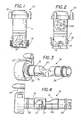
- inline dispersal valve 52 is similar to the inline dispersal valve 10 of Figures 1 and 2 .
- inline dispersal valve includes a molded one-piece cover 53 for enclosing the interior of a housing 54 of the inline dispersal valve 52.
- Inline dispersal valve 55 also includes a drain valve 56 (shown in Figure 16 ) and a bleed valve 57 (shown in Figure 17 ) for resolving dispersal issues.
- a drain valve 56 shown in Figure 16
- a bleed valve 57 shown in Figure 17
- an air pocket may be present in the housing 54. If the air pocket in the chamber in housing 54 is too large it hinders the dispensing of the dispersant supported within the chamber by preventing the fluids directed into the chamber from coming into contact with the dispersant located in the air pocket.
- Bleed valve 57 functions to alleviate the aforementioned problem by purging the trapped air pocket out from the chamber of the inline dispersal valve housing 52 to allow fluids directed in the chamber of inline dispersal valve housing 52 to come into contact with a majority of the dispersant supported therein.
- the elevation of bleed valve 57 is such that the air in the housing can be bled until the fluid level reaches the bleed valve 57. At this point the bleed valve 57 is closed leaving an air pocket above the level of the bleed valve 57.
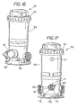
- Figure 18 shows a top view of a base 58 of the inline dispersal valve 52 of Figures 16 and 17 for removably supporting the inline dispersal valve housing 54 thereon.
- the base 58 of Figure 18 is shown having fastening regions 59 thereon for the securement of the inline dispersal valve housing 54 thereon via fasteners such as but not limited to bolts and screws.
- the base 58 of Figure 18 also includes a set of ears 60 located thereon for providing additional support and stability for the inline dispersal valve housing 54.
- a feature of the base 52 is that unlike the inline dispersal valve housing 54 which comprises a material having sufficient rigidity to handle the pressure requirements of the fluids and the fluid and dispersant mixtures therein, the base 52 of the inline dispersal valve 52 can comprise a material having less rigidity than the inline dispersal valve housing 54 to provide an enhance shock resistance support for the dispersal valve.
- FIG 19 shows an embodiment of a clip member 61 for lockingly securing a rotatable member such as a rotatable member 68 of Figures 16 and 17 to an inline dispenser housing.
- the clip member 61 comprises a clip body 62 having a first end 63 and a second end 64.
- the clip member 61 includes a clip head 65 located at the second end 63 of the clip body 62 and a resilient flange 66 branching from the clip body 62 and having a free end 67 expending in a direction towards the clip head 65.
- the clip head 65 includes a clip head surface 68 conforming to the shape of a surface of the rotatable member that the clip member 61 is lockingly engaging the rotatable member 18.
- the alternative embodiments can comprise a clip member having a resilient flange branching from different locations on the clip body
- the embodiment of Figure 19 shows the resilient flange 66 branching from proximal the first end 63 of the clip body 62.
- the free end 67 of the resilient flange 66 is located proximal the clip head 65 with a distance "d" between the free end 67 of the resilient flange 66 and surface 68 of the clip head 65 being sufficient to support a portion of a wall 69 of the rotatable member 68 (shown in Figure 17 ) therein.
- the distance "d" between the free end 67 of the resilient flange 66 and surface 68 of the clip head 65 should also be sufficient to allow for the first end 63 of the clip body 62 to extend through the second slot and lockingly remain thereat.
- the rotatable member 68 includes a first slot 70 and a second slot 71 located proximal an end 72 of rotatable member 68 with the first slot 70 and the second slot 71 positioned on the rotatable member 68 in a condition parallel to each other.
- the parallel positioning of the slots 70 and 71 enable the clip member 61 to simultaneously extend through both the first slot 70 and the second slot 71 of the rotatable member 68.
- the resilient flange 66 is moved towards the clip body 62 to displace the engagement of the free end 67 of the resilient flange 66 with the interior surface of the rotatable member 68 after which the clip member 61 can then be removed from the slots 70 and 71 of the rotatable member 68.
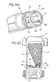
- Figure 20 shows a partial cross-sectional view of an alternative embodiment of an inline dispersal valve 73.
- Inline dispersal valve 73 comprises similar components as the inline dispersal valve 10 of Figures 1, 2 , 7, 8 , 9, 10 , 11, and 12 in that inline dispersal valve 73 includes a rotatable member 74 having a fluid deflecting surface (not shown) for directing a portion of a fluid stream through a chamber76 of a housing 75 of the inline dispersal valve 73.
- inline dispersal valve 73 is shown in Figure 20 as including the use of a removable canister 77 supported within chamber 76 of a housing 75 of inline dispersal valve 73 for supporting a dispersant 78 therein for dispensing into the fluid stream.
- the chamber 76 of inline dispersal valve 73 is shown as including a chamber inlet 81 for receiving fluids directed therethrough from the fluid stream and a chamber outlet 82 to provide a path for fluids located in the chamber 76 of the housing 75 to return back to the fluid stream.
- canister 77 includes a canister fluid inlet port 79 mateable with the chamber inlet 81 and a canister fluid outlet port 80.
- inline dispersal valve 73 In the operation of inline dispersal valve 73, a portion of the fluid stream is directed through chamber inlet 81 and into canister 77 where the fluids87. come into contact with the dispersant 78.
- the interaction between the fluids 87 and the dispersant results in a portion of the dispersant being dispensed or dissolve into the fluids 87 and is carried out of canister 77 and into the chamber 76 of the inline dispersal valve housing 75 via the canister fluid outlet port 80.
- the fluid containing the dispensed dispersant is then carried through the chamber outlet 82 into the fluid stream.
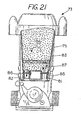
- Figure 21 is a partial cross-sectional view showing inline dispersal valve 73 supporting a removable canister 83 containing a dispersant 84 within chamber 76 of a housing 75.
- canister 83 as shown in Figure 21 includes a canister fluid inlet port 85 mateable with the chamber inlet 81. However, unlike canister 77, canister 83 also includes a canister outlet port 86mateable with the chamber outlet 82 of housing 75.
- inline dispersal valve 73 As shown in the embodiment of Figure 21 , a portion of the fluid stream 87 is directed through chamber inlet 81 and directly into canister 83 where the fluids 87 come into contact with the dispersant 84.
- the interaction between fluids 87 and dispersant 84 results in a portion of the dispersant 84 being dispensed or dissolved into the fluid 87.
- the fluids 87 along with the dispensed dispersants is eventually carried out of canister 83 via the canister fluid outlet port 80 and directly through chamber outlet 82 into the fluid stream.
- inline dispersal valve as disclosed above comprises various components all preferably form from a polymer plastic or the like.
Landscapes
- Chemical & Material Sciences (AREA)
- Chemical Kinetics & Catalysis (AREA)
- Engineering & Computer Science (AREA)
- Organic Chemistry (AREA)
- Hydrology & Water Resources (AREA)
- Life Sciences & Earth Sciences (AREA)
- Environmental & Geological Engineering (AREA)
- Water Supply & Treatment (AREA)
- Health & Medical Sciences (AREA)
- Medicinal Chemistry (AREA)
- Mechanical Engineering (AREA)
- Mechanically-Actuated Valves (AREA)
- Devices For Dispensing Beverages (AREA)
- Coating Apparatus (AREA)
- Indication Of The Valve Opening Or Closing Status (AREA)
- Closures For Containers (AREA)
Claims (10)
- Distributeur de matériaux d'épuration de l'eau, pour une piscine de natation ou analogue, comprenant :- un boîtier (11, 54, 75), pour recevoir un flux d'eau (37) et- une surface de déviation de fluide (20), susceptible d'être positionnée dans le flux d'eau (37) s'écoulant à travers un conduit (16) du boîtier (11, 54, 75), pour diriger une partie (38) du flux d'eau (37) dans une chambre (14, 76) du boîtier (11, 54, 75), caractérisé en ce que ladite surface de déviation de fluide (20) est également susceptible d'être positionnée hors du flux d'eau (37), de manière à bloquer l'écoulement d'eau dans la chambre (14, 76) du boîtier (11, 54, 75), dans lequel une condition d'écoulement d'eau non entravé à travers le conduit (16) est établie lorsque la surface de déviation de fluide (20) est déplacée hors d'une lumière (37, 36) du conduit (16).
- Distributeur de matériaux d'épuration de l'eau selon la revendication 1, comprenant en outre un organe rotatif (18), pour ouvrir et fermer un orifice à fluide (39) du distributeur, dans lequel un corps de l'organe rotatif (18) ayant une surface (19) cylindrique, s'accouplant et venant en prise avec un réceptacle (17) cylindrique du boîtier (11, 54, 75), pour former une mise en prise en rotation avec la chambre (14, 76), comprend la surface de déviation de fluide (20) et une poignée de levier (27), la poignée de levier (27) comprenant un pointeur, pour indiquer une position en rotation de la surface de déviation de fluide (20).
- Distributeur selon la revendication 2, dans lequel l'organe rotatif (18) présente un rayon de courbure sensiblement identique au rayon de courbure du conduit (16).
- Distributeur selon la revendication 1, le distributeur comprenant en outre :- un orifice à fluide (39) à taille variable, dans le boîtier (11, 54, 75) ;- un indicateur de taille d'orifice à fluide (30), l'indicateur de taille d'orifice à fluide (30) étant tourné vers le haut, de manière à être visible au-dessus du boîtier (11, 54, 75), pour permettre à un utilisateur de régler la taille de l'orifice à fluide tout en observant l'indicateur de taille d'orifice à fluide (30) à partir du dessus du boîtier (11, 54, 75).
- Distributeur selon la revendication 2 ou 3, dans lequel le distributeur est une soupape de dispersion (10, 73) installée en ligne, pour doser une quantité de matériau distribué dans un flux de fluide (37), le distributeur comprenant l'organe rotatif (18, 74) ayant une surface (19) cylindrique, s'accouplant avec un réceptacle (17) cylindrique du boîtier (11, 75), pour former une mise en prise en rotation avec la chambre (14, 76) du boîtier (11, 75), l'organe rotatif (18, 74) présentant la surface de déviation de fluide (20), la surface de déviation de fluide (20) obstruant au moins la partie (38) de l'écoulement de fluide (37) pour diriger des fluides, provenant de l'écoulement de fluide (37), à travers la chambre (14, 76) lorsque l'organe rotatif (18, 74) est en une position ouverte, pour permettre aux fluides dirigés de transporter le dispersant (15, 78) hors de la chambre (14, 76) et à les faire revenir dans un flux de fluide (36), la surface de déviation de fluide (20) étant située en un état hors du chemin, pour empêcher la diversion de fluides provenant du flux de fluide (37) à travers la chambre (14, 76) et retour dans le flux de fluide (36), lorsque l'organe rotatif (18, 74) est en une position fermée, l'organe rotatif (18, 74) étant déplaçable entre la position ouverte et la position fermée, de manière à permettre d'obtenir une commande de l'organe rotatif (18, 74) à fournir pour la partie (38) du fluide (37), dans lequel la partie (38) est proportionnelle à la position de l'organe rotatif (18, 74), entre la position complètement ouverte et la position complètement fermée.
- Distributeur selon l'une ou plusieurs des revendications précédentes, dans lequel, pour l'ajustement instantané d'une poche de gaz dans le distributeur, le boîtier (54) présente une chambre (14) fermée, pour distribuer un matériau de conditionnement de l'eau (15) par le biais du contact avec l'eau avec le matériau de conditionnement de l'eau (15) situé au moins partiellement dans la poche de gaz ;
et dans lequel le distributeur comprend une soupape de purge (57) située dans le boîtier (54), à un niveau suffisant pour diminuer la taille de la poche de gaz, à une valeur permettant d'établir on contact avec l'eau amélioré avec les matériaux de conditionnement de l'eau se trouvant dans la chambre fermée. - Distributeur selon la revendication 2, 3 ou 5, comprenant en outre une attache (61) pour assurer par verrouillage l'organe rotatif (18, 68), pour ouvrir et fermer l'orifice à fluide (39) du boîtier de distributeur (11, 54, 75) installé en ligne, l'attache (61) comprenant :- un corps d'attache (62), ayant une première extrémité (63) et une deuxième extrémité (64) ;- une tête d'attache (65), située à la deuxième extrémité (64) du corps d'attache (62) ; et- un rebord (66) élastique, se ramifiant à partir du corps d'attache (62) et ayant une extrémité libre s'étendant vers la tête d'attache (65).
- Distributeur selon l'une ou plusieurs des revendications précédentes, comprenant en outre un couvercle de distributeur (40), dans lequel le couvercle de distributeur (40) comprend :- un chapeau (41);- un autre boîtier (42), susceptible de tourner par rapport au chapeau (41) ; et- un jeu de poignées (50) faisant saillie radialement, s'étendant à partir du boîtier (42), pour permettre à l'utilisateur de placer le chapeau (41) en et hors de prise, par rotation du boîtier (42).
- Distributeur selon l'une ou plusieurs des revendications 1 à 7 précédentes, comprenant en outrun couvercle de distributeur (40), dans lequel le couvercle de distributeur (40) comprend :- un chapeau (41) comprenant une région de siège (44) ;- un autre boîtier (42), retenu axialement mais susceptible de tourner par rapport au chapeau (41), de manière à placer la région de siège (44) en et hors de prise assurant la fonction de siège, sans rotation du chapeau (41).
- Distributeur selon l'une ou plusieurs des revendications précédentes, dans lequel le distributeur, qui est une soupape de dispersion (73), comprend en outre un récipient métallique (77) situé à l'intérieur de la chambre (76) du boîtier (75), le récipient métallique (77) étant prévu pour supporter en son sein un dispersant (78), prévu pour distribution dans le flux de fluide (87).
Applications Claiming Priority (2)
| Application Number | Priority Date | Filing Date | Title |
|---|---|---|---|
| US11/128,124 US7604018B2 (en) | 2005-05-12 | 2005-05-12 | Dispensers |
| PCT/US2006/016160 WO2006124233A2 (fr) | 2005-05-12 | 2006-04-27 | Distributeur |
Publications (3)
| Publication Number | Publication Date |
|---|---|
| EP1886200A2 EP1886200A2 (fr) | 2008-02-13 |
| EP1886200A4 EP1886200A4 (fr) | 2010-03-24 |
| EP1886200B1 true EP1886200B1 (fr) | 2011-11-30 |
Family
ID=37417945
Family Applications (1)
| Application Number | Title | Priority Date | Filing Date |
|---|---|---|---|
| EP06751725A Expired - Lifetime EP1886200B1 (fr) | 2005-05-12 | 2006-04-27 | Distributeur |
Country Status (5)
| Country | Link |
|---|---|
| US (6) | US7604018B2 (fr) |
| EP (1) | EP1886200B1 (fr) |
| AT (1) | ATE535301T1 (fr) |
| CA (1) | CA2605501A1 (fr) |
| WO (1) | WO2006124233A2 (fr) |
Families Citing this family (28)
| Publication number | Priority date | Publication date | Assignee | Title |
|---|---|---|---|---|
| US9960300B2 (en) * | 2007-11-21 | 2018-05-01 | Arkema Inc. | Photovoltaic module using PVDF based flexible glazing film |
| CA2760632A1 (fr) * | 2009-06-10 | 2010-12-16 | Zodiac Pool Care Europe | Dispositifs permettant de traiter, de detecter ou d'agir autrement sur un fluide |
| AU330145S (en) * | 2010-01-29 | 2010-03-31 | Evolve Supply Chain Pty Ltd | Electrolytic cell |
| EP2903675B1 (fr) * | 2012-10-02 | 2018-08-01 | Koninklijke Philips N.V. | Coussin personnalisable utilisant des inserts enfichables |
| US9260328B2 (en) * | 2013-11-13 | 2016-02-16 | Axiall Ohio, Inc. | Chemical feeder |
| US9540265B2 (en) | 2014-04-04 | 2017-01-10 | Axiall Ohio, Inc. | Chemical feeder |
| DE202015007200U1 (de) | 2014-04-10 | 2016-01-13 | Unger Marketing International, Llc | Reinwassersysteme |
| USD740915S1 (en) | 2014-04-10 | 2015-10-13 | Unger Marketing International, Llc | Water purification device |
| US11911720B2 (en) | 2014-04-10 | 2024-02-27 | Unger Marketing International, Llc | Fluid purification device |
| USD742997S1 (en) | 2014-04-10 | 2015-11-10 | Unger Marketing International, Llc | Water purification media device |
| US9272249B2 (en) * | 2014-05-14 | 2016-03-01 | Axiall Ohio, Inc. | Chemical feeder |
| CA2953181C (fr) | 2014-07-15 | 2022-07-19 | Axiall Ohio, Inc. | Mecanisme alimentateur de produit chimique comportant une cartouche tubulaire avec un solide soluble |
| US9725920B2 (en) | 2014-07-16 | 2017-08-08 | King Technology Inc. | Dispensing systems |
| US20170370482A1 (en) * | 2015-01-15 | 2017-12-28 | Axon Energy Products Uk Ltd | Sub-plate mounted valve |
| USD820709S1 (en) * | 2015-04-01 | 2018-06-19 | Xtralis Global | Flange of a sampling point assembly |
| US11154800B2 (en) | 2015-04-10 | 2021-10-26 | Unger Marketing International, Llc | Fluid purification device |
| USD849886S1 (en) | 2017-08-28 | 2019-05-28 | Unger Marketing International, Llc | Water purification device |
| US11148082B2 (en) | 2015-04-10 | 2021-10-19 | Unger Marketing International, Llc | Fluid purification device |
| US10286365B2 (en) | 2016-02-01 | 2019-05-14 | King Technology Inc | Dispensing system for cakeable materials |
| USD907742S1 (en) | 2018-03-07 | 2021-01-12 | Unger Marketing International, Llc | Water purification media device |
| US11203539B1 (en) | 2018-09-17 | 2021-12-21 | King Technology Inc | Free chlorine maintained systems |
| USD958928S1 (en) | 2018-11-01 | 2022-07-26 | Unger Marketing International, Llc | Water purification media device |
| WO2021097188A1 (fr) | 2019-11-15 | 2021-05-20 | Sundance Spas, Inc. | Systèmes et dispositifs d'analyse d'eau |
| US12029149B2 (en) * | 2021-04-22 | 2024-07-09 | The Toro Company | Plant feeding device for use with drip irrigation |
| CN113603202B (zh) * | 2021-08-12 | 2025-04-08 | 广东大任生物科技有限责任公司 | 一种碳酸泉制备装置 |
| CN118234684A (zh) | 2021-09-14 | 2024-06-21 | 科阴科技公司 | 直列式分配系统 |
| USD1066565S1 (en) * | 2023-07-13 | 2025-03-11 | Spin S.A. de C.V. | Chlorine tab dispenser |
| WO2025230815A1 (fr) | 2024-04-29 | 2025-11-06 | King Technology, Inc. | Systèmes exempts de chlore libre |
Family Cites Families (20)
| Publication number | Priority date | Publication date | Assignee | Title |
|---|---|---|---|---|
| US1740879A (en) * | 1929-12-24 | sonner | ||
| US2536361A (en) | 1946-03-11 | 1951-01-02 | Austin P Flanders | Plant food feeder |
| US2521802A (en) * | 1947-05-16 | 1950-09-12 | Hagan Corp | Feeding device |
| US2604446A (en) | 1949-09-19 | 1952-07-22 | Bruner Corp | Water conditioning device |
| US2989979A (en) * | 1957-11-06 | 1961-06-27 | Wesley N Karlson | Chemical feeders |
| US3003518A (en) * | 1958-04-07 | 1961-10-10 | Tisdale Larry | Faucet suds dispenser |
| US3899425A (en) * | 1972-08-28 | 1975-08-12 | H S M Americas Ltd | Modular filter and automatic chlorinator for swimming pools |
| US4662387A (en) * | 1985-10-03 | 1987-05-05 | King Lloyd H Sr | Inline dispersal valve |
| US5076315A (en) * | 1990-07-23 | 1991-12-31 | King Joseph A | Dispersal valve and canister |
| US5404594A (en) * | 1993-04-05 | 1995-04-11 | Ring; Russel F. | In-line toilet bowl cleaner apparatus |
| US5660802A (en) * | 1994-06-07 | 1997-08-26 | Fountainhead Technologies, Inc. | Water purifier |
| CA2144099C (fr) * | 1994-12-07 | 2004-10-19 | Donald P. Shoemaker | Distributeur de liquide |
| US5624559A (en) * | 1995-10-27 | 1997-04-29 | H-Tech, Inc. | Bag filter and retainer therefor |
| US5932093A (en) * | 1998-01-30 | 1999-08-03 | Chulick; Joe | Chlorine dispenser |
| US6803237B2 (en) * | 2000-01-25 | 2004-10-12 | Woods Hole Oceanographic Institution | Sequential processing reaction vessel for chemical fractionation and analysis |
| IE20000110A1 (en) * | 2000-02-07 | 2001-08-22 | Loctite R & D Ltd | Applicator, Applicator Cap and a Container Having an Applicator Cap |
| US6419166B1 (en) * | 2000-04-28 | 2002-07-16 | Stan F. Brzezinski | Dispenser to liquid stream |
| AR028746A1 (es) * | 2000-06-23 | 2003-05-21 | Norton Health Care Ltd | Cartucho de dosis previamente medidas para inhalador de polvo seco accionado por la respiracion, el inhalador y un metodo de provision de dosis previamente medidas de polvo seco |
| US6497250B1 (en) * | 2001-07-05 | 2002-12-24 | Praher Canada Products Ltd. | Multi passage valve |
| US6811047B1 (en) * | 2003-04-14 | 2004-11-02 | Seaquist Closures Foreign, Inc. | Closure with enhanced removal capability |
-
2005
- 2005-05-12 US US11/128,124 patent/US7604018B2/en active Active
-
2006
- 2006-04-27 CA CA002605501A patent/CA2605501A1/fr not_active Abandoned
- 2006-04-27 EP EP06751725A patent/EP1886200B1/fr not_active Expired - Lifetime
- 2006-04-27 AT AT06751725T patent/ATE535301T1/de active
- 2006-04-27 WO PCT/US2006/016160 patent/WO2006124233A2/fr not_active Ceased
-
2009
- 2009-09-08 US US12/584,554 patent/US8464743B2/en not_active Expired - Lifetime
-
2013
- 2013-02-12 US US13/815,231 patent/US8757188B2/en not_active Expired - Lifetime
-
2014
- 2014-03-18 US US13/999,727 patent/US9493276B2/en not_active Expired - Lifetime
-
2016
- 2016-08-23 US US15/330,215 patent/US10781016B2/en not_active Expired - Lifetime
-
2019
- 2019-01-31 US US16/350,904 patent/US11414243B2/en active Active
Also Published As
| Publication number | Publication date |
|---|---|
| US8757188B2 (en) | 2014-06-24 |
| US20140299635A1 (en) | 2014-10-09 |
| US9493276B2 (en) | 2016-11-15 |
| US11414243B2 (en) | 2022-08-16 |
| WO2006124233A3 (fr) | 2009-05-28 |
| US7604018B2 (en) | 2009-10-20 |
| US10781016B2 (en) | 2020-09-22 |
| EP1886200A4 (fr) | 2010-03-24 |
| US20100000610A1 (en) | 2010-01-07 |
| US8464743B2 (en) | 2013-06-18 |
| ATE535301T1 (de) | 2011-12-15 |
| CA2605501A1 (fr) | 2006-11-23 |
| US20130327786A1 (en) | 2013-12-12 |
| WO2006124233A2 (fr) | 2006-11-23 |
| US20170015472A1 (en) | 2017-01-19 |
| US20190168922A1 (en) | 2019-06-06 |
| US20060254646A1 (en) | 2006-11-16 |
| EP1886200A2 (fr) | 2008-02-13 |
Similar Documents
| Publication | Publication Date | Title |
|---|---|---|
| EP1886200B1 (fr) | Distributeur | |
| CN101932862B (zh) | 阀门组件 | |
| US6908551B2 (en) | Combination inline dispenser and non-fitted cartridge | |
| JPH03502725A (ja) | 温度および水量制御弁組立体 | |
| EP3109521B1 (fr) | Ensemble de boîtier de soupape de robinet | |
| US5655563A (en) | Dispensing apparatus with line pressure diverter | |
| JP2002513125A (ja) | バイパス弁 | |
| KR20100043543A (ko) | 수도밸브 | |
| KR20170050576A (ko) | 유로전환밸브 및 이를 구비한 수처리장치 | |
| EP2917419B1 (fr) | Poignée de robinet comportant une cartouche d'obturateur parallèle à une surface de montage | |
| US5738135A (en) | Dispensing apparatus with line pressure diverter | |
| KR20030032051A (ko) | 위생 피팅용 카트리지 | |
| US7334604B1 (en) | Faucet having multiple different water outlet manners | |
| US4306582A (en) | Mixing valve | |
| US8220671B2 (en) | Lubricant dispenser with nozzle | |
| KR200274150Y1 (ko) | 배출방향 조정이 가능한 콕 밸브 | |
| EP3971350B1 (fr) | Un robinet pour une vanne de remplissage d'un reservoir de chasse d'appareil sanitaire | |
| US4397329A (en) | Mixing valve | |
| KR100467140B1 (ko) | 하프 볼 밸브 | |
| AU2004100412A4 (en) | Diverter | |
| KR890002711Y1 (ko) | 정수기를 갖춘 수도꼭지용 어댑터 | |
| JPH0712770Y2 (ja) | 多方弁 | |
| AU2002100069A4 (en) | A diverter valve | |
| CA2665233C (fr) | Distributeur de lubrifiant avec buse | |
| GB2314115A (en) | Water diversion valve |
Legal Events
| Date | Code | Title | Description |
|---|---|---|---|
| PUAI | Public reference made under article 153(3) epc to a published international application that has entered the european phase |
Free format text: ORIGINAL CODE: 0009012 |
|
| 17P | Request for examination filed |
Effective date: 20071212 |
|
| AK | Designated contracting states |
Kind code of ref document: A2 Designated state(s): AT BE BG CH CY CZ DE DK EE ES FI FR GB GR HU IE IS IT LI LT LU LV MC NL PL PT RO SE SI SK TR |
|
| AX | Request for extension of the european patent |
Extension state: AL BA HR MK YU |
|
| DAX | Request for extension of the european patent (deleted) | ||
| R17D | Deferred search report published (corrected) |
Effective date: 20090528 |
|
| A4 | Supplementary search report drawn up and despatched |
Effective date: 20100219 |
|
| RIC1 | Information provided on ipc code assigned before grant |
Ipc: C02F 1/68 20060101ALI20100215BHEP Ipc: B01F 5/04 20060101ALI20100215BHEP Ipc: B01F 1/00 20060101AFI20100215BHEP |
|
| 17Q | First examination report despatched |
Effective date: 20100512 |
|
| REG | Reference to a national code |
Ref country code: DE Ref legal event code: R079 Ref document number: 602006026169 Country of ref document: DE Free format text: PREVIOUS MAIN CLASS: G05D0007000000 Ipc: B01F0001000000 |
|
| GRAP | Despatch of communication of intention to grant a patent |
Free format text: ORIGINAL CODE: EPIDOSNIGR1 |
|
| RIC1 | Information provided on ipc code assigned before grant |
Ipc: C02F 1/68 20060101ALI20110520BHEP Ipc: B01F 5/04 20060101ALI20110520BHEP Ipc: B01F 1/00 20060101AFI20110520BHEP |
|
| RIN1 | Information on inventor provided before grant (corrected) |
Inventor name: WILLIAMS, RANDY Inventor name: JOHNSON, JEFFREY Inventor name: SCHOMBURG, KENNETH, V. Inventor name: SNETTING, MARK Inventor name: KING, JOSEPH, A. |
|
| GRAS | Grant fee paid |
Free format text: ORIGINAL CODE: EPIDOSNIGR3 |
|
| GRAA | (expected) grant |
Free format text: ORIGINAL CODE: 0009210 |
|
| AK | Designated contracting states |
Kind code of ref document: B1 Designated state(s): AT BE BG CH CY CZ DE DK EE ES FI FR GB GR HU IE IS IT LI LT LU LV MC NL PL PT RO SE SI SK TR |
|
| REG | Reference to a national code |
Ref country code: GB Ref legal event code: FG4D Ref country code: CH Ref legal event code: EP |
|
| REG | Reference to a national code |
Ref country code: IE Ref legal event code: FG4D |
|
| REG | Reference to a national code |
Ref country code: DE Ref legal event code: R096 Ref document number: 602006026169 Country of ref document: DE Effective date: 20120308 |
|
| REG | Reference to a national code |
Ref country code: NL Ref legal event code: VDEP Effective date: 20111130 |
|
| LTIE | Lt: invalidation of european patent or patent extension |
Effective date: 20111130 |
|
| PG25 | Lapsed in a contracting state [announced via postgrant information from national office to epo] |
Ref country code: LT Free format text: LAPSE BECAUSE OF FAILURE TO SUBMIT A TRANSLATION OF THE DESCRIPTION OR TO PAY THE FEE WITHIN THE PRESCRIBED TIME-LIMIT Effective date: 20111130 Ref country code: IS Free format text: LAPSE BECAUSE OF FAILURE TO SUBMIT A TRANSLATION OF THE DESCRIPTION OR TO PAY THE FEE WITHIN THE PRESCRIBED TIME-LIMIT Effective date: 20120330 |
|
| PG25 | Lapsed in a contracting state [announced via postgrant information from national office to epo] |
Ref country code: BE Free format text: LAPSE BECAUSE OF FAILURE TO SUBMIT A TRANSLATION OF THE DESCRIPTION OR TO PAY THE FEE WITHIN THE PRESCRIBED TIME-LIMIT Effective date: 20111130 Ref country code: PT Free format text: LAPSE BECAUSE OF FAILURE TO SUBMIT A TRANSLATION OF THE DESCRIPTION OR TO PAY THE FEE WITHIN THE PRESCRIBED TIME-LIMIT Effective date: 20120330 Ref country code: GR Free format text: LAPSE BECAUSE OF FAILURE TO SUBMIT A TRANSLATION OF THE DESCRIPTION OR TO PAY THE FEE WITHIN THE PRESCRIBED TIME-LIMIT Effective date: 20120301 Ref country code: LV Free format text: LAPSE BECAUSE OF FAILURE TO SUBMIT A TRANSLATION OF THE DESCRIPTION OR TO PAY THE FEE WITHIN THE PRESCRIBED TIME-LIMIT Effective date: 20111130 Ref country code: NL Free format text: LAPSE BECAUSE OF FAILURE TO SUBMIT A TRANSLATION OF THE DESCRIPTION OR TO PAY THE FEE WITHIN THE PRESCRIBED TIME-LIMIT Effective date: 20111130 Ref country code: SE Free format text: LAPSE BECAUSE OF FAILURE TO SUBMIT A TRANSLATION OF THE DESCRIPTION OR TO PAY THE FEE WITHIN THE PRESCRIBED TIME-LIMIT Effective date: 20111130 Ref country code: SI Free format text: LAPSE BECAUSE OF FAILURE TO SUBMIT A TRANSLATION OF THE DESCRIPTION OR TO PAY THE FEE WITHIN THE PRESCRIBED TIME-LIMIT Effective date: 20111130 |
|
| PG25 | Lapsed in a contracting state [announced via postgrant information from national office to epo] |
Ref country code: CY Free format text: LAPSE BECAUSE OF FAILURE TO SUBMIT A TRANSLATION OF THE DESCRIPTION OR TO PAY THE FEE WITHIN THE PRESCRIBED TIME-LIMIT Effective date: 20111130 |
|
| PG25 | Lapsed in a contracting state [announced via postgrant information from national office to epo] |
Ref country code: DK Free format text: LAPSE BECAUSE OF FAILURE TO SUBMIT A TRANSLATION OF THE DESCRIPTION OR TO PAY THE FEE WITHIN THE PRESCRIBED TIME-LIMIT Effective date: 20111130 Ref country code: BG Free format text: LAPSE BECAUSE OF FAILURE TO SUBMIT A TRANSLATION OF THE DESCRIPTION OR TO PAY THE FEE WITHIN THE PRESCRIBED TIME-LIMIT Effective date: 20120229 Ref country code: SK Free format text: LAPSE BECAUSE OF FAILURE TO SUBMIT A TRANSLATION OF THE DESCRIPTION OR TO PAY THE FEE WITHIN THE PRESCRIBED TIME-LIMIT Effective date: 20111130 Ref country code: EE Free format text: LAPSE BECAUSE OF FAILURE TO SUBMIT A TRANSLATION OF THE DESCRIPTION OR TO PAY THE FEE WITHIN THE PRESCRIBED TIME-LIMIT Effective date: 20111130 Ref country code: CZ Free format text: LAPSE BECAUSE OF FAILURE TO SUBMIT A TRANSLATION OF THE DESCRIPTION OR TO PAY THE FEE WITHIN THE PRESCRIBED TIME-LIMIT Effective date: 20111130 |
|
| PG25 | Lapsed in a contracting state [announced via postgrant information from national office to epo] |
Ref country code: RO Free format text: LAPSE BECAUSE OF FAILURE TO SUBMIT A TRANSLATION OF THE DESCRIPTION OR TO PAY THE FEE WITHIN THE PRESCRIBED TIME-LIMIT Effective date: 20111130 Ref country code: IT Free format text: LAPSE BECAUSE OF FAILURE TO SUBMIT A TRANSLATION OF THE DESCRIPTION OR TO PAY THE FEE WITHIN THE PRESCRIBED TIME-LIMIT Effective date: 20111130 Ref country code: PL Free format text: LAPSE BECAUSE OF FAILURE TO SUBMIT A TRANSLATION OF THE DESCRIPTION OR TO PAY THE FEE WITHIN THE PRESCRIBED TIME-LIMIT Effective date: 20111130 |
|
| REG | Reference to a national code |
Ref country code: AT Ref legal event code: MK05 Ref document number: 535301 Country of ref document: AT Kind code of ref document: T Effective date: 20111130 |
|
| PLBE | No opposition filed within time limit |
Free format text: ORIGINAL CODE: 0009261 |
|
| STAA | Information on the status of an ep patent application or granted ep patent |
Free format text: STATUS: NO OPPOSITION FILED WITHIN TIME LIMIT |
|
| REG | Reference to a national code |
Ref country code: DE Ref legal event code: R119 Ref document number: 602006026169 Country of ref document: DE |
|
| 26N | No opposition filed |
Effective date: 20120831 |
|
| PG25 | Lapsed in a contracting state [announced via postgrant information from national office to epo] |
Ref country code: MC Free format text: LAPSE BECAUSE OF NON-PAYMENT OF DUE FEES Effective date: 20120430 |
|
| REG | Reference to a national code |
Ref country code: CH Ref legal event code: PL |
|
| GBPC | Gb: european patent ceased through non-payment of renewal fee |
Effective date: 20120427 |
|
| REG | Reference to a national code |
Ref country code: DE Ref legal event code: R097 Ref document number: 602006026169 Country of ref document: DE Effective date: 20120831 |
|
| PG25 | Lapsed in a contracting state [announced via postgrant information from national office to epo] |
Ref country code: AT Free format text: LAPSE BECAUSE OF FAILURE TO SUBMIT A TRANSLATION OF THE DESCRIPTION OR TO PAY THE FEE WITHIN THE PRESCRIBED TIME-LIMIT Effective date: 20111130 Ref country code: CH Free format text: LAPSE BECAUSE OF NON-PAYMENT OF DUE FEES Effective date: 20120430 Ref country code: GB Free format text: LAPSE BECAUSE OF NON-PAYMENT OF DUE FEES Effective date: 20120427 Ref country code: LI Free format text: LAPSE BECAUSE OF NON-PAYMENT OF DUE FEES Effective date: 20120430 |
|
| REG | Reference to a national code |
Ref country code: DE Ref legal event code: R119 Ref document number: 602006026169 Country of ref document: DE Effective date: 20121101 |
|
| PG25 | Lapsed in a contracting state [announced via postgrant information from national office to epo] |
Ref country code: IE Free format text: LAPSE BECAUSE OF NON-PAYMENT OF DUE FEES Effective date: 20120427 Ref country code: ES Free format text: LAPSE BECAUSE OF FAILURE TO SUBMIT A TRANSLATION OF THE DESCRIPTION OR TO PAY THE FEE WITHIN THE PRESCRIBED TIME-LIMIT Effective date: 20120311 |
|
| PG25 | Lapsed in a contracting state [announced via postgrant information from national office to epo] |
Ref country code: FI Free format text: LAPSE BECAUSE OF FAILURE TO SUBMIT A TRANSLATION OF THE DESCRIPTION OR TO PAY THE FEE WITHIN THE PRESCRIBED TIME-LIMIT Effective date: 20111130 |
|
| PG25 | Lapsed in a contracting state [announced via postgrant information from national office to epo] |
Ref country code: TR Free format text: LAPSE BECAUSE OF FAILURE TO SUBMIT A TRANSLATION OF THE DESCRIPTION OR TO PAY THE FEE WITHIN THE PRESCRIBED TIME-LIMIT Effective date: 20111130 |
|
| PG25 | Lapsed in a contracting state [announced via postgrant information from national office to epo] |
Ref country code: LU Free format text: LAPSE BECAUSE OF NON-PAYMENT OF DUE FEES Effective date: 20120427 |
|
| PG25 | Lapsed in a contracting state [announced via postgrant information from national office to epo] |
Ref country code: HU Free format text: LAPSE BECAUSE OF FAILURE TO SUBMIT A TRANSLATION OF THE DESCRIPTION OR TO PAY THE FEE WITHIN THE PRESCRIBED TIME-LIMIT Effective date: 20060427 |
|
| PGFP | Annual fee paid to national office [announced via postgrant information from national office to epo] |
Ref country code: FR Payment date: 20140430 Year of fee payment: 9 |
|
| PG25 | Lapsed in a contracting state [announced via postgrant information from national office to epo] |
Ref country code: DE Free format text: LAPSE BECAUSE OF FAILURE TO SUBMIT A TRANSLATION OF THE DESCRIPTION OR TO PAY THE FEE WITHIN THE PRESCRIBED TIME-LIMIT Effective date: 20121101 |
|
| REG | Reference to a national code |
Ref country code: FR Ref legal event code: ST Effective date: 20151231 |
|
| PG25 | Lapsed in a contracting state [announced via postgrant information from national office to epo] |
Ref country code: FR Free format text: LAPSE BECAUSE OF NON-PAYMENT OF DUE FEES Effective date: 20150430 |