EP1886558B1 - Rolle für das Fliegenfischen - Google Patents
Rolle für das Fliegenfischen Download PDFInfo
- Publication number
- EP1886558B1 EP1886558B1 EP07380225A EP07380225A EP1886558B1 EP 1886558 B1 EP1886558 B1 EP 1886558B1 EP 07380225 A EP07380225 A EP 07380225A EP 07380225 A EP07380225 A EP 07380225A EP 1886558 B1 EP1886558 B1 EP 1886558B1
- Authority
- EP
- European Patent Office
- Prior art keywords
- brake
- pinion
- line
- spool
- gearing
- Prior art date
- Legal status (The legal status is an assumption and is not a legal conclusion. Google has not performed a legal analysis and makes no representation as to the accuracy of the status listed.)
- Active
Links
- 230000007246 mechanism Effects 0.000 claims abstract description 36
- 230000001105 regulatory effect Effects 0.000 claims abstract description 18
- 238000011084 recovery Methods 0.000 claims description 4
- 238000004804 winding Methods 0.000 claims description 2
- 241000251468 Actinopterygii Species 0.000 description 36
- 235000019688 fish Nutrition 0.000 description 36
- 238000000034 method Methods 0.000 description 14
- 230000009471 action Effects 0.000 description 13
- 238000005266 casting Methods 0.000 description 13
- 241000276420 Lophius piscatorius Species 0.000 description 10
- 230000000903 blocking effect Effects 0.000 description 8
- 239000004429 Calibre Substances 0.000 description 5
- 230000008901 benefit Effects 0.000 description 5
- XLYOFNOQVPJJNP-UHFFFAOYSA-N water Substances O XLYOFNOQVPJJNP-UHFFFAOYSA-N 0.000 description 5
- 241000819999 Nymphes Species 0.000 description 4
- 230000003446 memory effect Effects 0.000 description 4
- 230000003213 activating effect Effects 0.000 description 3
- 230000000694 effects Effects 0.000 description 3
- 230000006870 function Effects 0.000 description 3
- 238000005096 rolling process Methods 0.000 description 3
- 238000013461 design Methods 0.000 description 2
- 238000007667 floating Methods 0.000 description 2
- 230000006872 improvement Effects 0.000 description 2
- 244000062645 predators Species 0.000 description 2
- 238000003825 pressing Methods 0.000 description 2
- 241000972773 Aulopiformes Species 0.000 description 1
- 241000277331 Salmonidae Species 0.000 description 1
- 238000004873 anchoring Methods 0.000 description 1
- 230000005540 biological transmission Effects 0.000 description 1
- 230000001627 detrimental effect Effects 0.000 description 1
- 238000011161 development Methods 0.000 description 1
- 238000009826 distribution Methods 0.000 description 1
- 230000008569 process Effects 0.000 description 1
- 230000003252 repetitive effect Effects 0.000 description 1
- 235000019515 salmon Nutrition 0.000 description 1
- 238000010561 standard procedure Methods 0.000 description 1
- 238000012546 transfer Methods 0.000 description 1
Images


Classifications
-
- A—HUMAN NECESSITIES
- A01—AGRICULTURE; FORESTRY; ANIMAL HUSBANDRY; HUNTING; TRAPPING; FISHING
- A01K—ANIMAL HUSBANDRY; AVICULTURE; APICULTURE; PISCICULTURE; FISHING; REARING OR BREEDING ANIMALS, NOT OTHERWISE PROVIDED FOR; NEW BREEDS OF ANIMALS
- A01K89/00—Reels
- A01K89/02—Brake devices for reels
- A01K89/033—Brake devices for reels with a rotary drum, i.e. for reels with a rotating spool
- A01K89/05—Brakes connected to the spool by one-way clutch
-
- A—HUMAN NECESSITIES
- A01—AGRICULTURE; FORESTRY; ANIMAL HUSBANDRY; HUNTING; TRAPPING; FISHING
- A01K—ANIMAL HUSBANDRY; AVICULTURE; APICULTURE; PISCICULTURE; FISHING; REARING OR BREEDING ANIMALS, NOT OTHERWISE PROVIDED FOR; NEW BREEDS OF ANIMALS
- A01K89/00—Reels
- A01K89/015—Reels with a rotary drum, i.e. with a rotating spool
- A01K89/016—Fly reels, i.e. with a stub shaft support
-
- A—HUMAN NECESSITIES
- A01—AGRICULTURE; FORESTRY; ANIMAL HUSBANDRY; HUNTING; TRAPPING; FISHING
- A01K—ANIMAL HUSBANDRY; AVICULTURE; APICULTURE; PISCICULTURE; FISHING; REARING OR BREEDING ANIMALS, NOT OTHERWISE PROVIDED FOR; NEW BREEDS OF ANIMALS
- A01K89/00—Reels
- A01K89/02—Brake devices for reels
- A01K89/033—Brake devices for reels with a rotary drum, i.e. for reels with a rotating spool
Definitions
- the invention relates to a fly fishing reel comprising a housing, a main axis, a swivel driving lever, elastic recovery means for the lever rest position, a first pinion driven by the driving lever, said first pinion being provided coaxially to the main axis, a line wind up spool, provided coaxially to the main axis and a spool brake.
- the manual reel consists of a spool that can wind up the line mounted on an axis provided with in housing that is attached to the rod.
- the spool has a handle that allows it to be activated in a circular movement around the axis in the housing in order to retrieve the line.
- This type of reel does not have a gearing, whereby line retrieval is relatively slow.
- fly fishing the line is not simply a fishing line wound on the reel. It has at least two parts. At the end of the bait there is a transparent line a few centimeters long called leader, after this a special fly fishing line is tied, known as a fly line, which is characterised by its flexibility.
- the fly line is not usually very long because of the space it takes up in the spool, so if an extra length of line is needed, an additional line known by its English name, backing, is usually tied to the opposite end of the fly line.
- manual reels have an adjustable tension spool brake provided between the drum and the spool proper.
- the main function of the brake is to offer resistance to line feed-out when the fish pulls on the hook.
- the brake also helps to stop the line from coming out of the spool in an uncontrolled manner during casting, which would increase the risk of tangling the line.
- One of the drawbacks of the brake in manual reels is that if it is desired to retrieve the catch by activating the handle, the spool is activated directly by the handle.
- Another additional problem is that when retrieving the line, the brake offers added resistance to the strength of the current and the pulling force of the fish, which requires an additional effort by the angler. This means that if the handle is used to retrieve the line, the risk of losing the catch is high, because the brake cannot compensate the possible whipping action produced by the fish.
- the brake tension In its double function, the brake tension must be regulated optimally. On the one hand it is desirable that, when casting, the brake acts as gently as possible, in other words that the brake be adjusted to a reduced level of tension. On the other hand, when the fish strikes, it is desirable that the brake withstands the force of the fish insofar as it is possible, without breaking the leader. When the tension produced in the leader by the force of the fish is too high, the brake yields. If the level of brake tension is adjusted to the casting, the brake tends to slip excessively when the fish struggles, which does not help when wrestling against the fish to tire it more quickly. If, on the contrary, the braking tension is adjusted to the maximum tension permissible by the leader, the force needed to feed-out the line during casting is considerably increased, which is tiring and also a disadvantage with respect to reaching a considerable casting distance.
- Document FR-A-2 855 371 discloses a semi-automatic fly fishing reel comprising a housing with attaching means to attach the reel to a fishing rod, a spool rotatably mounted on a longitudinal central axis and a swivel lever provided with a gearing sector that meshes with a pinion which is also mounted on the said longitudinal central axis. Between the pinion and the spool, the reel further comprises a gearing, such that the lever can transmit its movement to the spool via the gearing.
- the calibre of the fly line depends mainly on the fly fishing technique to be used.
- Fly fishing has developed considerably in recent years. Initially, the "dry fly” fishing method was used, which consisted in fishing with a single, floating fly. In this case it is important to delicately land the fly on the water surface so as not to alert the fish, and so the fly lines used have a 1 mm calibre approximately. For this technique, the leader used is even finer, and frequently calibres of less than 0.1 mm are used.
- Another current technique is fishing with a "dropper fly", which is similar to the dry fly technique, but which uses more than one fly simultaneously.
- the third standard technique is the nymph fly fishing, which is applied to all water types.
- the bait are loaded with a small drag so that they do not float on the surface, and instead move with the deep currents.
- the leader and the fly line are coarser.
- the leader for nymph fly fishing can vary between 0.14 and 0.18 mm.
- another usual technique is the so-called streamer fly fishing technique, where a small fish imitation is used to feed predator species.
- the streamers are also loaded, so coarser lines are needed with leaders that vary between 0.2 and 0.22 mm.
- fly fishing is particularly appropriate for catching salmonidae. Its natural habitat is mountain rivers with strong currents, lakes or the sea, and this type of predator fish is characterised by its great strength, speed and craftiness. When fishing salmon with flies, in many situations the line has to be retrieved very quickly. Semi-automatic fly fishing reels do not always manage to retrieve the line in a semi-automatic manner at the necessary speed, and so the risk of losing the catch is very high.
- fly fishing casting consists of a repetitive whip movement whereby distance is gained as the line is fed out manually from the reel. This movement in itself is fairly tiring. Therefore, it is important that fly fishing reels are particularly lightweight.
- the excessive weight of automatic reels, attached to their not very effective retrieval mechanisms, has meant that this type of reel is not very popular in the market.
- automatic reels are not very suitable for fishing with nymph and fishing with streamers, because the line calibres that can be used are relatively reduced.
- the aim of the invention is to obtain a reel that improves all the problems described in the state of the art. This purpose is achieved by means of a fly fishing reel of the type indicated at the beginning, wherein a gearing is provided between said first pinion and said spool, characterised in that
- the first factor is the lurching of the rod when the catch is retrieved; the greater the lurching action the easier it will be for the fish to free itself from the hook. It has already been mentioned that both manual line retrieval owing to the strong tension variations, and retrieval using a semi-automatic reel, owing to the lack of speed, increase the lurching action.
- the second factor is influenced by the speed with which the line is retrieved; the slower the retrieval speed, the greater the risk of losing the fish. With respect to this second factor it is important, particularly when initially casting the line, to be able to impale the fish quickly enough so that it does not free itself from the hook. Moreover, when struggling with the fish, if the angler can react quickly, he gains a great advantage over his catch.
- the invention raises the problem of providing a solution whereby it is possible to retrieve the line with the most reduced tension variation possible, in other words the lurching action of the rod, by correcting all the factors that influence this, while simultaneously retrieving the line quickly.
- the planetary train has a good gearing/occupied volume ratio, which has meant that the applicant has chosen this innovative solution.
- the benefits of this solution are evident by being able to take in a greater length of line each time the lever is activated. This reduces the number of times the lurching occurs when retrieving the line in a semi-automatic way, in other words with the lever, with respect to the known semi-automatic reels. Also, the tension variations in the line with semi-automatic retrieval, are greatly reduced in comparison with when the line is retrieved manually, and in particular, the line is never slack. Consequently, the fish does not have the option of shaking the line abruptly to free itself from the hook, and also it has to work much harder, whereby it gets tired more quickly and it is easier to take it out of the water successfully.
- the reel comprises a secondary axis parallel to the main axis, with the driving lever swivelling around the secondary axis, and the driving lever comprises a gearing sector at one end that meshes with the first pinion.
- the gearing to gear train ratio can be increased even further, which improves the line retrieval speed even more.
- the driving lever has a saddle that connects the lever with the beginning of the gearing sector, and the saddle does not have any teeth, whereby in a line feed-out direction, the first pinion does not activate the driving lever.
- This characteristic means that in a particularly easy way, during line feed-out, the lever is detached from the movement of the spool.
- said planetary train comprises four of said planet gears.
- this characteristic improves the mechanical performance of the planetary.
- the force to be transmitted by each meshed tooth is reduced, whereby the useful life of the reel is extended automatically.
- the reel brake which withstands the force of the fish, and prevents the line from being fed out in an uncontrolled manner, behaves like a clutch between the spool and the driving lever.
- said brake is an adjustable tension friction brake, located between the lever and the spool in manual reels, and between the gearing and the spool in semi-automatic reels.
- said spool is connected in a mechanically rigid manner to said gearing, with said gearing and said spool forming a rigid kinematic unit, the force of said brake can be regulated continuously, and said brake comprises a free wheel mechanism, with said brake acting upon said rigid kinematic unit, so that in the line feed-out direction, said free wheel mechanism is active, whereas in the line wind up direction, said free wheel mechanism is inactive.
- free wheel mechanism means, in this invention, that when these connections are active they can transmit force, whereas in their inactive position, they cannot transmit force. So, for example, in the line feed-out direction, when the brake's free wheel mechanism is activated, the brake is performing a braking torque, whereas in the line wind up direction, when the free wheel mechanism is deactivated, the brake does not oppose any mechanical resistance.
- the continuous adjustment of the brake force implies that the force to which the brake is adjusted is not staggered, whereby the braking torque of the brake proper can be adjusted very accurately.
- the reel comprises a second one-way clutch provided between said driving means and said gearing, said brake comprising a free wheel mechanism and said brake action upon said rigid kinematic unit, and said force of said brake is continuously adjustable, so that in the line feed-out direction, said second one-way clutch is inactive and said free wheel mechanism is active, whereas in the line wind up direction, said one-way clutch is active and said free wheel mechanism is inactive.
- this operating principle is applicable to other gearing, such as gear trains instead of a planetary.
- the brake comprises break blocks that act upon a brake disc, and the brake is located outside the force gearing flow from the lever to the spool. Effectively, this is a considerable improvement over the state of the art. Unlike the state of the art reels, in the reel according to the invention, the transmission of force from the driving lever goes directly towards the spool. So, parallel to this flow of forces, a brake disc is provided with break blocks attached to the housing, which does not interrupt the flow of forces, and is instead parallel to the flow. This arrangement overcomes the slipping effect when the loads applied to the end of the line are considerable.
- said brake disc is coaxial to the ring gear and the break blocks are integral with the housing.
- the invention also intends simplifying the design as much as possible and that assembling and disassembly of the spool can be a comfortable operation. So, although there is the possibility of braking the spool directly, it has been shown to be much more appropriate that the brake disc is integral with the ring gear. This is so, because in fly fishing it is usual to need lines with differentiated calibres that are appropriate for different fly fishing techniques. Many anglers choose to have several spools with different calibre lines, intended to be mounted on one single housing. So, one of the important aspects of the design consists in being able to assemble and dismantle the spool as simply as possible, which is helped if the brake disc is mounted integrally with the ring gear.
- the reel comprises a free wheel mechanism comprising an outer gear teeth on the ring gear and a second pawl on the brake disc, with the free wheel mechanism acting only in the line feed-out direction.
- the brake comprises braking tension regulating means, with these regulating means being made up of a take-up spring and a take-up screw. These regulating elements allow the braking tension to be adapted to each line that is going to be used.
- the spool has an inner line retrieval diameter and this inner diameter is greater than 70 mm.
- the spool diameter plays a decisive role in line shape memory effect. The greater the spool diameter, the less the line will tend to adopt a spiral shape, which considerably improves the distance that can be reached by casting with the reel.
- said brake comprises a first ring with a first conical surface and a second rotary ring with a second conical surface, with said first and second conical surfaces being suitable for cooperating mutually to generate a braking torque and said second ring and said gearing cooperate mutually via said free wheel mechanism,.
- said free wheel mechanism comprises a one-way bearing, with said one-way bearing comprising a third pinion, and a fourth pinion, with said second ring comprising a fifth pinion and said ring gear of said gearing comprising a first outer gear teeth, so that said fifth pinion meshes with said fourth pinion, while said third pinion meshes with said ring gear.
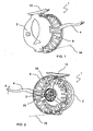
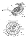
- the reel 1 according to the invention is formed mainly by a housing 2, a driving lever 4, a gearing 7, a wind up spool 8 of line 34 and finally a brake 9.
- Housing 2 has a reel support 10 that is provided to attach reel 1 to a common fishing rod anchoring point, not shown in the drawings.
- housing 2 has a main axis 3 and a secondary axis 5.
- Driving lever 4 is mounted on secondary axis 5, which can swivel against the force of elastic recovery means 11 of the rest position.
- secondary axis 5 is parallel to main axis 3, however, in an alternative embodiment, secondary axis 5 could be omitted and a driving lever 4 provided that swivels on main axis 3.
- driving lever 4 has a gearing sector 12 that meshes with a first pinion 6 mounted coaxially to main axis 3.
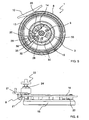
- First pinion 6 also meshes with an appendix 28 of a first pawl 32 of a one-way clutch 13, which is hinged on gearing 7 on an axis of the first pawl and which works against the force of a recovery spring 14.
- Gearing 7 is made up of a planetary train. Said planetary train is coaxial to main axis 3 of reel 1. This train comprises a ring gear 15, which meshes with three planet gears 16 carried on a planet gear carrier 17 attached to main axis 3 without the possibility of rotating, and in turn, planet gears 16 mesh with a second pinion 18 mounted freely on main axis 3. Ring gear 15 is mounted freely on planet gear-carrier 17. This one-way clutch 13 allows the movement to be transferred from first pinion 6 to ring gear 15 in the line retrieval movement 34. Second pinion 18 is connected by a positive locking 27 to spool 8.
- Brake 9 is made up of a brake disc 19 guided in the radial direction by ring gear 15 and by the brake's free wheel mechanism 20, consisting of a second pawl 29 that engages in an outer gear teeth 30 provided on ring gear 15, whereby a positive locking can be formed with ring gear 15 in the feed-out direction of line 34 from spool 8.
- Said brake 9 also comprises two break blocks 21 intended to brake the action of brake disc 19.
- braking tension regulating means 22 are also provided, consisting of a take-up spring 23, which can be regulated by a take-up screw 24.
- reel 1 provides a quick pressing system consisting of a fixing clip 25 that meshes with an undercutting 26 provided on main axis 3.
- the brake's free wheel mechanism 20 starts to operate, in other words, pawl 29 meshes with gear teeth 30 provided on ring gear 15, making brake disc 19 rotate with ring gear 15.
- brake blocks 21, which always compress brake disc 19, when braking the action of disc 19 and consequently ring gear 15, offer resistance to the feed-out of line 34 to counteract the force of the fish.
- lever 4 When it is desired to retrieve line 34 to gather the catch or re-cast, lever 4 is activated in the direction of arrow A in Figures 2 or 3 . Lever 4 swivels around secondary axis 5 and with its geared sector 12 meshed with first pinion 6, it causes first pinion 6 to rotate in the anti-clockwise direction in Figure 4 . Consequently, appendix 28 interlocks in the gearing in first pinion 6 and first pawl 32 drags ring gear 15 in the same rotation direction as first pinion 6.
- ring gear 15 would rotate in the clockwise direction, corresponding to the anti-clockwise direction in Figure 4 .
- said ring gear drags planet gears 16, which make second pinion 18 rotate, and consequently spool 8, in the anti-clockwise direction.
- spool 8 winds the line bringing the fish closer.
- the brake's free wheel mechanism 20 in other words corresponding second pawl 29, slips over gear teeth 30 on ring gear 15.
- brake disc 19 remains immobile while ring gear 15 rotates in the clockwise direction in Figure 2 .
- brake 9 is independent from the kinematic driving chain and that it only works when it is really necessary, in other words, in the feed-out of line 34 from spool 8. That is, brake 9 does not behave like a clutch. This prevents the brake acting as a torque limiter when the captured fish is particularly large. Consequently, it is guaranteed that driving lever 4 works effectively at all times, in other words, all the force applied by the user to lever 4 is actually transmitted to spool 8.
- spool 8 with a larger diameter, and in particular larger than 70 mm.
- the large wind up diameter of spool 8 reduces the shape memory effect, and therefore the performance of the rod is improved, as greater casting distances can be reached.
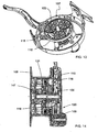
- Figures 9 to 16 show a second embodiment of the reel.
- Figures 14 , 15 and 16 show sections along the lines A-A, B-B and C-C of Figure 10 respectively.
- brake 109 of reel 101 comprises a first ring 135 and a second ring 136.
- First ring 135 has a first conical outer surface 137 that cooperates with second conical inner surface 138 of second ring 136 to produce the corresponding braking torque.
- second ring 136 has a fifth pinion 143 that meshes with a fourth pinion 141 that is part of free wheel mechanism 120.
- Free wheel mechanism 120 also comprises a one-way bearing 142 with a third pinion 140 which, in turn, meshes with a first outer gear teeth 139 provided on ring gear 115 of gearing 107.
- the force of the brake is regulated by regulating means 122.
- Cap 144 has a positive locking with first ring 135 in the form of a hexagonal screw.
- First ring 135 has an outer thread 145 which, as can be seen in detail in the section in Figure 16 , is guided in the inner thread 148 of a bushing 146, fixed to housing 102 by screws 149. So, when cap 144 is activated in the tightening direction of brake 109, first conical surface 137 of first ring 135 presses against second conical surface 138, which increases the friction between both surfaces and therefore increases the braking torque.
- ring gear 115 and second ring 136 are kinematically linked by first outer gear teeth 139 on ring gear 115, free wheel mechanism 120 and fifth gear 143.
- free wheel mechanism 120 is active. So, when ring gear 115 rotates, with its first outer gear teeth 139 it drags third pinion 140, which communicates the movement to fourth pinion 141 through one-way bearing 142. Fourth pinion 141 drags fifth pinion 143 of second ring 136. Finally, second ring 136 is braked by the relative friction between first and second conical surfaces 137, 138, which brakes the feed-out of line 134.
- free wheel mechanism 120 When the user retrieves the line using lever 104, free wheel mechanism 120 is deactivated, in other words, one-way bearing 142 does not transfer the movement of third pinion 140 to fourth pinion 141, whereby brake 109 remains inactive.
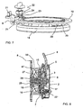
- Brake 8 comprises a brake disc 10 in the shape of a ring mounted whereby it floats, externally and concentrically on an outer blocking diameter 35 of ring gear 24.
- Brake disc 10 is caused to brake by two brake blocks 11a, 11b.
- the first break block 11a is integral with housing 2 and acts upon a first surface 36a of disc 10
- the second break block 11 b can be moved in the direction perpendicular to the second surface 36b of brake disc 10 by means 18 for regulating the force of brake 8.
- said regulating means 18 are made up of a take-up screw 20 that compresses a take-up spring 19. When compressed, take-up spring 19 pushes against second movable brake break block 11 b.
- Brake 209 comprises a brake disc 219 in the form of a ring mounted floating, externally and concentrically on an outer blocking diameter 250 of ring gear 215. Brake disc 219 is caused to brake by two brake blocks 221 a, 221 b.
- the second break block 221 b can be moved in the direction perpendicular to the second surface 251 b of brake disc 219 by means 222 for regulating the force of brake 219.
- said regulating means 222 are made up of a take-up screw 224 that compresses a take-up spring 223. When compressed, take-up spring 223 pushes against second movable break block 221 b.
- brake disc 219 has some notches 254 in its inner diameter 253 and the part of said notches located furthest from inner diameter 253 has the shape of a slope 255. Also between each notch 254 of brake disc 219 and outer blocking diameter 250 of ring gear 215 a rolling body 256 is provided. This unit forms free wheel mechanism 220 in this embodiment. When ring gear 215 rotates in the clockwise direction in Figure 20 , it drags said rolling bodies 256 in the same direction. So, rolling bodies 256 are blocked between ring gear 215 and brake disc 219, whereby brake disc 219 is dragged by ring gear 215, also in the clockwise direction. As already mentioned, brake blocks 221 that are always compressed by take-up spring 223 pressing on brake disc 219, produce a braking torque that can be regulated continuously from 0 Nm to completely blocking brake disc 219 and therefore the rotation of spool 208.
- the complete blocking of brake 9, 109, 209 makes it easier to remove the catch from the hook, because when the catch is on the shore, line feed-out can be completely avoided. For example, if the fish slips from the angler's hand just before removing the hook, the fish cannot move away from the shore.
- reel 1, 101, 201 improves various aspects of the known, state of the art reels. So, the line retrieval speed is considerable improved, which allows the angler to react much more efficiently to the force of the fish. Moreover, thanks to the greater length of line retrieved each time the driving lever is activated, it is possible to reduce the rod 's lurching movement with respect to the number of times that the rod lurches and the magnitude of the lurching action. The invention also proposes a much more efficient brake since it is only active at the times it is really needed.
- the invention can be used with all kinds of line calibres, with the subsequent advantages that this implies, in other words that the semi-automatic reel can be applied to all kinds fly fishing techniques, which does not happen with the semi-automatic and automatic reels of the state of the art.
Landscapes
- Life Sciences & Earth Sciences (AREA)
- Environmental Sciences (AREA)
- Animal Husbandry (AREA)
- Biodiversity & Conservation Biology (AREA)
- Braking Arrangements (AREA)
- Rolls And Other Rotary Bodies (AREA)
Claims (12)
- Rolle für das Fliegenfischen mit[a] einem Gehäuse (2, 102, 202),[b] einer Hauptachse 13, 103, 203),[c] einem Antriebsschwenkhbel 4, 104, 204),[d] einem elastischen Wiederherstellungsmittel (11, 111, 211) für die Hebelruhelage,[e] einem durch den Antriebshebel (4, 104, 204) angetriebenen ersten Zahnrad (6, 106, 206), das koaxial zur Hauptachse (3, 103, 203) ist,[f] einer Spule 8, 108, 208) zum Aufwickeln von Leine (34, 34, 234), die koaxial zur Hauptachse (3, 103, 203) vorgesehen ist,[g] einer Bremse (9, 109, 209) der Spule (8, 108, 206), und[h] einem Getriebe (7, 107, 207), das zwischen dem ersten Zahnrad (6, 106, 206) und der Spule (8, 108, 208) vorgesehen ist,gekennzeichnet dadurch, dass[i] das Getriebe (7, 107, 207) mindestens ein Planetengetriebe enthält,[j] das Planetengetriebe ein zweites Zahnrad (18, 118, 218), mindestens drei Planetenräder (16, 116, 216) und ein Hohlrad (15, 115, 215) enthält, und[k] das Hohlrad (15, 125, 215) über eine erste Einwegkupplung (13, 113, 213) mit dem ersten Zahnrad (6, 106, 206) verbunden ist.
- Rolle für das Fliegenfischen nach Anspruch 1, dadurch gekennzeichnet, dass sie eine zu der Hauptachse (3, 103, 203) parallele Sekundärachse (5, 105, 205) aufweist, wobei der Antriebshebel (4, 104, 204) um die Sekundärachse (5, 105, 205) herum schwenkt, und dass der Antriebshebel (4, 104, 204) an einem Ende einen mit dem ersten Zahnrad (6, 106, 206) kämmenden Getriebeabschnitt (12, 122, 212) enthält.
- Rolle für das Fliegenfischen nach Anspruch 1 oder 2, dadurch gekennzeichnet, dass sie eine zweite Einwegkupplung enthält, wobei der Antriebshebel (4, 104, 204) einen Sattel (31, 131, 231) aufweist, der das Ende des Hebels (4, 104, 204) mit dem Anfang des Getriebeabschnitts (12, 112, 212) verbindet, und dass der Sattel (31, 131, 231) keine Zähne aufweist, damit in einer Auslassrichtung der Leine (34, 134, 234) das erste Zahnrad (6, 106, 206) den Antriebshebel (4, 104, 204) nicht aktiviert.
- Rolle für das Fliegenfischen nach einem der vorhergehenden Ansprüche, dadurch gekennzeichnet, dass das Planetengetriebe vier von diesen Planetenrädern (16, 116, 216) enthält.
- Rolle für das Fliegenfischen nach einem der vorhergehenden Ansprüche, dadurch gekennzeichnet, dass[a] die Spule (8, 108, 208) in einer mechanisch starren Weise mit dem Getriebe (7, 107, 207) verbunden ist, wobei das Getriebe (7, 107, 207) und die Spule (8, 108, 208) eine starre kinematische Einheit (49, 149, 249) bilden,[b] die Kraft der Bremse (9, 109, 209) kontinuierlich reguliert werden kann,[c] die Bremse (9, 109, 209) einen Freilaufmechanismus (20, 120, 220) enthält und auf die starre kinematische Einheit (47, 147, 247) wirkt, undso dass in der Auslassrichtung der Leine (34, 134, 234) der Freilaufmechanismus (20, 120, 220) aktiv ist, während in der Aufwickelrichtung der Leine (34, 134, 234) der Freilaufmechanismus (20, 120, 220) inaktiv ist.
- Rolle für das Fliegenfischen nach Anspruch 5, dadurch gekennzeichnet, dass die Bremse (9, 209) auf eine Bremsscheibe (19, 219) wirKende Bremsblöcke (21, 221) enthält und dass sie sich außerhalb des Getribekraftlusses von dem Hebel zu der Spule (8, 208) befindet.
- Rolle für das Fliegenfischen nach Anspruch 6, dadurch gekennzeichnet, dass die Bremsscheibe (19, 219) koaxial zu dem Hohlrad (15, 215) ist und die Bremsblöcke (21, 221) mit dem Gehäuse (2, 202) einstückig ausgebildet sind.
- Rolle für das Fliegenfischen nach Anspruch 6 oder 7, dadurch gekennzeichnet, dass der Freilaufmechanismus (20) eine Außenverzahnung (30) an dem Hohlrad (15) und eine zweite Klinke (29) an der Bremsscheibe (19) enthält, wobei der Frei-Laufmechanismus (20) nur in der Auslassrichtung der Leine (34) arbeitet.
- Rolle für dass Fliegenfischen nach einem der Ansprüche 1 bis 8, dadurch gekennzeichnet, dass die Bremse (9, 209) Reguliermittel (22, 222) für die Bremsspannung enthält, wobei die Reguliermittel (22, 222) aus einer Aufnahmefeder (23, 223) und einer Aufnahmeschraube (24, 224) bestehen.
- Rolle für das Fliegenfischen nach Anspruch 5, dadurch gekennzeichnet, dass die Bremse (109) enthält[a] einen ersten Ring (135) mit einer ersten konischen Fläche (137), und[b] einen zweiten Drehring (136) mit einer zweiten konischen Flache (138), wobei die erste und zweite konische Fläche geeignet sind gegenseitig zusammenzuwirken, um ein Bremsmoment zu erzeugen, und dass[c] der zweite Ring (136) und das Getriebe (107) über den Freilaufmechanismus (120) gegenseitig zusammenwirken.
- Rolle für das Fliegenfischen nach Anspruch 10, dadurch gekennzeichnet, dass[a] der Freilaufmechanismus (120) ein Einweggetriebe (144) enthält, das ein drittes Zahnrad (142) und ein viertes Zahnrad (143) enthält,[b] der zweite Ring (138) ein fünftes zahnrad (145) enthält, und[c] das Hohlrad (115) des Getriebes (107) eine erste Außenverzahnung (139) enthält,so dass das fünfte Zahnrad (144) mit dem vierten Zahnrad (143) kämmt, während das dritte Zahnrad (142) mit dem Hohlrad (124) kämmt.
- Rolle für das Fliegenfischen nach einem der Ansprüche 1 bis 11, dadurch gekennzeichnet, dass die Spule (8, 108, 208) einen Wiederaufnahmeinnendurchmesser (33, 133, 233) für Leine (34, 134, 234) aufweist und dass der Innendurchmesser (33, 133, 233) größer als 70 mm ist.
Applications Claiming Priority (2)
| Application Number | Priority Date | Filing Date | Title |
|---|---|---|---|
| ES200602168A ES2276635B1 (es) | 2006-08-09 | 2006-08-09 | Carrete de pesca a la mosca. |
| ES200700001A ES2284405B1 (es) | 2007-01-02 | 2007-01-02 | "carrete de pesca a la mosca". |
Publications (2)
| Publication Number | Publication Date |
|---|---|
| EP1886558A1 EP1886558A1 (de) | 2008-02-13 |
| EP1886558B1 true EP1886558B1 (de) | 2011-06-29 |
Family
ID=38787610
Family Applications (2)
| Application Number | Title | Priority Date | Filing Date |
|---|---|---|---|
| EP07380225A Active EP1886558B1 (de) | 2006-08-09 | 2007-08-02 | Rolle für das Fliegenfischen |
| EP07380224A Active EP1897440B1 (de) | 2006-08-09 | 2007-08-02 | Rolle für das Fliegenfischen |
Family Applications After (1)
| Application Number | Title | Priority Date | Filing Date |
|---|---|---|---|
| EP07380224A Active EP1897440B1 (de) | 2006-08-09 | 2007-08-02 | Rolle für das Fliegenfischen |
Country Status (7)
| Country | Link |
|---|---|
| US (2) | US7464890B2 (de) |
| EP (2) | EP1886558B1 (de) |
| AT (2) | ATE514335T1 (de) |
| DE (1) | DE602007002022D1 (de) |
| DK (1) | DK1897440T3 (de) |
| ES (1) | ES2330896T3 (de) |
| PL (1) | PL1897440T3 (de) |
Families Citing this family (10)
| Publication number | Priority date | Publication date | Assignee | Title |
|---|---|---|---|---|
| US7798439B2 (en) * | 2008-04-08 | 2010-09-21 | Daiwa Seiko, Inc. | Fishing reel |
| KR101084560B1 (ko) * | 2008-11-10 | 2011-11-17 | 주식회사 코스피시테크 | 낚시용 베이트 릴 |
| US8757531B2 (en) * | 2011-08-10 | 2014-06-24 | Josh Bradley | Fly reel |
| DE102012104554B3 (de) * | 2012-05-25 | 2013-11-07 | Hubert Mayr | Angelrollen und Spule für eine Angelrolle |
| US9383160B1 (en) * | 2013-01-15 | 2016-07-05 | Bear Archery, Inc. | Bowfishing reel |
| US10010061B2 (en) * | 2015-03-18 | 2018-07-03 | Shimano Inc. | Spinning reel |
| US10091978B2 (en) | 2015-04-02 | 2018-10-09 | Mark E. Champion | Lever-operated fishing reel |
| CN104934809B (zh) * | 2015-04-23 | 2017-06-23 | 宁波德昌电机制造有限公司 | 一种具有连续自动收线能力的卷线装置 |
| US11785928B2 (en) * | 2019-10-17 | 2023-10-17 | TrikaUSA Inc. | Baitcaster with compound gear set |
| US12408646B2 (en) | 2022-10-25 | 2025-09-09 | Oclarkii, Llc | Systems and methods for semi-automatic fly-fishing reels |
Family Cites Families (16)
| Publication number | Priority date | Publication date | Assignee | Title |
|---|---|---|---|---|
| US2517776A (en) * | 1945-09-17 | 1950-08-08 | Louis B Feierabend | Automatic two-speed fishing reel |
| US2591338A (en) * | 1947-03-29 | 1952-04-01 | P & K Inc | Fishing reel |
| US3446453A (en) * | 1967-02-08 | 1969-05-27 | Shoe Form Co Inc | Fishing reel with combined line take-up and drag |
| US3806060A (en) | 1971-09-15 | 1974-04-23 | C Valentine | Fishing reel with planetary drive |
| US4148228A (en) * | 1976-08-18 | 1979-04-10 | Freeman James W | Variable speed fishing reel |
| GB2060332B (en) | 1979-10-23 | 1983-03-02 | Intrepid Sealey Ltd | Rotatable spool fishing reel |
| SE455257B (sv) | 1987-02-05 | 1988-07-04 | Bringsen Berne | Bromsmekanism for reglerbar bromsning av en pa en axel roterbar rulle |
| US4796831A (en) | 1987-10-16 | 1989-01-10 | Martin Automatic Fishing Reel Co., Inc. | Multiplier fly casting reel with anti-reversing mechanism |
| US5443218A (en) * | 1992-04-30 | 1995-08-22 | Ciocca; Quintino M. | Linear winding assembly |
| US6053445A (en) * | 1996-09-09 | 2000-04-25 | C-1 Design Group | Fly fishing reel with isolated conical drag |
| US5857632A (en) * | 1996-09-11 | 1999-01-12 | Flylogic, Inc. | Casting fishing reel with torque converter and clutch |
| EP1027826A1 (de) | 1999-02-09 | 2000-08-16 | Etter, Hugo | Fischerrolle, insbesondere Fliegenrolle |
| US20030168541A1 (en) * | 2002-03-08 | 2003-09-11 | Doug Hill | Fishing reel |
| US7374118B2 (en) * | 2002-10-18 | 2008-05-20 | Daiwa Seiko, Inc. | Fishing reel |
| FR2855371B1 (fr) * | 2003-05-28 | 2007-05-04 | Patrick Chaumier | Moulinet de peche a la mouche comportant des moyens d'accouplement selectif separes des moyens d'entrainement |
| DE202004011887U1 (de) * | 2004-07-28 | 2004-09-23 | Gerlach, Jens-Uwe | Angelrolle für das Flugangeln ohne feststehender Achse |
-
2007
- 2007-08-02 AT AT07380225T patent/ATE514335T1/de not_active IP Right Cessation
- 2007-08-02 DE DE602007002022T patent/DE602007002022D1/de active Active
- 2007-08-02 EP EP07380225A patent/EP1886558B1/de active Active
- 2007-08-02 DK DK07380224T patent/DK1897440T3/da active
- 2007-08-02 AT AT07380224T patent/ATE439765T1/de not_active IP Right Cessation
- 2007-08-02 ES ES07380224T patent/ES2330896T3/es active Active
- 2007-08-02 EP EP07380224A patent/EP1897440B1/de active Active
- 2007-08-02 PL PL07380224T patent/PL1897440T3/pl unknown
- 2007-08-07 US US11/834,862 patent/US7464890B2/en not_active Expired - Fee Related
- 2007-08-07 US US11/834,885 patent/US7464891B2/en not_active Expired - Fee Related
Also Published As
| Publication number | Publication date |
|---|---|
| ATE514335T1 (de) | 2011-07-15 |
| ES2330896T3 (es) | 2009-12-16 |
| US7464890B2 (en) | 2008-12-16 |
| PL1897440T3 (pl) | 2010-01-29 |
| EP1886558A1 (de) | 2008-02-13 |
| DK1897440T3 (da) | 2009-12-07 |
| EP1897440A1 (de) | 2008-03-12 |
| US20080035774A1 (en) | 2008-02-14 |
| US7464891B2 (en) | 2008-12-16 |
| ATE439765T1 (de) | 2009-09-15 |
| DE602007002022D1 (de) | 2009-10-01 |
| EP1897440B1 (de) | 2009-08-19 |
| US20080035773A1 (en) | 2008-02-14 |
Similar Documents
| Publication | Publication Date | Title |
|---|---|---|
| EP1886558B1 (de) | Rolle für das Fliegenfischen | |
| AU759992B2 (en) | Double bearing reel | |
| CN105265401B (zh) | 双轴承绕线轮和双轴承绕线轮的离合器机构 | |
| US2783952A (en) | Spinning reel | |
| US6915974B2 (en) | Level wind mechanism for a dual bearing reel | |
| US2843333A (en) | Spinning ratchet reel | |
| US2775057A (en) | Device for jettisoning snagged fishhooks | |
| US8876031B2 (en) | Fishing reel with dual spool spin axes | |
| US4509287A (en) | Fish trolling device | |
| US2964257A (en) | Heavy duty spinning reel | |
| US3085766A (en) | Spinning type fishing reel | |
| EP1011322B1 (de) | Vorrichtung zum fliegenfischen | |
| JP2525185Y2 (ja) | 釣り用リール | |
| US2621869A (en) | Combination spinning and casting fishing reel | |
| CN216674367U (zh) | 手动换档渔线轮 | |
| US2753130A (en) | Line fishing implement | |
| GB2433405A (en) | A fixed spool fishing reel | |
| JP6842756B2 (ja) | 魚釣り用リール | |
| US5029410A (en) | Fishing lure | |
| KR100372521B1 (ko) | 플라이 낚시 릴 | |
| CN116267829B (zh) | 手动换挡渔线轮 | |
| ES2366816T3 (es) | Carrete de pesca a la mosca. | |
| CN110583592B (zh) | 一种海钓盘 | |
| CN219612847U (zh) | 一种中心刹车单向刹车片渔线轮 | |
| KR20260012570A (ko) | 슬랙라인 리와인딩 장치를 구비한 베이트릴 |
Legal Events
| Date | Code | Title | Description |
|---|---|---|---|
| PUAI | Public reference made under article 153(3) epc to a published international application that has entered the european phase |
Free format text: ORIGINAL CODE: 0009012 |
|
| AK | Designated contracting states |
Kind code of ref document: A1 Designated state(s): AT BE BG CH CY CZ DE DK EE ES FI FR GB GR HU IE IS IT LI LT LU LV MC MT NL PL PT RO SE SI SK TR |
|
| AX | Request for extension of the european patent |
Extension state: AL BA HR MK YU |
|
| 17P | Request for examination filed |
Effective date: 20080701 |
|
| AKX | Designation fees paid |
Designated state(s): AT BE BG CH CY CZ DE DK EE ES FI FR GB GR HU IE IS IT LI LT LU LV MC MT NL PL PT RO SE SI SK TR |
|
| AXX | Extension fees paid |
Extension state: HR Payment date: 20080701 |
|
| RIN1 | Information on inventor provided before grant (corrected) |
Inventor name: BAO COUTADO, CARLOS |
|
| GRAP | Despatch of communication of intention to grant a patent |
Free format text: ORIGINAL CODE: EPIDOSNIGR1 |
|
| RAP1 | Party data changed (applicant data changed or rights of an application transferred) |
Owner name: BAWER TECHNOLOGY S.L |
|
| GRAS | Grant fee paid |
Free format text: ORIGINAL CODE: EPIDOSNIGR3 |
|
| GRAA | (expected) grant |
Free format text: ORIGINAL CODE: 0009210 |
|
| AK | Designated contracting states |
Kind code of ref document: B1 Designated state(s): AT BE BG CH CY CZ DE DK EE ES FI FR GB GR HU IE IS IT LI LT LU LV MC MT NL PL PT RO SE SI SK TR |
|
| AX | Request for extension of the european patent |
Extension state: HR |
|
| REG | Reference to a national code |
Ref country code: GB Ref legal event code: FG4D |
|
| REG | Reference to a national code |
Ref country code: CH Ref legal event code: EP |
|
| REG | Reference to a national code |
Ref country code: CH Ref legal event code: NV Representative=s name: MICHELI & CIE SA |
|
| REG | Reference to a national code |
Ref country code: IE Ref legal event code: FG4D |
|
| REG | Reference to a national code |
Ref country code: DE Ref legal event code: R096 Ref document number: 602007015498 Country of ref document: DE Effective date: 20110825 |
|
| REG | Reference to a national code |
Ref country code: NL Ref legal event code: T3 |
|
| REG | Reference to a national code |
Ref country code: SE Ref legal event code: TRGR |
|
| REG | Reference to a national code |
Ref country code: ES Ref legal event code: FG2A Ref document number: 2366816 Country of ref document: ES Kind code of ref document: T3 Effective date: 20111025 |
|
| PG25 | Lapsed in a contracting state [announced via postgrant information from national office to epo] |
Ref country code: LT Free format text: LAPSE BECAUSE OF FAILURE TO SUBMIT A TRANSLATION OF THE DESCRIPTION OR TO PAY THE FEE WITHIN THE PRESCRIBED TIME-LIMIT Effective date: 20110629 |
|
| PGFP | Annual fee paid to national office [announced via postgrant information from national office to epo] |
Ref country code: CH Payment date: 20110721 Year of fee payment: 5 |
|
| PG25 | Lapsed in a contracting state [announced via postgrant information from national office to epo] |
Ref country code: GR Free format text: LAPSE BECAUSE OF FAILURE TO SUBMIT A TRANSLATION OF THE DESCRIPTION OR TO PAY THE FEE WITHIN THE PRESCRIBED TIME-LIMIT Effective date: 20110930 Ref country code: LV Free format text: LAPSE BECAUSE OF FAILURE TO SUBMIT A TRANSLATION OF THE DESCRIPTION OR TO PAY THE FEE WITHIN THE PRESCRIBED TIME-LIMIT Effective date: 20110629 Ref country code: AT Free format text: LAPSE BECAUSE OF FAILURE TO SUBMIT A TRANSLATION OF THE DESCRIPTION OR TO PAY THE FEE WITHIN THE PRESCRIBED TIME-LIMIT Effective date: 20110629 Ref country code: SI Free format text: LAPSE BECAUSE OF FAILURE TO SUBMIT A TRANSLATION OF THE DESCRIPTION OR TO PAY THE FEE WITHIN THE PRESCRIBED TIME-LIMIT Effective date: 20110629 Ref country code: FI Free format text: LAPSE BECAUSE OF FAILURE TO SUBMIT A TRANSLATION OF THE DESCRIPTION OR TO PAY THE FEE WITHIN THE PRESCRIBED TIME-LIMIT Effective date: 20110629 |
|
| PG25 | Lapsed in a contracting state [announced via postgrant information from national office to epo] |
Ref country code: BE Free format text: LAPSE BECAUSE OF FAILURE TO SUBMIT A TRANSLATION OF THE DESCRIPTION OR TO PAY THE FEE WITHIN THE PRESCRIBED TIME-LIMIT Effective date: 20110629 Ref country code: MT Free format text: LAPSE BECAUSE OF FAILURE TO SUBMIT A TRANSLATION OF THE DESCRIPTION OR TO PAY THE FEE WITHIN THE PRESCRIBED TIME-LIMIT Effective date: 20110629 |
|
| PG25 | Lapsed in a contracting state [announced via postgrant information from national office to epo] |
Ref country code: CZ Free format text: LAPSE BECAUSE OF FAILURE TO SUBMIT A TRANSLATION OF THE DESCRIPTION OR TO PAY THE FEE WITHIN THE PRESCRIBED TIME-LIMIT Effective date: 20110629 Ref country code: PT Free format text: LAPSE BECAUSE OF FAILURE TO SUBMIT A TRANSLATION OF THE DESCRIPTION OR TO PAY THE FEE WITHIN THE PRESCRIBED TIME-LIMIT Effective date: 20111031 Ref country code: EE Free format text: LAPSE BECAUSE OF FAILURE TO SUBMIT A TRANSLATION OF THE DESCRIPTION OR TO PAY THE FEE WITHIN THE PRESCRIBED TIME-LIMIT Effective date: 20110629 Ref country code: IS Free format text: LAPSE BECAUSE OF FAILURE TO SUBMIT A TRANSLATION OF THE DESCRIPTION OR TO PAY THE FEE WITHIN THE PRESCRIBED TIME-LIMIT Effective date: 20111029 |
|
| PG25 | Lapsed in a contracting state [announced via postgrant information from national office to epo] |
Ref country code: CY Free format text: LAPSE BECAUSE OF FAILURE TO SUBMIT A TRANSLATION OF THE DESCRIPTION OR TO PAY THE FEE WITHIN THE PRESCRIBED TIME-LIMIT Effective date: 20110629 Ref country code: PL Free format text: LAPSE BECAUSE OF FAILURE TO SUBMIT A TRANSLATION OF THE DESCRIPTION OR TO PAY THE FEE WITHIN THE PRESCRIBED TIME-LIMIT Effective date: 20110629 Ref country code: RO Free format text: LAPSE BECAUSE OF FAILURE TO SUBMIT A TRANSLATION OF THE DESCRIPTION OR TO PAY THE FEE WITHIN THE PRESCRIBED TIME-LIMIT Effective date: 20110629 Ref country code: SK Free format text: LAPSE BECAUSE OF FAILURE TO SUBMIT A TRANSLATION OF THE DESCRIPTION OR TO PAY THE FEE WITHIN THE PRESCRIBED TIME-LIMIT Effective date: 20110629 |
|
| PG25 | Lapsed in a contracting state [announced via postgrant information from national office to epo] |
Ref country code: MC Free format text: LAPSE BECAUSE OF NON-PAYMENT OF DUE FEES Effective date: 20110831 |
|
| PLBE | No opposition filed within time limit |
Free format text: ORIGINAL CODE: 0009261 |
|
| STAA | Information on the status of an ep patent application or granted ep patent |
Free format text: STATUS: NO OPPOSITION FILED WITHIN TIME LIMIT |
|
| 26N | No opposition filed |
Effective date: 20120330 |
|
| PG25 | Lapsed in a contracting state [announced via postgrant information from national office to epo] |
Ref country code: DK Free format text: LAPSE BECAUSE OF FAILURE TO SUBMIT A TRANSLATION OF THE DESCRIPTION OR TO PAY THE FEE WITHIN THE PRESCRIBED TIME-LIMIT Effective date: 20110629 |
|
| REG | Reference to a national code |
Ref country code: DE Ref legal event code: R097 Ref document number: 602007015498 Country of ref document: DE Effective date: 20120330 |
|
| PGFP | Annual fee paid to national office [announced via postgrant information from national office to epo] |
Ref country code: IE Payment date: 20120810 Year of fee payment: 6 Ref country code: SE Payment date: 20120813 Year of fee payment: 6 |
|
| PGFP | Annual fee paid to national office [announced via postgrant information from national office to epo] |
Ref country code: NL Payment date: 20120809 Year of fee payment: 6 |
|
| PG25 | Lapsed in a contracting state [announced via postgrant information from national office to epo] |
Ref country code: LU Free format text: LAPSE BECAUSE OF NON-PAYMENT OF DUE FEES Effective date: 20110802 |
|
| PG25 | Lapsed in a contracting state [announced via postgrant information from national office to epo] |
Ref country code: BG Free format text: LAPSE BECAUSE OF FAILURE TO SUBMIT A TRANSLATION OF THE DESCRIPTION OR TO PAY THE FEE WITHIN THE PRESCRIBED TIME-LIMIT Effective date: 20110929 |
|
| PG25 | Lapsed in a contracting state [announced via postgrant information from national office to epo] |
Ref country code: TR Free format text: LAPSE BECAUSE OF FAILURE TO SUBMIT A TRANSLATION OF THE DESCRIPTION OR TO PAY THE FEE WITHIN THE PRESCRIBED TIME-LIMIT Effective date: 20110629 |
|
| PG25 | Lapsed in a contracting state [announced via postgrant information from national office to epo] |
Ref country code: HU Free format text: LAPSE BECAUSE OF FAILURE TO SUBMIT A TRANSLATION OF THE DESCRIPTION OR TO PAY THE FEE WITHIN THE PRESCRIBED TIME-LIMIT Effective date: 20110629 |
|
| PGFP | Annual fee paid to national office [announced via postgrant information from national office to epo] |
Ref country code: DE Payment date: 20130731 Year of fee payment: 7 Ref country code: ES Payment date: 20130628 Year of fee payment: 7 |
|
| PGFP | Annual fee paid to national office [announced via postgrant information from national office to epo] |
Ref country code: GB Payment date: 20130731 Year of fee payment: 7 Ref country code: FR Payment date: 20130808 Year of fee payment: 7 |
|
| PGFP | Annual fee paid to national office [announced via postgrant information from national office to epo] |
Ref country code: IT Payment date: 20130806 Year of fee payment: 7 |
|
| REG | Reference to a national code |
Ref country code: NL Ref legal event code: V1 Effective date: 20140301 |
|
| REG | Reference to a national code |
Ref country code: CH Ref legal event code: PL |
|
| REG | Reference to a national code |
Ref country code: SE Ref legal event code: EUG |
|
| PG25 | Lapsed in a contracting state [announced via postgrant information from national office to epo] |
Ref country code: CH Free format text: LAPSE BECAUSE OF NON-PAYMENT OF DUE FEES Effective date: 20130831 Ref country code: SE Free format text: LAPSE BECAUSE OF NON-PAYMENT OF DUE FEES Effective date: 20130803 Ref country code: LI Free format text: LAPSE BECAUSE OF NON-PAYMENT OF DUE FEES Effective date: 20130831 Ref country code: NL Free format text: LAPSE BECAUSE OF NON-PAYMENT OF DUE FEES Effective date: 20140301 |
|
| REG | Reference to a national code |
Ref country code: IE Ref legal event code: MM4A |
|
| PG25 | Lapsed in a contracting state [announced via postgrant information from national office to epo] |
Ref country code: IE Free format text: LAPSE BECAUSE OF NON-PAYMENT OF DUE FEES Effective date: 20130802 |
|
| REG | Reference to a national code |
Ref country code: DE Ref legal event code: R119 Ref document number: 602007015498 Country of ref document: DE |
|
| GBPC | Gb: european patent ceased through non-payment of renewal fee |
Effective date: 20140802 |
|
| PG25 | Lapsed in a contracting state [announced via postgrant information from national office to epo] |
Ref country code: IT Free format text: LAPSE BECAUSE OF NON-PAYMENT OF DUE FEES Effective date: 20140802 |
|
| REG | Reference to a national code |
Ref country code: DE Ref legal event code: R119 Ref document number: 602007015498 Country of ref document: DE Effective date: 20150303 |
|
| REG | Reference to a national code |
Ref country code: FR Ref legal event code: ST Effective date: 20150430 |
|
| PG25 | Lapsed in a contracting state [announced via postgrant information from national office to epo] |
Ref country code: DE Free format text: LAPSE BECAUSE OF NON-PAYMENT OF DUE FEES Effective date: 20150303 Ref country code: GB Free format text: LAPSE BECAUSE OF NON-PAYMENT OF DUE FEES Effective date: 20140802 |
|
| PG25 | Lapsed in a contracting state [announced via postgrant information from national office to epo] |
Ref country code: FR Free format text: LAPSE BECAUSE OF NON-PAYMENT OF DUE FEES Effective date: 20140901 |
|
| PG25 | Lapsed in a contracting state [announced via postgrant information from national office to epo] |
Ref country code: ES Free format text: LAPSE BECAUSE OF NON-PAYMENT OF DUE FEES Effective date: 20140803 |