EP1886706A1 - Druckbegrenzungsventil, im Besonderen für medizinisches Gerät zur assistierten Beatmung - Google Patents
Druckbegrenzungsventil, im Besonderen für medizinisches Gerät zur assistierten Beatmung Download PDFInfo
- Publication number
- EP1886706A1 EP1886706A1 EP06118580A EP06118580A EP1886706A1 EP 1886706 A1 EP1886706 A1 EP 1886706A1 EP 06118580 A EP06118580 A EP 06118580A EP 06118580 A EP06118580 A EP 06118580A EP 1886706 A1 EP1886706 A1 EP 1886706A1
- Authority
- EP
- European Patent Office
- Prior art keywords
- flat spring
- valve according
- flow control
- hollow body
- control element
- Prior art date
- Legal status (The legal status is an assumption and is not a legal conclusion. Google has not performed a legal analysis and makes no representation as to the accuracy of the status listed.)
- Granted
Links
Images


Classifications
-
- A—HUMAN NECESSITIES
- A61—MEDICAL OR VETERINARY SCIENCE; HYGIENE
- A61M—DEVICES FOR INTRODUCING MEDIA INTO, OR ONTO, THE BODY; DEVICES FOR TRANSDUCING BODY MEDIA OR FOR TAKING MEDIA FROM THE BODY; DEVICES FOR PRODUCING OR ENDING SLEEP OR STUPOR
- A61M16/00—Devices for influencing the respiratory system of patients by gas treatment, e.g. ventilators; Tracheal tubes
- A61M16/20—Valves specially adapted to medical respiratory devices
- A61M16/208—Non-controlled one-way valves, e.g. exhalation, check, pop-off non-rebreathing valves
- A61M16/209—Relief valves
-
- A—HUMAN NECESSITIES
- A62—LIFE-SAVING; FIRE-FIGHTING
- A62B—DEVICES, APPARATUS OR METHODS FOR LIFE-SAVING
- A62B9/00—Component parts for respiratory or breathing apparatus
- A62B9/02—Valves
-
- F—MECHANICAL ENGINEERING; LIGHTING; HEATING; WEAPONS; BLASTING
- F16—ENGINEERING ELEMENTS AND UNITS; GENERAL MEASURES FOR PRODUCING AND MAINTAINING EFFECTIVE FUNCTIONING OF MACHINES OR INSTALLATIONS; THERMAL INSULATION IN GENERAL
- F16K—VALVES; TAPS; COCKS; ACTUATING-FLOATS; DEVICES FOR VENTING OR AERATING
- F16K17/00—Safety valves; Equalising valves, e.g. pressure relief valves
- F16K17/02—Safety valves; Equalising valves, e.g. pressure relief valves opening on surplus pressure on one side; closing on insufficient pressure on one side
- F16K17/04—Safety valves; Equalising valves, e.g. pressure relief valves opening on surplus pressure on one side; closing on insufficient pressure on one side spring-loaded
- F16K17/0493—Safety valves; Equalising valves, e.g. pressure relief valves opening on surplus pressure on one side; closing on insufficient pressure on one side spring-loaded with a spring other than a helicoidal spring
Definitions
- the present invention relates to a pressure limiting valve, particularly for medical assisted-ventilation equipment.
- One of the possible assisted-ventilation techniques is performed by using a bag made of elastic material, which is provided with an intake and a delivery; the intake is associated by means of a duct to a source for supplying air and oxygen under pressure, and the delivery is associated by means of a connector to a device for leading to the respiratory system of a patient, such as a mask or a tracheal tube.
- Air is introduced in the patient by a physician or by a health worker by applying pressure to the elastic bag, while the subsequent expiration step occurs due to elastic return of the lungs.
- the valve limits the inflow pressure according to the physical or clinical characteristics of the patient.
- valves limit the air inflow pressure but do not limit the volume of the air, which is instead determined by the supply source.
- a first type of valve comprises a body in which an intake port and a vent port are formed; a flat element is accommodated within the body and is kept in a position for closing the intake port by a helical spring made of metal, which is conveniently preloaded.
- the valve opens when the supplied air pressure is higher than a threshold value determined by the resistance of the spring.
- Means for adjusting the load of the spring are provided, and by acting on said means it is possible to modify the threshold value of the pressure above which the valve opens.
- valves are structurally complicated, since they are constituted by numerous components and have significant construction costs.
- a second type is constituted by a valve of the faucet type, which comprises a cylindrical jacket provided with an intake port and a discharge port and inside which a hollow cylindrical body is accommodated so that it can rotate and substantially snugly, said body being provided with a partition for blocking the venting port which has an inclined contour.
- a larger or smaller opening of the venting port corresponds to different angular positions of the cylindrical body and therefore of the corresponding partition.
- valve is simple and cheap to manufacture and allows, by means of the angular positioning of the flow control partition, to adjust the maximum insufflation pressure, it does not however allow high precision in adjustment and exposes the patient to the danger of severe lung damage if the venting port is accidentally left in the fully closed position, therefore requiring adequate preparation of physicians and/or health workers.
- the aim of the present invention is to eliminate the above mentioned drawbacks of known valves, by providing a pressure limiting valve particularly for medical assisted-ventilation equipment which allows safe use for the patient.
- Another object of the present invention is to allow accurate adjustment of the maximum pressure threshold value at which the valve opens, so as to adapt it to the characteristics of the patient.
- Another object of the present invention is to ensure use of the valve even in combination with the use of diagnostic equipment which uses a magnetic field, such as for example magnetic-resonance equipment.
- an object of the present invention is to provide a valve which has a simple structure, is relatively easy to provide in practice, safe in use, effective in operation and has a relatively low cost.
- the present pressure limiting valve particularly for medical assisted-ventilation equipment, which comprises a hollow body provided with an intake port and a delivery port for a fluid and a flow control element for controlling the intake port, characterized in that it comprises a flat spring which is accommodated within the hollow body, is arranged substantially at right angles to the input stream of the fluid and has at least one end which is rigidly associated with the hollow body and rigidly supports the flow control element, the flat spring being flexible in the direction in which the flow control element moves away from the intake port at a presettable threshold value of the pressure applied by the fluid entering from the intake port.
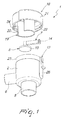
- the reference numeral 1 generally designates a pressure limiting valve.
- the valve 1 comprises a hollow body 2, which is provided with an intake port 3 and a discharge port 4 for a fluid.
- valve 1 can be connected by means of an intake connector 5, arranged at the intake port 3, to a source for the external supply of the fluid, which is constituted generally by a gaseous compound of air and oxygen.
- the discharge port 4 of the gaseous compound is instead formed by a vent 6.
- the hollow body 2 is substantially cylindrical with a circular transverse cross-section, at one end of which the intake opening 5 is formed, said body being open at the opposite end.
- the vent 6 is tubular and is arranged on the side wall of the hollow body 2 with an arrangement which is substantially perpendicular to the intake opening 5.
- the valve 1 further comprises a flat spring 7, which is accommodated within the hollow body 2 and has an end which is rigidly associated therewith and supports a flow control element 8 for the intake port 3.
- the flat spring 7 has a constant transverse cross-section and is arranged substantially at right angles to the fluid inflow stream.
- the flat spring 7 can further flex in the direction in which the flow control element 8 moves away from the intake port 3 at a presettable threshold value of the pressure applied by the fluid at the intake port 3.
- the flat spring 7 is supported in a cantilever fashion by the hollow body 2 and the flow control element 8 is rigidly associated proximate to the free end thereof.
- the flat spring 7 and the flow control element 8 are provided monolithically, for example by thermoforming a plastic material of the elastically deformable type, such as silicone or polyurethane.
- the flat spring 7 has a tab 9 for supporting the flow control element 8.
- the flow control element 8 is constituted by a flat element 10 which is substantially circular
- the tab 9 is constituted by a tubular element which is arranged substantially at right angles respectively to the longitudinal axis of the flat spring 7 and to the plane of arrangement of the flat element 10.
- the flat element 10 can be engaged hermetically in a seat 11 which is formed at the intake port 3 and is substantially annular and flared so as to converge toward the intake port 3.
- Means for coupling to the hollow body 2 the end of the flat spring 7 that lies opposite the flow control element 8 are provided.
- Said coupling means comprise a guide 12, which has substantially a prism-like dovetail shape and runs substantially longitudinally with respect to the hollow body 2.
- the guide 12 comprises a groove 13, with which an anchoring end 14 of the flat spring 7 mates which lies opposite the end that supports the flat element 10 and can be inserted in the groove 13 through an opening 15 provided proximate to the edge 16 of the hollow body 2 on its open end.
- the side walls 17 guide the flexing of the spring along a direction for moving the flat element 10 away or toward the intake port 3, avoiding lateral inflections thereof.
- the valve 1 further comprises means 18 for adjusting the pressure threshold value.
- the adjustment means 18 comprise elements for adjusting the flexibility of the flat spring 7.
- the adjustment elements comprise an abutment element 19, which is adapted to make contact in at least one point or transverse line with the face of the flat spring 7 that lies opposite the face that supports the flat element 10 and is associated with the hollow body 2, which can move by sliding along the length of the flat spring 7.
- the movement of the abutment element 19 along the longitudinal axis of the flat spring 7 allows a variation of the length of the useful portion thereof formed between the end for supporting the flap 10 and the point or transverse line of contact, consequently varying the flexibility of the spring.
- a movement of the abutment element 19 toward the flat element 10 leads to a reduction of the longitudinal size of said useful portion, consequently reducing the flexibility of the flat spring 7 and increasing the corresponding pressure threshold value; a movement of the abutment element 19 away from the flat element 10 leads to an increase in the longitudinal measurement of the useful portion, with a consequent increase in the flexibility of the flat spring 7 and a consequent decrease of the pressure threshold value.
- the abutment element 19 is constituted by a spiral wall 20, which is rotatably associated with the hollow body 2.
- the spiral wall 20 is fixed, at its end which lies opposite the one suitable to make contact with the flat spring 7, to the internal face of an annular element 21, which is rotatably connected to the hollow body 2 at the open end thereof.
- the annular element 21 has an annular collar 22, which protrudes toward the center on its internal surface.
- a ring 23 for fixing the annular element 21 is formed so as to protrude toward the center on the outer surface of the hollow body 2 and proximate to the edge 16.
- the annular collar 22 engages below the fixing ring 23, avoiding the extraction of the annular element 21.
- Means are provided for stopping the rotation of the annular element 21 in two configurations for adjusting the valve 1 at maximum and minimum pressure threshold value limit.
- the annular element 21 has a cylindrical shape with a substantially circular cross-section, and said stop means comprise at least one portion of its side wall which protrudes inward and a first tooth 24 and a second tooth 25 formed at its ends.
- the rotation of the annular element 21 with respect to the hollow body 2 is limited by the contact of the first tooth 24 and the second tooth 25 with a protrusion 26 on the outer surface of the hollow body 2 at the guide 12.
- the rotation of the spiral wall 20 rigidly coupled to the annular element 21 and its particular spiral shape allow the movement of a line of contact between the spiral wall 20 and the flat spring 7 from a point of maximum pressure threshold, designated by the reference numeral 27 in Figure 4, in which the first tooth 24 makes contact with the protrusion 26, to a minimum pressure threshold point, designated by the reference numeral 28 in Figure 5, in which the second tooth 25 makes contact with the protrusion 26.
- the valve 1 is provided with means for locking the end of the flat spring 7 which is rigidly associated with the hollow body 2.
- the locking means are formed by the action of the spiral wall 20 in contrast with the sliding of the anchoring end 14 within the groove 13, preventing its exit from the opening 15.
- the flat spring 7 has a variable transverse cross-section, which preferably increases from the end that is rigidly associated with the hollow body 2 to the end for supporting the flat element 10 so as to allow amplified adjustments of the pressure threshold value for minimal movements of the line of contact of the spiral wall 20 along the longitudinal axis of the flat spring 7.
- the valve 1 is applied to assisted-ventilation equipment.
- it is connected by means of the intake opening 5 to a connector which is interposed between the delivery of an elastic bag and a mask or tracheal tube which can be applied to a patient.
- the elastic bag is further provided with an intake which is connected to an external source for supplying a gaseous compound under pressure.
- the value of the pressure threshold of the gaseous compound to be insufflated is adjusted by turning the annular element 21 with respect to the body 2 of the valve. This adjustment is performed according to the build, age and clinical condition of the patient.
- the gaseous compound is insufflated by means of a series of successive pressing actions applied to the bag by a doctor or health worker.
- the flat element 10 is engaged in the seat 11 and closes hermetically the intake port 3.
- the portion of the flat spring 7 that is formed between the transverse line of contact with the spiral wall 20 and the end for supporting the flat element 10 flexes, moving the flat element 10 away from the seat 11 and opening the intake port 3.
- the gaseous compound then enters from the intake opening 5, the stream passes through the intake port 3, continues within the hollow body 2, and exits from the vent 6 through the discharge port 4.
- the presence of the adjustment means described above allows accurate adjustment of the maximum pressure threshold value at which the valve opens, so as to adapt it precisely to the characteristics of the patient.
Landscapes
- Health & Medical Sciences (AREA)
- Pulmonology (AREA)
- Engineering & Computer Science (AREA)
- General Health & Medical Sciences (AREA)
- Life Sciences & Earth Sciences (AREA)
- Public Health (AREA)
- Heart & Thoracic Surgery (AREA)
- Hematology (AREA)
- Anesthesiology (AREA)
- Animal Behavior & Ethology (AREA)
- Emergency Medicine (AREA)
- Biomedical Technology (AREA)
- Veterinary Medicine (AREA)
- General Engineering & Computer Science (AREA)
- Emergency Management (AREA)
- Business, Economics & Management (AREA)
- Mechanical Engineering (AREA)
- Safety Valves (AREA)
- Prostheses (AREA)
Priority Applications (3)
| Application Number | Priority Date | Filing Date | Title |
|---|---|---|---|
| DE602006019717T DE602006019717D1 (de) | 2006-08-08 | 2006-08-08 | Druckbegrenzungsventil, im Besonderen für medizinisches Gerät zur assistierten Beatmung |
| AT06118580T ATE495780T1 (de) | 2006-08-08 | 2006-08-08 | Druckbegrenzungsventil, im besonderen für medizinisches gerät zur assistierten beatmung |
| EP06118580A EP1886706B1 (de) | 2006-08-08 | 2006-08-08 | Druckbegrenzungsventil, im Besonderen für medizinisches Gerät zur assistierten Beatmung |
Applications Claiming Priority (1)
| Application Number | Priority Date | Filing Date | Title |
|---|---|---|---|
| EP06118580A EP1886706B1 (de) | 2006-08-08 | 2006-08-08 | Druckbegrenzungsventil, im Besonderen für medizinisches Gerät zur assistierten Beatmung |
Publications (2)
| Publication Number | Publication Date |
|---|---|
| EP1886706A1 true EP1886706A1 (de) | 2008-02-13 |
| EP1886706B1 EP1886706B1 (de) | 2011-01-19 |
Family
ID=37575158
Family Applications (1)
| Application Number | Title | Priority Date | Filing Date |
|---|---|---|---|
| EP06118580A Active EP1886706B1 (de) | 2006-08-08 | 2006-08-08 | Druckbegrenzungsventil, im Besonderen für medizinisches Gerät zur assistierten Beatmung |
Country Status (3)
| Country | Link |
|---|---|
| EP (1) | EP1886706B1 (de) |
| AT (1) | ATE495780T1 (de) |
| DE (1) | DE602006019717D1 (de) |
Cited By (1)
| Publication number | Priority date | Publication date | Assignee | Title |
|---|---|---|---|---|
| US11898646B2 (en) | 2019-06-25 | 2024-02-13 | Intersurgical Ag | Adjustable valve |
Citations (2)
| Publication number | Priority date | Publication date | Assignee | Title |
|---|---|---|---|---|
| GB1593871A (en) * | 1977-03-10 | 1981-07-22 | Expo Safety Systems Ltd | Pressure relief valves |
| EP0923959A1 (de) * | 1997-12-15 | 1999-06-23 | Siemens-Elema AB | Ventil zum Regeln eines Gasflusses |
-
2006
- 2006-08-08 DE DE602006019717T patent/DE602006019717D1/de active Active
- 2006-08-08 EP EP06118580A patent/EP1886706B1/de active Active
- 2006-08-08 AT AT06118580T patent/ATE495780T1/de not_active IP Right Cessation
Patent Citations (2)
| Publication number | Priority date | Publication date | Assignee | Title |
|---|---|---|---|---|
| GB1593871A (en) * | 1977-03-10 | 1981-07-22 | Expo Safety Systems Ltd | Pressure relief valves |
| EP0923959A1 (de) * | 1997-12-15 | 1999-06-23 | Siemens-Elema AB | Ventil zum Regeln eines Gasflusses |
Cited By (1)
| Publication number | Priority date | Publication date | Assignee | Title |
|---|---|---|---|---|
| US11898646B2 (en) | 2019-06-25 | 2024-02-13 | Intersurgical Ag | Adjustable valve |
Also Published As
| Publication number | Publication date |
|---|---|
| ATE495780T1 (de) | 2011-02-15 |
| EP1886706B1 (de) | 2011-01-19 |
| DE602006019717D1 (de) | 2011-03-03 |
Similar Documents
| Publication | Publication Date | Title |
|---|---|---|
| US12102771B2 (en) | Pressure regulating valve | |
| AU2022204843B2 (en) | Breathing assistance apparatus | |
| US11759616B2 (en) | Connector with valve for negative pressure wound therapy system | |
| US8567399B2 (en) | Methods and devices for providing inspiratory and expiratory flow relief during ventilation therapy | |
| US8573208B2 (en) | Exhaust assembly | |
| US11931541B2 (en) | Connector for selective occlusion of drainage tube | |
| BRPI0717547A2 (pt) | Válvula de redução de pressão, método para prover um gás de respiração, e, aparelho para fornecer um fluxo de gás de pressão positiva para uma via aérea de um paciente | |
| EP3638350B1 (de) | Nasale patientenschnittstellenanordnungund beatmungsvorrichtung | |
| EP1886706B1 (de) | Druckbegrenzungsventil, im Besonderen für medizinisches Gerät zur assistierten Beatmung | |
| US9295819B2 (en) | Fluid supply body and balloon catheter | |
| BR102014003346A2 (pt) | Dispositivo manual para assistência à tosse |
Legal Events
| Date | Code | Title | Description |
|---|---|---|---|
| PUAI | Public reference made under article 153(3) epc to a published international application that has entered the european phase |
Free format text: ORIGINAL CODE: 0009012 |
|
| AK | Designated contracting states |
Kind code of ref document: A1 Designated state(s): AT BE BG CH CY CZ DE DK EE ES FI FR GB GR HU IE IS IT LI LT LU LV MC NL PL PT RO SE SI SK TR |
|
| AX | Request for extension of the european patent |
Extension state: AL BA HR MK YU |
|
| 17P | Request for examination filed |
Effective date: 20080721 |
|
| AKX | Designation fees paid |
Designated state(s): AT BE BG CH CY CZ DE DK EE ES FI FR GB GR HU IE IS IT LI LT LU LV MC NL PL PT RO SE SI SK TR |
|
| RAP1 | Party data changed (applicant data changed or rights of an application transferred) |
Owner name: TELEFLEX MEDICAL EUROPE LTD |
|
| GRAP | Despatch of communication of intention to grant a patent |
Free format text: ORIGINAL CODE: EPIDOSNIGR1 |
|
| GRAS | Grant fee paid |
Free format text: ORIGINAL CODE: EPIDOSNIGR3 |
|
| GRAA | (expected) grant |
Free format text: ORIGINAL CODE: 0009210 |
|
| AK | Designated contracting states |
Kind code of ref document: B1 Designated state(s): AT BE BG CH CY CZ DE DK EE ES FI FR GB GR HU IE IS IT LI LT LU LV MC NL PL PT RO SE SI SK TR |
|
| REG | Reference to a national code |
Ref country code: GB Ref legal event code: FG4D |
|
| REG | Reference to a national code |
Ref country code: CH Ref legal event code: EP |
|
| REG | Reference to a national code |
Ref country code: IE Ref legal event code: FG4D |
|
| REF | Corresponds to: |
Ref document number: 602006019717 Country of ref document: DE Date of ref document: 20110303 Kind code of ref document: P |
|
| REG | Reference to a national code |
Ref country code: DE Ref legal event code: R096 Ref document number: 602006019717 Country of ref document: DE Effective date: 20110303 |
|
| REG | Reference to a national code |
Ref country code: NL Ref legal event code: VDEP Effective date: 20110119 |
|
| LTIE | Lt: invalidation of european patent or patent extension |
Effective date: 20110119 |
|
| PG25 | Lapsed in a contracting state [announced via postgrant information from national office to epo] |
Ref country code: PT Free format text: LAPSE BECAUSE OF FAILURE TO SUBMIT A TRANSLATION OF THE DESCRIPTION OR TO PAY THE FEE WITHIN THE PRESCRIBED TIME-LIMIT Effective date: 20110519 Ref country code: IS Free format text: LAPSE BECAUSE OF FAILURE TO SUBMIT A TRANSLATION OF THE DESCRIPTION OR TO PAY THE FEE WITHIN THE PRESCRIBED TIME-LIMIT Effective date: 20110519 Ref country code: LT Free format text: LAPSE BECAUSE OF FAILURE TO SUBMIT A TRANSLATION OF THE DESCRIPTION OR TO PAY THE FEE WITHIN THE PRESCRIBED TIME-LIMIT Effective date: 20110119 Ref country code: LV Free format text: LAPSE BECAUSE OF FAILURE TO SUBMIT A TRANSLATION OF THE DESCRIPTION OR TO PAY THE FEE WITHIN THE PRESCRIBED TIME-LIMIT Effective date: 20110119 Ref country code: SE Free format text: LAPSE BECAUSE OF FAILURE TO SUBMIT A TRANSLATION OF THE DESCRIPTION OR TO PAY THE FEE WITHIN THE PRESCRIBED TIME-LIMIT Effective date: 20110119 Ref country code: ES Free format text: LAPSE BECAUSE OF FAILURE TO SUBMIT A TRANSLATION OF THE DESCRIPTION OR TO PAY THE FEE WITHIN THE PRESCRIBED TIME-LIMIT Effective date: 20110430 Ref country code: GR Free format text: LAPSE BECAUSE OF FAILURE TO SUBMIT A TRANSLATION OF THE DESCRIPTION OR TO PAY THE FEE WITHIN THE PRESCRIBED TIME-LIMIT Effective date: 20110420 |
|
| PG25 | Lapsed in a contracting state [announced via postgrant information from national office to epo] |
Ref country code: BG Free format text: LAPSE BECAUSE OF FAILURE TO SUBMIT A TRANSLATION OF THE DESCRIPTION OR TO PAY THE FEE WITHIN THE PRESCRIBED TIME-LIMIT Effective date: 20110419 Ref country code: NL Free format text: LAPSE BECAUSE OF FAILURE TO SUBMIT A TRANSLATION OF THE DESCRIPTION OR TO PAY THE FEE WITHIN THE PRESCRIBED TIME-LIMIT Effective date: 20110119 Ref country code: BE Free format text: LAPSE BECAUSE OF FAILURE TO SUBMIT A TRANSLATION OF THE DESCRIPTION OR TO PAY THE FEE WITHIN THE PRESCRIBED TIME-LIMIT Effective date: 20110119 Ref country code: AT Free format text: LAPSE BECAUSE OF FAILURE TO SUBMIT A TRANSLATION OF THE DESCRIPTION OR TO PAY THE FEE WITHIN THE PRESCRIBED TIME-LIMIT Effective date: 20110119 Ref country code: FI Free format text: LAPSE BECAUSE OF FAILURE TO SUBMIT A TRANSLATION OF THE DESCRIPTION OR TO PAY THE FEE WITHIN THE PRESCRIBED TIME-LIMIT Effective date: 20110119 Ref country code: PL Free format text: LAPSE BECAUSE OF FAILURE TO SUBMIT A TRANSLATION OF THE DESCRIPTION OR TO PAY THE FEE WITHIN THE PRESCRIBED TIME-LIMIT Effective date: 20110119 Ref country code: SI Free format text: LAPSE BECAUSE OF FAILURE TO SUBMIT A TRANSLATION OF THE DESCRIPTION OR TO PAY THE FEE WITHIN THE PRESCRIBED TIME-LIMIT Effective date: 20110119 Ref country code: CY Free format text: LAPSE BECAUSE OF FAILURE TO SUBMIT A TRANSLATION OF THE DESCRIPTION OR TO PAY THE FEE WITHIN THE PRESCRIBED TIME-LIMIT Effective date: 20110119 |
|
| PG25 | Lapsed in a contracting state [announced via postgrant information from national office to epo] |
Ref country code: DK Free format text: LAPSE BECAUSE OF FAILURE TO SUBMIT A TRANSLATION OF THE DESCRIPTION OR TO PAY THE FEE WITHIN THE PRESCRIBED TIME-LIMIT Effective date: 20110119 Ref country code: EE Free format text: LAPSE BECAUSE OF FAILURE TO SUBMIT A TRANSLATION OF THE DESCRIPTION OR TO PAY THE FEE WITHIN THE PRESCRIBED TIME-LIMIT Effective date: 20110119 |
|
| PLBE | No opposition filed within time limit |
Free format text: ORIGINAL CODE: 0009261 |
|
| STAA | Information on the status of an ep patent application or granted ep patent |
Free format text: STATUS: NO OPPOSITION FILED WITHIN TIME LIMIT |
|
| PG25 | Lapsed in a contracting state [announced via postgrant information from national office to epo] |
Ref country code: RO Free format text: LAPSE BECAUSE OF FAILURE TO SUBMIT A TRANSLATION OF THE DESCRIPTION OR TO PAY THE FEE WITHIN THE PRESCRIBED TIME-LIMIT Effective date: 20110119 Ref country code: CZ Free format text: LAPSE BECAUSE OF FAILURE TO SUBMIT A TRANSLATION OF THE DESCRIPTION OR TO PAY THE FEE WITHIN THE PRESCRIBED TIME-LIMIT Effective date: 20110119 Ref country code: SK Free format text: LAPSE BECAUSE OF FAILURE TO SUBMIT A TRANSLATION OF THE DESCRIPTION OR TO PAY THE FEE WITHIN THE PRESCRIBED TIME-LIMIT Effective date: 20110119 |
|
| 26N | No opposition filed |
Effective date: 20111020 |
|
| REG | Reference to a national code |
Ref country code: DE Ref legal event code: R097 Ref document number: 602006019717 Country of ref document: DE Effective date: 20111020 |
|
| PG25 | Lapsed in a contracting state [announced via postgrant information from national office to epo] |
Ref country code: MC Free format text: LAPSE BECAUSE OF NON-PAYMENT OF DUE FEES Effective date: 20110831 |
|
| REG | Reference to a national code |
Ref country code: AT Ref legal event code: MK05 Ref document number: 495780 Country of ref document: AT Kind code of ref document: T Effective date: 20110119 |
|
| PG25 | Lapsed in a contracting state [announced via postgrant information from national office to epo] |
Ref country code: LU Free format text: LAPSE BECAUSE OF NON-PAYMENT OF DUE FEES Effective date: 20110808 |
|
| PG25 | Lapsed in a contracting state [announced via postgrant information from national office to epo] |
Ref country code: TR Free format text: LAPSE BECAUSE OF FAILURE TO SUBMIT A TRANSLATION OF THE DESCRIPTION OR TO PAY THE FEE WITHIN THE PRESCRIBED TIME-LIMIT Effective date: 20110119 |
|
| PG25 | Lapsed in a contracting state [announced via postgrant information from national office to epo] |
Ref country code: HU Free format text: LAPSE BECAUSE OF FAILURE TO SUBMIT A TRANSLATION OF THE DESCRIPTION OR TO PAY THE FEE WITHIN THE PRESCRIBED TIME-LIMIT Effective date: 20110119 |
|
| REG | Reference to a national code |
Ref country code: FR Ref legal event code: PLFP Year of fee payment: 11 |
|
| REG | Reference to a national code |
Ref country code: FR Ref legal event code: PLFP Year of fee payment: 12 |
|
| REG | Reference to a national code |
Ref country code: FR Ref legal event code: PLFP Year of fee payment: 13 |
|
| PGFP | Annual fee paid to national office [announced via postgrant information from national office to epo] |
Ref country code: CH Payment date: 20210902 Year of fee payment: 16 Ref country code: IE Payment date: 20210827 Year of fee payment: 16 |
|
| REG | Reference to a national code |
Ref country code: CH Ref legal event code: PL |
|
| PG25 | Lapsed in a contracting state [announced via postgrant information from national office to epo] |
Ref country code: LI Free format text: LAPSE BECAUSE OF NON-PAYMENT OF DUE FEES Effective date: 20220831 Ref country code: CH Free format text: LAPSE BECAUSE OF NON-PAYMENT OF DUE FEES Effective date: 20220831 |
|
| PG25 | Lapsed in a contracting state [announced via postgrant information from national office to epo] |
Ref country code: IE Free format text: LAPSE BECAUSE OF NON-PAYMENT OF DUE FEES Effective date: 20220808 |
|
| PGFP | Annual fee paid to national office [announced via postgrant information from national office to epo] |
Ref country code: DE Payment date: 20250827 Year of fee payment: 20 |
|
| PGFP | Annual fee paid to national office [announced via postgrant information from national office to epo] |
Ref country code: IT Payment date: 20250820 Year of fee payment: 20 |
|
| PGFP | Annual fee paid to national office [announced via postgrant information from national office to epo] |
Ref country code: GB Payment date: 20250827 Year of fee payment: 20 |
|
| PGFP | Annual fee paid to national office [announced via postgrant information from national office to epo] |
Ref country code: FR Payment date: 20250825 Year of fee payment: 20 |
|
| REG | Reference to a national code |
Ref country code: DE Ref legal event code: R081 Ref document number: 602006019717 Country of ref document: DE Owner name: TELEFLEX LIFE SCIENCES LLC, WILMINGTON, US Free format text: FORMER OWNER: TELEFLEX MEDICAL EUROPE LTD., ATHLONE, CO. WESTMEATH, IE |