EP1887151A2 - Support angulaire - Google Patents
Support angulaire Download PDFInfo
- Publication number
- EP1887151A2 EP1887151A2 EP07015046A EP07015046A EP1887151A2 EP 1887151 A2 EP1887151 A2 EP 1887151A2 EP 07015046 A EP07015046 A EP 07015046A EP 07015046 A EP07015046 A EP 07015046A EP 1887151 A2 EP1887151 A2 EP 1887151A2
- Authority
- EP
- European Patent Office
- Prior art keywords
- condyle
- support according
- articulated support
- articulated
- bearing
- Prior art date
- Legal status (The legal status is an assumption and is not a legal conclusion. Google has not performed a legal analysis and makes no representation as to the accuracy of the status listed.)
- Granted
Links
Images

Classifications
-
- E—FIXED CONSTRUCTIONS
- E03—WATER SUPPLY; SEWERAGE
- E03C—DOMESTIC PLUMBING INSTALLATIONS FOR FRESH WATER OR WASTE WATER; SINKS
- E03C1/00—Domestic plumbing installations for fresh water or waste water; Sinks
- E03C1/02—Plumbing installations for fresh water
- E03C1/06—Devices for suspending or supporting the supply pipe or supply hose of a shower-bath
Definitions
- the invention relates to a holder, as is to be used in particular for sanitary articles.
- Sanitary articles have the general problem that they should be installed in a certain orientation.
- a sanitary element is to assume a hand shower, which is inserted, for example, at the end of its handle in a holder. It should then be able to be adjusted in different directions.
- Such a hinge bracket must meet a variety of requirements.
- it should be space-saving and disturb as little as possible.
- certain positions should not be taken, as it makes little sense to judge a hand shower, for example, against the ceiling.
- a ball head is attached to a wall bar slider, on which the actual cone holder is supported pivotably. With the help of a union nut, this cone holder is more or less firmly pressed against the ball head, thereby adjusting the ease and the lock can.
- an adjustable shower wall hanger ( DE 195 09 138 ), in which at the end of an articulated arm, a ball head with a flattened position is present, against which a spring-loaded piston presses. As a result, a determination in a certain position is preferred from which the articulated arm can also be moved out, in all directions.
- the invention is based on the object to provide a hinge bracket, which is particularly adapted to the requirements of a sanitary fitting and can be used for it.
- the invention proposes a joint mount with the features mentioned in claim 1. Further developments of the invention are the subject of dependent claims.
- the holder thus contains a storage, which can be changed in its position relative to the sanitary element, if it is connected to the holder.
- the joint head In storage, the joint head is mounted, which has a rotationally symmetrical lateral surface, in particular also a rotationally symmetrical surface.
- the axis of rotation of the rotationally symmetrical lateral surface of the condyle then forms the axis about which the articulated arm can be pivoted.
- the storage takes place between the lateral surface of the condyle and the surrounding bearing surface of the bearing shell on which abuts the lateral surface.
- the condyle has the shape of a disc.
- the rotationally symmetric surface is then limited by two at least approximately parallel planar or at least approximately planar surfaces. This leads to, that the space required for the storage remains small, even when the rotationally symmetric surface has a relatively large diameter.
- the bearing shell has the shape of a disc, that is bounded by two at least approximately parallel planar or at least approximately planar surfaces.
- this lateral surface is a cylindrical surface.
- the articulated arm can be pivoted about an axis fixed relative to the storage. This may be sufficient in simple cases for a sanitary fitting.
- the lateral surface may also differ from a cylindrical surface.
- the lateral surface of the condyle and / or the bearing surface of the bearing shell lies in a spherical surface, and in particular the condyle is a spherical disc.
- the thickness of the disc need not be the same for both parts.
- the bearing has a pivoting angle limitation, which preferably inside the condyle. Since the condyle is usually visible from the outside in the vicinity of the articulated arm, a swivel angle limit which acts on the outside would lead to traces becoming visible during use. When attacking the swivel angle limiting on the inside of the condyle, that is below the surface of rotation, no visible from the outside wear marks. Therefore, this type of training is particularly suitable for sanitary brackets, where attention is paid to a visually appealing training.
- the bearing for the joint head forms an axis which is perpendicular to the axis of rotation of the surface of the bearing shell.
- This means that the articulated arm receives a second degree of freedom of pivoting.
- a rotation about an axis running perpendicular thereto can now also be made possible.
- this axis is formed by a shaft which passes through the condyle and in particular cuts the axis of rotation of the condyle.
- the shaft may, for example, be a rod which is fixed in the bearing at at least one of its ends.
- the axis is formed by one or two stub shafts, which are thus formed as separate axially aligned elements.
- An example of a shaft may be a screw which is inserted through the condyle and bolted to the bearing.
- the screw is screwed into a nut, with whose help the shaft can be clamped.
- the invention proposes, in a further development of the shaft in such a way that it passes through an opening of the condyle.
- the opening can be configured in a development of the invention so that it corresponds to the diameter of the shaft at the narrowest point.
- an article having a circular cross section is preferably used as the shaft.
- the opening is formed as a slot with a constant width, said width corresponds to the previously said the diameter of the shaft.
- the slot diverges transversely to its width starting from the axis of rotation, and in particular has a wedge shape. This makes it possible that the articulated arm can be pivoted about the axis of rotation about the angle determined by the wedge angle. So this forms an example of the mentioned pivoting angle limit, which acts in the interior of the condyle.
- the opening of the condyle is spatially diverging from the axis of rotation, so that a conical shape can be present. This makes the movement around two axes possible to a limited extent.
- the bearing has a biasing means for the bearing shell. This is to ensure that the hinge bracket can be adjusted so that when no external forces acting on them, the sanitary element remains in position. On the other hand, it should also be easy to pivot.
- This biasing means may be an additional element acting outside the condyle. It is particularly useful, however, if the shaft passing through the joint head, which defines an axis, is at the same time also designed as a biasing means.
- a spring loading is provided as a biasing means, which can be solved for example by a push button. In this case, a fixed deadlock can be performed.
- the articulated arm is preferably arranged so that it protrudes from the rotationally symmetrical surface of the condyle, that is not attached laterally.
- the storage has a cover that covers the joint head and the bearing shell on all sides, so that only one of the articulated arm passing let opening remains that must of course be sized so large that the articulated arm is also in the intended manner to move.
- the hinge mount which is provided by the invention, may for example be arranged on a slider of a wall bar, or may be formed as fixed to a wall or other element mounted storage.
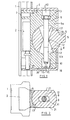
- Figure 1 is broken off the side view of a wall bar 1 shown, which is designed as a profile and can be attached either directly or at a distance in front of a wall.
- the wall rod 1 along a slider 2 can be moved, which is supported with rollers 3 or sliding blocks on the profile and stops in any position. Details of the slider 2 are not shown, since they are known per se.
- the bearing 4 contains in the slider 2, a bearing shell 6, which is integrally formed and in its central region has an opening 7, the surface 17 is a surface of revolution having a circular cross-section. The circle extends over about 3/4 of a circular arc.
- the bearing shell surface 17 of the bearing shell 6 and the rotation surface 9 of the condyle 8 naturally have a common axis of rotation which simultaneously forms the axis of rotation about which the condyle 8 and thus the articulated arm 5 can be rotated.
- the condyle 8 also has an opening 11, the longitudinal axis of which is offset from the point of attachment of the articulated arm 5 in the sectional plane of FIG. 1 by approximately 90 °.
- the opening 11 has a narrowest point 12, which lies in the middle between the two outer ends of the opening 11.
- the screw 12 corresponds to the width and the thickness of the opening 11 the diameter of a screw 12 which is inserted through the bore 10 and the opening 11 therethrough.
- the screw 12 includes a screw head 13, on the other hand, the screw 12 is screwed into a nut 14, to the rotation of a drive recess 15 is provided which points away from the screw 12.
- the aperture 11 diverges in a shape corresponding to a wedge.
- the side walls 16 of the aperture 11 thus extend in a straight line.
- the condyle 8 and with him the articulated arm 5 can be pivoted clockwise until the side wall 16 of the aperture 12 comes to rest on the shank of the screw.
- the aperture 11 is formed symmetrically on both sides of the narrowest point 12, then the side walls 16 are above and below the middle part of the shaft of the screw 12 at. This concern forms a limitation of the angle of rotation by which the articulated arm 5 can be pivoted.
- FIG. 1 likewise shows that a housing in the form of a cover 18 is present around the bearing shell 6, covering the entire bearing shell with the exception of an opening 19.
- the opening 19 is required so that the articulated arm 5 has sufficient space for its pivoting.
- the cover 18 In extension of the drive recess 15 of the nut 14, the cover 18 has an opening 20, can be intervened by the with a tool in the screw drive recess 15.
- FIG. 2 shows a cross section through the arrangement of FIG. 1 below the narrowest point 12 of the condyle 8.
- both the bearing surface 17 of the bearing shell 6 and the voltage applied to her rotation surface 9 of the condyle 8 are part of a spherical surface.
- the condyle 9 can therefore not only be perpendicular to the plane of the drawing of FIG extending axis of rotation to be pivoted, but also about an axis perpendicular to the paper plane of Figure 2 extending axis, which coincides in this case with the longitudinal axis of the screw 12.
- the width of the aperture 11 forming slot measured in Figure 2 from top to bottom, corresponds approximately to the outer diameter of the screw 12.
- the condyle 8 can be pivoted about the screw 12 around, so in addition to the pivoting about a vertical to the screw 12 extending axis.
- the shaft 12 prevents the condyle 8 can be rotated about an axis extending from left to right in Figure 2. But this could also be achieved if the aperture 11 diverges not only in the sectional plane of Figure 1, but also in the sectional plane of Figure 2, so instead of a double wedge a double cone would be formed.
- the screw 12 which is shown in Figure 1, here has a triple function. On the one hand, it forms the axis about which a pivoting of the articulated arm 5 can take place. Moreover, it forms, together with the side walls 16 of the opening 11, a pivoting angle limitation during pivoting in the sectional plane of FIG. 1.
- the third object is to effect the tensioning of the two arms 6 a, 6 b of the bearing shell 6.
- the tension of the two arms 6 a, 6 b of the bearing shell 6 could also take place on both sides of the condyle 8.
- the rotation angle limit and the rotation axis formation could also be done by each arm 6 a, 6 b would project a pin into the opening 11, without the two pins would be connected to each other.
- the condyle 8 is not designed as a full ball but as a spherical disc with two parallel ones Outer surfaces 21.
- the bearing shell 6 is formed as a disc member with parallel side surfaces, which coincide in the illustration of Figure 2 with the side surfaces 21 of the condyle 8.
- Figure 3 shows in a smaller detail the arrangement of the slider 2 with the bearing contained in it on a wall rod, which protrudes from the wall bar 1 facing away from the front side 22 of the cover 18 of the articulated arm 5.
- a cone holder 23 is arranged for the handle of a hand shower.
Landscapes
- Health & Medical Sciences (AREA)
- Life Sciences & Earth Sciences (AREA)
- Engineering & Computer Science (AREA)
- Hydrology & Water Resources (AREA)
- Public Health (AREA)
- Water Supply & Treatment (AREA)
- Pivots And Pivotal Connections (AREA)
- Prostheses (AREA)
Applications Claiming Priority (1)
| Application Number | Priority Date | Filing Date | Title |
|---|---|---|---|
| DE200610038355 DE102006038355A1 (de) | 2006-08-10 | 2006-08-10 | Gelenkhalterung |
Publications (3)
| Publication Number | Publication Date |
|---|---|
| EP1887151A2 true EP1887151A2 (fr) | 2008-02-13 |
| EP1887151A3 EP1887151A3 (fr) | 2009-02-25 |
| EP1887151B1 EP1887151B1 (fr) | 2015-06-03 |
Family
ID=38621035
Family Applications (1)
| Application Number | Title | Priority Date | Filing Date |
|---|---|---|---|
| EP07015046.1A Active EP1887151B1 (fr) | 2006-08-10 | 2007-08-01 | Support angulaire |
Country Status (4)
| Country | Link |
|---|---|
| EP (1) | EP1887151B1 (fr) |
| CN (1) | CN101201075B (fr) |
| DE (1) | DE102006038355A1 (fr) |
| ES (1) | ES2544817T3 (fr) |
Families Citing this family (2)
| Publication number | Priority date | Publication date | Assignee | Title |
|---|---|---|---|---|
| DE102018209985B4 (de) * | 2018-06-20 | 2025-08-14 | Hansgrohe Se | Stangenmontierbare Halterung |
| DE102022114907A1 (de) | 2022-06-14 | 2023-12-14 | Ledlenser GmbH & Co. KG | Kugelgelenk |
Citations (1)
| Publication number | Priority date | Publication date | Assignee | Title |
|---|---|---|---|---|
| DE7717732U1 (de) | 1977-06-04 | 1977-09-22 | Heinrich Rueschenbaum Metallschlauchfabrik, 5860 Iserlohn | Wandhalter fuer eine handbrause |
Family Cites Families (13)
| Publication number | Priority date | Publication date | Assignee | Title |
|---|---|---|---|---|
| FR962397A (fr) * | 1943-04-09 | 1950-06-09 | ||
| DE936903C (de) * | 1953-03-29 | 1955-12-22 | Gerhard Fieseler | Kreuzgelenk zur horizontalen und vertikalen Verschwenkbarkeit eines eine Leuchte od. dgl. tragenden Armes |
| DE1741852U (de) * | 1955-05-25 | 1957-03-21 | Flora Mannesmann | Gelenkverbindung, insbesondere fuer stative. |
| FR1227350A (fr) * | 1959-02-28 | 1960-08-19 | Antenne de voiture | |
| DE1489255A1 (de) * | 1964-11-26 | 1969-08-14 | Josef Laubrunn | Vorrichtung zum Verschieben und Festellen von Gegenstaenden in axialer oder radialer Richtung an einer feststehenden Fuehrungssaeule |
| GB1186882A (en) * | 1967-02-14 | 1970-04-08 | Crosweller & Co Ltd W | Improvements in Fittings for Mounting Accessories on Walls and Like Supports |
| CH651609A5 (en) * | 1981-03-23 | 1985-09-30 | Karrer Weber & Cie Ag | Articulated shower holder |
| DE4333913C2 (de) * | 1992-10-09 | 1997-11-20 | Link Johs Sonor Gmbh | Einstellvorrichtung an längen- und/oder neigungsverstellbaren Haltern, insbesondere für Percussions-Musikinstrumente |
| CH687337A5 (fr) * | 1994-03-22 | 1996-11-15 | Similor Sa | Support de douche mural réglable. |
| US5632049A (en) * | 1996-01-25 | 1997-05-27 | Chen; Te-Sen | Holder assembly for a shower head |
| CN2404637Y (zh) * | 1999-12-15 | 2000-11-08 | 陈宣灿 | 通用调角半球装置 |
| DE10059212A1 (de) * | 2000-11-29 | 2002-06-13 | Grohe Armaturen Friedrich | Brausehaltevorrichtung |
| DE102004052275A1 (de) * | 2004-10-27 | 2006-05-24 | Siemens Ag | Teileinheit einer Antriebsvorrichtung |
-
2006
- 2006-08-10 DE DE200610038355 patent/DE102006038355A1/de not_active Withdrawn
-
2007
- 2007-08-01 EP EP07015046.1A patent/EP1887151B1/fr active Active
- 2007-08-01 ES ES07015046.1T patent/ES2544817T3/es active Active
- 2007-08-10 CN CN2007103081922A patent/CN101201075B/zh active Active
Patent Citations (1)
| Publication number | Priority date | Publication date | Assignee | Title |
|---|---|---|---|---|
| DE7717732U1 (de) | 1977-06-04 | 1977-09-22 | Heinrich Rueschenbaum Metallschlauchfabrik, 5860 Iserlohn | Wandhalter fuer eine handbrause |
Also Published As
| Publication number | Publication date |
|---|---|
| CN101201075A (zh) | 2008-06-18 |
| DE102006038355A1 (de) | 2008-02-14 |
| EP1887151A3 (fr) | 2009-02-25 |
| CN101201075B (zh) | 2012-08-29 |
| EP1887151B1 (fr) | 2015-06-03 |
| ES2544817T3 (es) | 2015-09-04 |
Similar Documents
| Publication | Publication Date | Title |
|---|---|---|
| EP3612700B1 (fr) | Paroi de meuble avec un clapet et un corps de meuble et meuble avec une telle paroi de meuble | |
| DE102015003439B3 (de) | Tür- oder Fensterscharnier | |
| EP0259618B1 (fr) | Penture de porte et fenêtre, réglable pendant et après le montage | |
| DE29607447U1 (de) | Auspreßvorrichtung für ein Achstraggelenk und/oder einen Spurstangenkopf | |
| EP3613931B1 (fr) | Module de bande destiné au raccordement mobile par charnière autour d'un axe de charnière d'un battant sur un cadre | |
| WO2001027409A1 (fr) | Palier a bras pour store a bras articule | |
| AT401080B (de) | Halter für die biegemomentfreie lagerung von glasplatten | |
| EP2169163B1 (fr) | Charnière réglable en hauteur | |
| EP1726403A2 (fr) | Levier avec butée reglable en hauteur | |
| WO2009049712A1 (fr) | Fermeture à compression | |
| DE19960432A1 (de) | Scharnier, insbesondere für eine Fahrzeugtür | |
| EP1887151B1 (fr) | Support angulaire | |
| DE9015155U1 (de) | Nibbelmaschine, insbesondere Handnibbelmaschine | |
| EP0215281A2 (fr) | Palier pour un battant de fenêtre, porte ou similaire | |
| DE102015012641B3 (de) | Gelenkverbindung | |
| EP2581536B1 (fr) | Palier d'angle | |
| EP1781881B1 (fr) | Plaque de montage pour fixer de maniere mobile, des charnieres de meubles sur le corps de meubles | |
| EP0729540B1 (fr) | Paumelle de porte ou de fenetre | |
| EP2284342A2 (fr) | Charnière avec surface d'appui encochée | |
| EP0760890B1 (fr) | Charniere en plusieurs parties | |
| DE4405360C2 (de) | Beschlag zur schwenkbaren Befestigung des Flügels einer Tür oder eines Fensters an einem Rahmen | |
| DE19822030A1 (de) | Zweiteiliger Drückerstift | |
| EP1084660B1 (fr) | Dispositif pour l'ajustage vertical de tiroirs de meuble | |
| DE19605574C1 (de) | Beschlag für Türen oder Fenster | |
| DE102019132327B3 (de) | Türbandanordnung |
Legal Events
| Date | Code | Title | Description |
|---|---|---|---|
| PUAI | Public reference made under article 153(3) epc to a published international application that has entered the european phase |
Free format text: ORIGINAL CODE: 0009012 |
|
| AK | Designated contracting states |
Kind code of ref document: A2 Designated state(s): AT BE BG CH CY CZ DE DK EE ES FI FR GB GR HU IE IS IT LI LT LU LV MC MT NL PL PT RO SE SI SK TR |
|
| AX | Request for extension of the european patent |
Extension state: AL BA HR MK YU |
|
| PUAL | Search report despatched |
Free format text: ORIGINAL CODE: 0009013 |
|
| AK | Designated contracting states |
Kind code of ref document: A3 Designated state(s): AT BE BG CH CY CZ DE DK EE ES FI FR GB GR HU IE IS IT LI LT LU LV MC MT NL PL PT RO SE SI SK TR |
|
| AX | Request for extension of the european patent |
Extension state: AL BA HR MK RS |
|
| 17P | Request for examination filed |
Effective date: 20090721 |
|
| AKX | Designation fees paid |
Designated state(s): AT BE BG CH CY CZ DE DK EE ES FI FR GB GR HU IE IS IT LI LT LU LV MC MT NL PL PT RO SE SI SK TR |
|
| RAP1 | Party data changed (applicant data changed or rights of an application transferred) |
Owner name: HANSGROHE SE |
|
| 17Q | First examination report despatched |
Effective date: 20140519 |
|
| GRAP | Despatch of communication of intention to grant a patent |
Free format text: ORIGINAL CODE: EPIDOSNIGR1 |
|
| INTG | Intention to grant announced |
Effective date: 20150109 |
|
| GRAS | Grant fee paid |
Free format text: ORIGINAL CODE: EPIDOSNIGR3 |
|
| GRAA | (expected) grant |
Free format text: ORIGINAL CODE: 0009210 |
|
| AK | Designated contracting states |
Kind code of ref document: B1 Designated state(s): AT BE BG CH CY CZ DE DK EE ES FI FR GB GR HU IE IS IT LI LT LU LV MC MT NL PL PT RO SE SI SK TR |
|
| REG | Reference to a national code |
Ref country code: GB Ref legal event code: FG4D Free format text: NOT ENGLISH |
|
| REG | Reference to a national code |
Ref country code: CH Ref legal event code: EP |
|
| REG | Reference to a national code |
Ref country code: AT Ref legal event code: REF Ref document number: 730014 Country of ref document: AT Kind code of ref document: T Effective date: 20150715 Ref country code: CH Ref legal event code: NV Representative=s name: DR. LUSUARDI AG, CH Ref country code: IE Ref legal event code: FG4D Free format text: LANGUAGE OF EP DOCUMENT: GERMAN |
|
| REG | Reference to a national code |
Ref country code: DE Ref legal event code: R096 Ref document number: 502007013958 Country of ref document: DE Effective date: 20150716 Ref country code: DE Ref legal event code: R096 Ref document number: 502007013958 Country of ref document: DE |
|
| REG | Reference to a national code |
Ref country code: ES Ref legal event code: FG2A Ref document number: 2544817 Country of ref document: ES Kind code of ref document: T3 Effective date: 20150904 |
|
| PG25 | Lapsed in a contracting state [announced via postgrant information from national office to epo] |
Ref country code: FI Free format text: LAPSE BECAUSE OF FAILURE TO SUBMIT A TRANSLATION OF THE DESCRIPTION OR TO PAY THE FEE WITHIN THE PRESCRIBED TIME-LIMIT Effective date: 20150603 Ref country code: LT Free format text: LAPSE BECAUSE OF FAILURE TO SUBMIT A TRANSLATION OF THE DESCRIPTION OR TO PAY THE FEE WITHIN THE PRESCRIBED TIME-LIMIT Effective date: 20150603 |
|
| REG | Reference to a national code |
Ref country code: NL Ref legal event code: MP Effective date: 20150603 |
|
| REG | Reference to a national code |
Ref country code: LT Ref legal event code: MG4D |
|
| PG25 | Lapsed in a contracting state [announced via postgrant information from national office to epo] |
Ref country code: BG Free format text: LAPSE BECAUSE OF FAILURE TO SUBMIT A TRANSLATION OF THE DESCRIPTION OR TO PAY THE FEE WITHIN THE PRESCRIBED TIME-LIMIT Effective date: 20150903 Ref country code: LV Free format text: LAPSE BECAUSE OF FAILURE TO SUBMIT A TRANSLATION OF THE DESCRIPTION OR TO PAY THE FEE WITHIN THE PRESCRIBED TIME-LIMIT Effective date: 20150603 Ref country code: GR Free format text: LAPSE BECAUSE OF FAILURE TO SUBMIT A TRANSLATION OF THE DESCRIPTION OR TO PAY THE FEE WITHIN THE PRESCRIBED TIME-LIMIT Effective date: 20150904 |
|
| PG25 | Lapsed in a contracting state [announced via postgrant information from national office to epo] |
Ref country code: EE Free format text: LAPSE BECAUSE OF FAILURE TO SUBMIT A TRANSLATION OF THE DESCRIPTION OR TO PAY THE FEE WITHIN THE PRESCRIBED TIME-LIMIT Effective date: 20150603 |
|
| PG25 | Lapsed in a contracting state [announced via postgrant information from national office to epo] |
Ref country code: PT Free format text: LAPSE BECAUSE OF FAILURE TO SUBMIT A TRANSLATION OF THE DESCRIPTION OR TO PAY THE FEE WITHIN THE PRESCRIBED TIME-LIMIT Effective date: 20151006 Ref country code: PL Free format text: LAPSE BECAUSE OF FAILURE TO SUBMIT A TRANSLATION OF THE DESCRIPTION OR TO PAY THE FEE WITHIN THE PRESCRIBED TIME-LIMIT Effective date: 20150603 Ref country code: SK Free format text: LAPSE BECAUSE OF FAILURE TO SUBMIT A TRANSLATION OF THE DESCRIPTION OR TO PAY THE FEE WITHIN THE PRESCRIBED TIME-LIMIT Effective date: 20150603 Ref country code: IS Free format text: LAPSE BECAUSE OF FAILURE TO SUBMIT A TRANSLATION OF THE DESCRIPTION OR TO PAY THE FEE WITHIN THE PRESCRIBED TIME-LIMIT Effective date: 20151003 Ref country code: CZ Free format text: LAPSE BECAUSE OF FAILURE TO SUBMIT A TRANSLATION OF THE DESCRIPTION OR TO PAY THE FEE WITHIN THE PRESCRIBED TIME-LIMIT Effective date: 20150603 Ref country code: RO Free format text: LAPSE BECAUSE OF NON-PAYMENT OF DUE FEES Effective date: 20150603 |
|
| REG | Reference to a national code |
Ref country code: DE Ref legal event code: R097 Ref document number: 502007013958 Country of ref document: DE |
|
| PG25 | Lapsed in a contracting state [announced via postgrant information from national office to epo] |
Ref country code: MC Free format text: LAPSE BECAUSE OF FAILURE TO SUBMIT A TRANSLATION OF THE DESCRIPTION OR TO PAY THE FEE WITHIN THE PRESCRIBED TIME-LIMIT Effective date: 20150603 Ref country code: LU Free format text: LAPSE BECAUSE OF FAILURE TO SUBMIT A TRANSLATION OF THE DESCRIPTION OR TO PAY THE FEE WITHIN THE PRESCRIBED TIME-LIMIT Effective date: 20150801 |
|
| PLBE | No opposition filed within time limit |
Free format text: ORIGINAL CODE: 0009261 |
|
| STAA | Information on the status of an ep patent application or granted ep patent |
Free format text: STATUS: NO OPPOSITION FILED WITHIN TIME LIMIT |
|
| PG25 | Lapsed in a contracting state [announced via postgrant information from national office to epo] |
Ref country code: DK Free format text: LAPSE BECAUSE OF FAILURE TO SUBMIT A TRANSLATION OF THE DESCRIPTION OR TO PAY THE FEE WITHIN THE PRESCRIBED TIME-LIMIT Effective date: 20150603 |
|
| 26N | No opposition filed |
Effective date: 20160304 |
|
| PG25 | Lapsed in a contracting state [announced via postgrant information from national office to epo] |
Ref country code: SI Free format text: LAPSE BECAUSE OF FAILURE TO SUBMIT A TRANSLATION OF THE DESCRIPTION OR TO PAY THE FEE WITHIN THE PRESCRIBED TIME-LIMIT Effective date: 20150603 |
|
| REG | Reference to a national code |
Ref country code: IE Ref legal event code: MM4A |
|
| PG25 | Lapsed in a contracting state [announced via postgrant information from national office to epo] |
Ref country code: IE Free format text: LAPSE BECAUSE OF NON-PAYMENT OF DUE FEES Effective date: 20150801 |
|
| REG | Reference to a national code |
Ref country code: FR Ref legal event code: PLFP Year of fee payment: 10 |
|
| REG | Reference to a national code |
Ref country code: AT Ref legal event code: MM01 Ref document number: 730014 Country of ref document: AT Kind code of ref document: T Effective date: 20150801 |
|
| PG25 | Lapsed in a contracting state [announced via postgrant information from national office to epo] |
Ref country code: AT Free format text: LAPSE BECAUSE OF NON-PAYMENT OF DUE FEES Effective date: 20150801 |
|
| PG25 | Lapsed in a contracting state [announced via postgrant information from national office to epo] |
Ref country code: MT Free format text: LAPSE BECAUSE OF FAILURE TO SUBMIT A TRANSLATION OF THE DESCRIPTION OR TO PAY THE FEE WITHIN THE PRESCRIBED TIME-LIMIT Effective date: 20150603 |
|
| PG25 | Lapsed in a contracting state [announced via postgrant information from national office to epo] |
Ref country code: HU Free format text: LAPSE BECAUSE OF FAILURE TO SUBMIT A TRANSLATION OF THE DESCRIPTION OR TO PAY THE FEE WITHIN THE PRESCRIBED TIME-LIMIT; INVALID AB INITIO Effective date: 20070801 |
|
| PG25 | Lapsed in a contracting state [announced via postgrant information from national office to epo] |
Ref country code: NL Free format text: LAPSE BECAUSE OF FAILURE TO SUBMIT A TRANSLATION OF THE DESCRIPTION OR TO PAY THE FEE WITHIN THE PRESCRIBED TIME-LIMIT Effective date: 20150603 Ref country code: CY Free format text: LAPSE BECAUSE OF FAILURE TO SUBMIT A TRANSLATION OF THE DESCRIPTION OR TO PAY THE FEE WITHIN THE PRESCRIBED TIME-LIMIT Effective date: 20150603 Ref country code: SE Free format text: LAPSE BECAUSE OF FAILURE TO SUBMIT A TRANSLATION OF THE DESCRIPTION OR TO PAY THE FEE WITHIN THE PRESCRIBED TIME-LIMIT Effective date: 20150603 |
|
| PG25 | Lapsed in a contracting state [announced via postgrant information from national office to epo] |
Ref country code: BE Free format text: LAPSE BECAUSE OF NON-PAYMENT OF DUE FEES Effective date: 20150831 |
|
| REG | Reference to a national code |
Ref country code: FR Ref legal event code: PLFP Year of fee payment: 11 |
|
| PG25 | Lapsed in a contracting state [announced via postgrant information from national office to epo] |
Ref country code: TR Free format text: LAPSE BECAUSE OF FAILURE TO SUBMIT A TRANSLATION OF THE DESCRIPTION OR TO PAY THE FEE WITHIN THE PRESCRIBED TIME-LIMIT Effective date: 20150603 |
|
| REG | Reference to a national code |
Ref country code: FR Ref legal event code: PLFP Year of fee payment: 12 |
|
| PGFP | Annual fee paid to national office [announced via postgrant information from national office to epo] |
Ref country code: CH Payment date: 20210713 Year of fee payment: 15 |
|
| PGFP | Annual fee paid to national office [announced via postgrant information from national office to epo] |
Ref country code: GB Payment date: 20220726 Year of fee payment: 16 |
|
| PGFP | Annual fee paid to national office [announced via postgrant information from national office to epo] |
Ref country code: FR Payment date: 20220713 Year of fee payment: 16 |
|
| REG | Reference to a national code |
Ref country code: CH Ref legal event code: PL |
|
| PG25 | Lapsed in a contracting state [announced via postgrant information from national office to epo] |
Ref country code: LI Free format text: LAPSE BECAUSE OF NON-PAYMENT OF DUE FEES Effective date: 20220831 Ref country code: CH Free format text: LAPSE BECAUSE OF NON-PAYMENT OF DUE FEES Effective date: 20220831 |
|
| GBPC | Gb: european patent ceased through non-payment of renewal fee |
Effective date: 20230801 |
|
| PG25 | Lapsed in a contracting state [announced via postgrant information from national office to epo] |
Ref country code: GB Free format text: LAPSE BECAUSE OF NON-PAYMENT OF DUE FEES Effective date: 20230801 |
|
| PG25 | Lapsed in a contracting state [announced via postgrant information from national office to epo] |
Ref country code: GB Free format text: LAPSE BECAUSE OF NON-PAYMENT OF DUE FEES Effective date: 20230801 Ref country code: FR Free format text: LAPSE BECAUSE OF NON-PAYMENT OF DUE FEES Effective date: 20230831 |
|
| PGFP | Annual fee paid to national office [announced via postgrant information from national office to epo] |
Ref country code: ES Payment date: 20240918 Year of fee payment: 18 |
|
| PGFP | Annual fee paid to national office [announced via postgrant information from national office to epo] |
Ref country code: IT Payment date: 20240826 Year of fee payment: 18 |
|
| PGFP | Annual fee paid to national office [announced via postgrant information from national office to epo] |
Ref country code: DE Payment date: 20250827 Year of fee payment: 19 |