EP1887221A2 - Wind turbine and blade pitch angle adjustment device therefor - Google Patents
Wind turbine and blade pitch angle adjustment device therefor Download PDFInfo
- Publication number
- EP1887221A2 EP1887221A2 EP07011264A EP07011264A EP1887221A2 EP 1887221 A2 EP1887221 A2 EP 1887221A2 EP 07011264 A EP07011264 A EP 07011264A EP 07011264 A EP07011264 A EP 07011264A EP 1887221 A2 EP1887221 A2 EP 1887221A2
- Authority
- EP
- European Patent Office
- Prior art keywords
- spring
- rotor blade
- drive
- spring accumulator
- housing
- Prior art date
- Legal status (The legal status is an assumption and is not a legal conclusion. Google has not performed a legal analysis and makes no representation as to the accuracy of the status listed.)
- Granted
Links
Images

Classifications
-
- F—MECHANICAL ENGINEERING; LIGHTING; HEATING; WEAPONS; BLASTING
- F03—MACHINES OR ENGINES FOR LIQUIDS; WIND, SPRING, OR WEIGHT MOTORS; PRODUCING MECHANICAL POWER OR A REACTIVE PROPULSIVE THRUST, NOT OTHERWISE PROVIDED FOR
- F03D—WIND MOTORS
- F03D7/00—Controlling wind motors
- F03D7/02—Controlling wind motors the wind motors having rotation axis substantially parallel to the air flow entering the rotor
- F03D7/022—Adjusting aerodynamic properties of the blades
- F03D7/0224—Adjusting blade pitch
-
- F—MECHANICAL ENGINEERING; LIGHTING; HEATING; WEAPONS; BLASTING
- F03—MACHINES OR ENGINES FOR LIQUIDS; WIND, SPRING, OR WEIGHT MOTORS; PRODUCING MECHANICAL POWER OR A REACTIVE PROPULSIVE THRUST, NOT OTHERWISE PROVIDED FOR
- F03D—WIND MOTORS
- F03D80/00—Details, components or accessories not provided for in groups F03D1/00 - F03D17/00
-
- F—MECHANICAL ENGINEERING; LIGHTING; HEATING; WEAPONS; BLASTING
- F03—MACHINES OR ENGINES FOR LIQUIDS; WIND, SPRING, OR WEIGHT MOTORS; PRODUCING MECHANICAL POWER OR A REACTIVE PROPULSIVE THRUST, NOT OTHERWISE PROVIDED FOR
- F03D—WIND MOTORS
- F03D80/00—Details, components or accessories not provided for in groups F03D1/00 - F03D17/00
- F03D80/70—Bearing or lubricating arrangements
-
- Y—GENERAL TAGGING OF NEW TECHNOLOGICAL DEVELOPMENTS; GENERAL TAGGING OF CROSS-SECTIONAL TECHNOLOGIES SPANNING OVER SEVERAL SECTIONS OF THE IPC; TECHNICAL SUBJECTS COVERED BY FORMER USPC CROSS-REFERENCE ART COLLECTIONS [XRACs] AND DIGESTS
- Y02—TECHNOLOGIES OR APPLICATIONS FOR MITIGATION OR ADAPTATION AGAINST CLIMATE CHANGE
- Y02E—REDUCTION OF GREENHOUSE GAS [GHG] EMISSIONS, RELATED TO ENERGY GENERATION, TRANSMISSION OR DISTRIBUTION
- Y02E10/00—Energy generation through renewable energy sources
- Y02E10/70—Wind energy
- Y02E10/72—Wind turbines with rotation axis in wind direction
Definitions
- the present invention relates to a wind turbine with a rotor having rotatably mounted rotor blades on a rotor color.
- the invention relates to a rotor blade adjustment drive for adjusting the angle of attack of the rotor blades of such a wind turbine, with a drive train which can be connected on the output side to the rotor blade and / or a bearing part carrying the rotor blade, and to a spring accumulator which can be connected to the drive train and which has a spring-loaded shaft Spring storage housing and a spring device which can be tensioned by rotating the spring accumulator shaft and spring accumulator housing relative to each other, wherein the spring accumulator shaft and / or the spring accumulator housing for biasing the spring means from the drive train can be uncoupled and rotatable relative thereto.
- the individual rotor blades can be connected via large bearings rotatably connected to the rotor color, so that the rotor blades can be rotated about its longitudinal axis and thus adjusted in their angle of attack.
- To adjust the rotor blades are mostly electric drive motors used, which adjust the rotatable ring of the rotor blade bearing and thus the rotor blades themselves via a gear and a driven pinion.
- the spring-loaded shaft is connected by means of a coupling with the drive train of the Rotorblattverstellantriebs.
- the springs of the spring accumulator when improper handling hit back uncontrollably and injure the operator with the Aufziehwerkmaschine.
- the object of the present invention is to provide an improved wind turbine of the type mentioned and an improved rotor blade adjustment drive for this purpose, avoiding the disadvantages of the prior art and further developing the latter in an advantageous manner.
- an easy-to-use spring store is to be created, which can be biased without risk of injury and excludes uncontrolled repulse when improper handling.
- a brake device which brakes the spring storage shaft and / or the spring accumulator housing in the uncoupled state during pretensioning of the spring accumulator against the resulting spring preload and / or holds.
- the brake device inhibits an uncontrolled return of the spring-loaded shaft and / or the spring-loaded housing, which would arise in dissolved from the drive train spring accumulator housing or dissolved spring accumulator shaft, for example, if the Aufziehwerkmaschinemaschine would slip off.
- the spring accumulator is preferably designed such that the spring device is designed to be tensioned when the spring accumulator shaft is engaged.
- the spring-loaded housing is rotatably supported by a rotary bearing on a drive train carrier part, preferably releasable locking means for locking the spring accumulator housing are provided in at least one predetermined rotational position relative to the drive train carrier.
- the spring storage housing has over the spring storage shaft a larger lever when mounting the spring means, whereby the Aufziehvorgang can be accomplished with smaller forces.
- the spring accumulator housing usually has a cheaper attack surface to set a suitable device for mounting.
- the braking device is advantageously provided between the spring-loaded housing and the drive-train carrier in a development of the invention.
- the brake device keeps the spring accumulator housing on the drive train carrier or brakes the spring accumulator housing with respect to this, when the locking of the spring accumulator housing is dissolved for the purpose of winding.
- the braking device is designed such that it securely holds the resulting clamping force of the spring device when mounting, but on the other hand, the braking or braking force of the brake can be overcome by the Aufziehstell characteristicn.
- the brake device provides a braking force that is greater than a biasing force of the spring device and smaller than a vorvorbare actuation force for biasing the spring accumulator.
- the braking device can in principle be designed differently, for example, a magnetic, preferably permanent magnetic brake could be provided.
- the spring-loaded housing may preferably be located on the front side on a rotary bearing ring connected to the drive train carrier, wherein advantageously the braking device is arranged radially within said rotary bearing ring.
- the braking device acts advantageously on the one hand on the rotary bearing ring and on the other hand on the spring accumulator housing.
- the brake device can have corresponding brake parts, one of which is fastened to the aforementioned rotary bearing ring and one to the spring-loaded housing.
- the braking device can provide a substantially constant braking force in development of the invention.
- the braking device also have an adjustment for adjusting the braking force to receive in the desired manner on the one hand when mounting the spring accumulator, the spring accumulator housing against the resulting bias, on the other hand, however, allow the mounting itself.
- the brake device is designed in the manner mentioned as a spring-biased friction brake, the spring tension can be adjustable, for example, by means of an adjustment screw. Basically, however, that a braking device with a constant, preset braking force is sufficient.
- a drive means for rotatably driving the spring accumulator housing relative to the drive train is provided in a further development of the invention.
- the spring accumulator needs to be rotationally released so that it can be rotated for mounting the spring accumulator. The rotational movement itself is then accomplished by the drive device.
- the drive device is designed for this purpose in particular as a rotary drive.
- This rotary drive can be mounted on the drive train carrier, opposite which the spring accumulator housing is rotatable.
- the rotary drive can have a drive wheel which can be brought into engagement with the spring-loaded housing.
- a rotation angle and / or speed detection device for detecting the rotation of the spring accumulator housing is provided in the uncoupled state in the development of the invention for checking.
- the rotational angle and / or rotational speed detection device can form a counter, which is advantageously designed to be non-recoverable, so that it always indicates the AufziehTalk the spring accumulator. This is also important for the reverse relaxation of the spring accumulator, for example in case of repair.
- the rotation angle and / or speed detection device can also be used to control the aforementioned Aufziehantrieb, for example, to the extent that this is disabled or turned off when the maximum allowable AufziehCloudes.
- the spring accumulator can in principle be arranged at different points of the drive train or coupled thereto.
- the drive train itself can in principle have a preferably electric drive motor and a transmission connected to the drive motor, wherein advantageously the spring accumulator can be coupled to a transmission element, in particular a transmission shaft of said transmission.
- the arrangement of the drive train components can be chosen basically different.
- An advantageous embodiment may consist in that the drive motor is arranged transversely to said transmission shaft of the transmission and with this, for example via a bevel gear is engaged.
- the spring accumulator can advantageously be arranged with its spring storage shaft parallel, preferably coaxial with the transmission shaft.
- Said gear shaft can in this case drive a drive element, which can be brought into engagement with the associated rotor blade or a bearing part carrying the rotor blade.
- the spring accumulator shaft may be provided between the spring accumulator shaft and the aforementioned transmission, in particular its transmission shaft disengageable clutch through which the spring accumulator shaft can be disconnected, for example, to be able to decouple the spring accumulator completely from the Rotorblattverstellantrieb in case of repair.
- the rotor blade adjustment drive 1 shown in the figures comprises a drive motor 1 shown only schematically, which can be an electric motor and is part of a drive train 2, which has a transmission 3 connected downstream of the drive motor 1.
- the drive motor 1 drives with its output shaft to an input element of the transmission 3, the output side drives a driven pinion 4, which rotates the rotor blade of a wind turbine not shown in detail.
- said driven pinion 4 can in particular be in engagement with the rotatable ring of a large bearing to which the rotor blade is fastened.
- the transmission 3 is formed in the illustrated embodiment as an angle gear in which the input axis extends transversely to the output axis.
- the drive motor 1 drives via a bevel gear 5 a transversely to the axis of rotation of the drive motor 1 extending gear shaft 6, on which the aforementioned output gear 4 is seated.
- a spring accumulator 7 is connected to the drive train 2, which sits in the illustrated embodiment on a drive pinion 4 opposite end face of the transmission 3.
- the spring accumulator comprises, as shown in FIG. 2, a central spring accumulator shaft 8, which is rotatably mounted in a spring accumulator housing 9 and a Feder immediately herein and extends coaxially to the aforementioned transmission shaft 6 in the illustrated embodiment and rotatably coupled with this.
- a disengageable coupling 11 is provided between the spring accumulator shaft 8 and the transmission shaft 6, which is actuated in the illustrated embodiment by an axial recess in the spring accumulator shaft 8 by an actuator 12 at the opposite end of the spring accumulator shaft 8.
- the detachable with a transmission housing 17 spring accumulator housing 9 is formed closed in the illustrated embodiment and has a substantially cylindrical shape. It is understood, however, that the spring accumulator housing 10 does not necessarily have to form a closed housing, but optionally also may be open or may form only a spring-loaded carrier. However, the closed training shown is preferred.
- a spring device 13 in the form of a plurality of coil springs 14 is provided between the spring accumulator shaft 8 and the spring accumulator housing 9, a spring device 13 in the form of a plurality of coil springs 14 is provided. By rotating the spring accumulator shaft 8 and spring accumulator housing 9 relative to each other, said spring means 13 can be mounted so that the supported on the spring accumulator housing 9 generates a torque on the spring accumulator shaft 8 or vice versa.
- the spring-loaded housing 9 is seated with an end-side connection section 15 on a drive train carrier 16, which in the illustrated embodiment is formed by an end-side connection section of the transmission housing 17.
- the spring accumulator housing 9 is rotatably mounted on the transmission housing 17, and that about an axis coaxial to the spring accumulator shaft 8 axis.
- the rotary bearing 18 provided for this purpose comprises in the illustrated embodiment a rotary bearing ring 19, which is secured by screws 20 fixed to the front-side connection portion of the transmission housing 17.
- a pivot bearing ring 21 cooperates, which is fixed to the spring-loaded housing 9.
- the pivot bearing ring 19 is arranged and supported in a corresponding recess 22 in the front-side connection portion 15 of the spring accumulator housing 9, where it is held by the rotary bearing ring 21 which engages over it.
- the aforementioned gear fixed rotary bearing ring 19 can be rotationally locked by releasable locking means 23 in the form of bolts 24 on the spring memory housing 9. In order to rotate the spring housing 9 relative to the gear housing 17, said bolts 24 are removed; In addition, it may be necessary to loosen the pivot bearing ring 21 by loosening him holding screws 25.
- a braking device 26 is provided between the spring accumulator housing 9 and the gear housing 17 which is arranged in the illustrated embodiment radially within the gear fixed pivot bearing ring 19 and a spring housing fixed brake part and a gear housing or having a rotary bearing ring resistant brake part.
- the braking device 26 is formed as a friction brake.
- a brake disk 27 or brake disks runs between two brake shoes, which are biased by a brake spring device 28.
- the braking device 26 is dimensioned so that it can on the one hand hold the bias forces applied by the coil springs 14, on the other hand, however, allows a mounting of the spring accumulator 7 by rotating the spring accumulator housing 9 with a predetermined winding force.
- a Aufziehantrieb 29 is provided which is mounted on the transmission housing 17 and has a drive wheel 30 which meshes with a ring gear 31 on the spring accumulator housing 9 to rotate the spring accumulator housing 9 accordingly.
- the Aufziehantrieb 29 can be actuated for example by means of an attachable hand crank.
- a drive unit which can be powered by external energy sources may also be provided, for example in the form of an electric motor.
- a rotational position detection means 32 is provided, which may be associated with the Aufziehantrieb 29, but according to an alternative embodiment of the invention can also detect the rotational position of the spring housing 9 directly.
- the rotational position detection device 32 is advantageously designed as a counter 33 which indicates the respective rotational position and counts the revolutions.
- said counter 33 is not recoverable, so that it always indicates the current AufziehTalk of the spring accumulator 7, which on the one hand Spanning the spring accumulator 7 avoids and on the other hand for the return of the spring accumulator 7 is important.
Landscapes
- Engineering & Computer Science (AREA)
- Mechanical Engineering (AREA)
- Sustainable Development (AREA)
- Sustainable Energy (AREA)
- Chemical & Material Sciences (AREA)
- Combustion & Propulsion (AREA)
- Life Sciences & Earth Sciences (AREA)
- General Engineering & Computer Science (AREA)
- Physics & Mathematics (AREA)
- Fluid Mechanics (AREA)
- Wind Motors (AREA)
- Connection Of Motors, Electrical Generators, Mechanical Devices, And The Like (AREA)
- Devices For Conveying Motion By Means Of Endless Flexible Members (AREA)
Abstract
Die vorliegende Erfindung betrifft einen Rotorblattverstellantrieb zur Verstellung des Anstellwinkels eines Rotorblatts einer Windkraftanlage, mit einem Antriebsstrang (2) der ausgangsseitig mit dem Rotorblatt und/oder einem das Rotorblatt tragenden Lagerteil verbindbar ist, sowie einem mit dem Antriebsstrang (2) verbindbaren Federspeicher (7), der eine Federspeicherwelle (8), ein Federspeichergehäuse (9) sowie eine Federeinrichtung (13) aufweist, die durch Verdrehen von Federspeicherwelle (8) und Federspeichergehäuse (9) relativ zueinander spannbar ist, wobei die Federspeicherwelle (8) und/oder das Federspeichergehäuse (9) zum Vorspannen des Federspeichers (7) vom Antriebsstrang (2) abkuppelbar und gegenüber diesem drehbar ist, wobei eine Bremsvorrichtung (26) zum Abbremsen und/oder Halten der Federspeicherwelle (8) und/oder des Federspeichergehäuses (9) entgegen der Federvorspannung im abgekuppelten Zustand des Federspeichers (7) vorgesehen ist.The present invention relates to a rotor blade adjustment drive for adjusting the angle of attack of a rotor blade of a wind turbine, having a drive train (2) which is connectable on the output side to the rotor blade and / or a bearing member carrying the rotor blade, and to a spring accumulator (7) which can be connected to the drive train (2). which has a spring storage shaft (8), a spring-loaded housing (9) and a spring device (13) which can be tensioned relative to one another by turning the spring-loaded shaft (8) and spring-loaded housing (9), wherein the spring-loaded shaft (8) and / or the spring-loaded housing (9) for biasing the spring accumulator (7) from the drive train (2) uncoupled and is rotatable relative thereto, wherein a braking device (26) for braking and / or holding the spring accumulator shaft (8) and / or the spring accumulator housing (9) against the spring preload is provided in the uncoupled state of the spring accumulator (7).
Description
Die vorliegende Erfindung betrifft eine Windkraftanlage mit einem Rotor, der an einer Rotornarbe verstellbar gelagerte Rotorblätter aufweist. Die Erfindung betrifft dabei insbesondere einen Rotorblattverstellantrieb zur Verstellung des Anstellwinkels der Rotorblätter einer solchen Windkraftanlage, mit einem Antriebsstrang, der ausgangsseitig mit dem Rotorblatt und/oder einem das Rotorblatt tragenden Lagerteil verbindbar ist, sowie einem mit dem Antriebsstrang verbindbaren Federspeicher, der eine Federspeicherwelle, ein Federspeichergehäuse sowie eine Federeinrichtung aufweist, die durch Verdrehen von Federspeicherwelle und Federspeichergehäuse relativ zueinander spannbar ist, wobei die Federspeicherwelle und/oder das Federspeichergehäuse zum Vorspannen der Federeinrichtung vom Antriebsstrang abkuppelbar und gegenüber diesem drehbar ist.The present invention relates to a wind turbine with a rotor having rotatably mounted rotor blades on a rotor color. In particular, the invention relates to a rotor blade adjustment drive for adjusting the angle of attack of the rotor blades of such a wind turbine, with a drive train which can be connected on the output side to the rotor blade and / or a bearing part carrying the rotor blade, and to a spring accumulator which can be connected to the drive train and which has a spring-loaded shaft Spring storage housing and a spring device which can be tensioned by rotating the spring accumulator shaft and spring accumulator housing relative to each other, wherein the spring accumulator shaft and / or the spring accumulator housing for biasing the spring means from the drive train can be uncoupled and rotatable relative thereto.
In Windkraftanlagen wird zur Regelung der Leistung üblicherweise eine Verstellung der Rotorblätter eingesetzt. Dabei können die einzelnen Rotorblätter über große Lager drehbar mit der Rotornarbe verbunden sein, so dass die Rotorblätter um ihre Längsachse gedreht und damit in ihrem Anstellwinkel eingestellt werden können. Zur Verstellung der Rotorblätter werden größtenteils elektrische Antriebsmotoren verwendet, die über ein Getriebe und ein Abtriebsritzel den drehbaren Ring des Rotorblattlagers und damit die Rotorblätter selbst verstellen.In wind turbines usually an adjustment of the rotor blades is used to control the power. In this case, the individual rotor blades can be connected via large bearings rotatably connected to the rotor color, so that the rotor blades can be rotated about its longitudinal axis and thus adjusted in their angle of attack. To adjust the rotor blades are mostly electric drive motors used, which adjust the rotatable ring of the rotor blade bearing and thus the rotor blades themselves via a gear and a driven pinion.
Tritt in der elektrischen Versorgung der Antriebsmotoren eine Unterbrechung oder eine sonstige Störung der Antriebsmotoren ein, müssen aus Sicherheitsgründen die Rotorblätter in eine gefahrlose Position gebracht werden. In vielen Fällen sind hierzu elektrische Batterien vorgesehen, um eine Notversorgung der Antriebsmotoren zu erreichen. Andererseits wurden bereits mechanische Federspeicher vorgeschlagen, um in den genannten Fällen aus Sicherheitsgründen die Rückstellung der Rotorblätter in eine Neutralstellung zu bewirken. Damit diese mechanischen Federspeicher das Verstellen der Rotorblätter bewirken können, ist vor der Inbetriebnahme ein Vorspannen der Federn der Federspeicher erforderlich. Hierzu wurde vorgeschlagen, die innenliegende Federspeicherwelle vom Antriebsstrang abzukuppeln und mit einem geeigneten Werkzeug zu drehen, bis die gewünschte Vorspannung erreicht ist. nach dem Aufbringen der Vorspannung wird die Federspeicherwelle mittels einer Kupplung mit dem Antriebsstrang des Rotorblattverstellantriebs verbunden. Während des genannten Aufziehvorgangs besteht jedoch eine erhebliche Gefahr darin, dass die Federn des Federspeichers bei unsachgemäßer Handhabung unkontrolliert zurückschlagen und den Bediener mit dem Aufziehwerkzeug verletzen.If an interruption or other malfunction of the drive motors occurs in the electrical supply of the drive motors, the rotor blades must be brought into a safe position for safety reasons. In many cases, this electric batteries are provided to achieve emergency power supply of the drive motors. On the other hand, mechanical spring accumulators have already been proposed in order to bring about the provision of the rotor blades in a neutral position in the cases mentioned for safety reasons. For this mechanical spring can cause the adjustment of the rotor blades, a biasing of the springs of the spring accumulator is required before commissioning. For this purpose, it has been proposed to disengage the internal spring-loaded shaft from the drive train and to turn it with a suitable tool until the desired preload is achieved. after applying the bias, the spring-loaded shaft is connected by means of a coupling with the drive train of the Rotorblattverstellantriebs. During the aforementioned Aufziehvorgangs, however, there is a significant risk that the springs of the spring accumulator when improper handling hit back uncontrollably and injure the operator with the Aufziehwerkzeug.
Der vorliegenden Erfindung liegt hiervon ausgehend die Aufgabe zugrunde, eine verbesserte Windkraftanlage der genannten Art sowie einen verbesserten Rotorblattverstellantrieb hierfür zu schaffen, die Nachteile des Standes der Technik vermeiden und letzteren in vorteilhafterweise weiterbilden. Insbesondere soll ein einfach zu bedienender Federspeicher geschaffen werden, der ohne Verletzungsgefahr vorgespannt werden kann und ein unkontrolliertes Zurückschlagen bei unsachgemäßer Handhabung ausschließt.On this basis, the object of the present invention is to provide an improved wind turbine of the type mentioned and an improved rotor blade adjustment drive for this purpose, avoiding the disadvantages of the prior art and further developing the latter in an advantageous manner. In particular, an easy-to-use spring store is to be created, which can be biased without risk of injury and excludes uncontrolled repulse when improper handling.
Erfindungsgemäß wird diese Aufgabe durch einen Rotorblattverstellantrieb gem. Anspruch 1 sowie eine Windkraftanlage gem. Anspruch 19 gelöst. Bevorzugte Ausgestaltung der Erfindungen sind Gegenstand der abhängigen Ansprüche.According to the invention this object is achieved by a Rotorblattverstellantrieb.
Es wird also vorgeschlagen, das beim Vorspannen des Federspeichers gelöste Federspeicherbauteil gegen ein Zurückschlagen durch die entstehende Federkraft zu sichern und der auf dieses gelöste Bauteil nach und nach einwirkenden Federkraft beim Vorspannen einen hemmenden Widerstand entgegenzusetzen. Erfindungsgemäß ist eine Bremsvorrichtung vorgesehen, die die Federspeicherwelle und/oder das Federspeichergehäuse im abgekuppelten Zustand beim Vorspannen des Federspeichers entgegen der dabei entstehenden Federvorspannung abbremst und/oder hält. Die Bremsvorrichtung hemmt also eine unkontrollierte Rückstellung der Federspeicherwelle und/oder des Federspeichergehäuses, die bei vom Antriebsstrang gelösten Federspeichergehäuse bzw. gelöster Federspeicherwelle entstehen würde, wenn beispielsweise das Aufziehwerkzeug abrutschen würde.It is therefore proposed to secure the spring-loaded component released during pretensioning of the spring accumulator against being repelled by the resulting spring force and to counteract the spring force which is gradually applied to this released component during pretensioning, thereby providing an inhibiting resistance. According to the invention, a brake device is provided which brakes the spring storage shaft and / or the spring accumulator housing in the uncoupled state during pretensioning of the spring accumulator against the resulting spring preload and / or holds. Thus, the brake device inhibits an uncontrolled return of the spring-loaded shaft and / or the spring-loaded housing, which would arise in dissolved from the drive train spring accumulator housing or dissolved spring accumulator shaft, for example, if the Aufziehwerkzeug would slip off.
In Weiterbildung der Erfindung ist dabei der Federspeicher vorzugsweise derart ausgebildet, dass die Federeinrichtung bei eingekuppelter Federspeicherwelle spannbar ausgebildet ist. Insbesondere kann im Gegensatz zum Stand der Technik vorgesehen sein, dass zum Spannen der Federeinrichtung nicht mehr die Federspeicherwelle, sondern das Federspeichergehäuse vom Antriebsstrang abgekuppelt und gedreht wird. In Weiterbildung der Erfindung ist hierzu das Federspeichergehäuse durch ein Drehlager an einem Antriebsstrangträgerteil drehbar gelagert, wobei vorzugsweise lösbare Arretiermittel zur Arretierung des Federspeichergehäuses in zumindest einer vorbestimmten Drehstellung gegenüber dem Antriebsstrangträger vorgesehen sind. Durch das Aufziehen des Federspeichers über eine Bewegung des Federspeichergehäuses kann eine beträchtliche Vereinfachung und Erhöhung der Sicherheit beim Aufziehvorgang erreicht werden, gegebenenfalls auch bereits ohne Verwendung der oben genannten Bremsvorrichtung. Das Federspeichergehäuse besitzt gegenüber der Federspeicherwelle einen größeren Hebel beim Aufziehen der Federeinrichtung, wodurch der Aufziehvorgang mit kleineren Kräften bewerkstelligt werden kann. Zum anderen besitzt das Federspeichergehäuse in der Regel eine günstigere Angriffsfläche, um eine geeignete Vorrichtung zum Aufziehen anzusetzen.In a further development of the invention, the spring accumulator is preferably designed such that the spring device is designed to be tensioned when the spring accumulator shaft is engaged. In particular, in contrast to the prior art may be provided that for tensioning the spring means no longer the spring-loaded shaft, but the spring-loaded housing is disconnected from the drive train and rotated. In a further development of the invention for this purpose, the spring-loaded housing is rotatably supported by a rotary bearing on a drive train carrier part, preferably releasable locking means for locking the spring accumulator housing are provided in at least one predetermined rotational position relative to the drive train carrier. By mounting the spring accumulator via a movement of the spring accumulator housing, a considerable simplification and increase in safety during the winding process can be achieved, possibly even without the use of the abovementioned brake device. The spring storage housing has over the spring storage shaft a larger lever when mounting the spring means, whereby the Aufziehvorgang can be accomplished with smaller forces. On the other hand, the spring accumulator housing usually has a cheaper attack surface to set a suitable device for mounting.
Ist das Federspeichergehäuse in der genannten Weise gegenüber dem Antriebsstrangträger verdrehbar, ist in Weiterbildung der Erfindung die Bremsvorrichtung vorteilhafterweise zwischen dem Federspeichergehäuse und dem Antriebsstrangträger vorgesehen. Die Bremsvorrichtung hält das Federspeichergehäuse am Antriebsstrangträger bzw. bremst das Federspeichergehäuse gegenüber diesem, wenn die Arretierung des Federspeichergehäuses zum Zwecke des Aufziehens gelöst ist.If the spring-loaded housing can be rotated in the above-mentioned manner relative to the drive-train carrier, the braking device is advantageously provided between the spring-loaded housing and the drive-train carrier in a development of the invention. The brake device keeps the spring accumulator housing on the drive train carrier or brakes the spring accumulator housing with respect to this, when the locking of the spring accumulator housing is dissolved for the purpose of winding.
Insbesondere ist die Bremsvorrichtung dabei derart ausgebildet, dass sie die entstehende Spannkraft der Federeinrichtung beim Aufziehen sicher hält, andererseits aber die Brems- bzw. Hemmkraft der Bremse von den Aufziehstellkräften überwunden werden kann. Die Bremsvorrichtung stellt eine Bremskraft bereit, die größer ist als eine Vorspannkraft der Federeinrichtung und kleiner ist als eine vorgehbare Betätigungskraft zur Vorspannung des Federspeichers. Die Bremsvorrichtung kann hierbei grundsätzlich verschieden ausgebildet sein, beispielsweise könnte eine magnetische, vorzugsweise permanentmagnetische Bremse vorgesehen sein. Eine bevorzugte Ausführung der Erfindung besteht allerdings darin, dass die Bremsvorrichtung als Reibbremse, insbesondere als eine federvorgespannte Reibbremse ausgebildet ist.In particular, the braking device is designed such that it securely holds the resulting clamping force of the spring device when mounting, but on the other hand, the braking or braking force of the brake can be overcome by the Aufziehstellkräften. The brake device provides a braking force that is greater than a biasing force of the spring device and smaller than a vorvorbare actuation force for biasing the spring accumulator. The braking device can in principle be designed differently, for example, a magnetic, preferably permanent magnetic brake could be provided. A preferred embodiment of the invention, however, is that the braking device is designed as a friction brake, in particular as a spring-biased friction brake.
Um eine geschützte und gleichzeitig kleinbauende Anordnung zu erreichen, kann in Weiterbildung der Erfindung das Federspeichergehäuse vorzugsweise stirnseitig auf einem mit dem Antriebsstrangträger verbundenen Drehlagerkranz sitzen, wobei vorteilhafterweise die Bremsvorrichtung radial innerhalb des genannten Drehlagerkranzes angeordnet ist. Die Bremsvorrichtung greift hierbei vorteilhafterweise einerseits an dem Drehlagerkranz und andererseits an dem Federspeichergehäuse an. Die Bremsvorrichtung kann hierzu entsprechende Bremsenteile aufweisen, von denen eines an dem genannten Drehlagerkranz und eines am Federspeichergehäuse befestigt ist.In order to achieve a protected and at the same time small-sized arrangement, the spring-loaded housing may preferably be located on the front side on a rotary bearing ring connected to the drive train carrier, wherein advantageously the braking device is arranged radially within said rotary bearing ring. The braking device acts advantageously on the one hand on the rotary bearing ring and on the other hand on the spring accumulator housing. For this purpose, the brake device can have corresponding brake parts, one of which is fastened to the aforementioned rotary bearing ring and one to the spring-loaded housing.
Die Bremsvorrichtung kann in Weiterbildung der Erfindung eine im Wesentlichen konstante Bremskraft bereitstellen. Alternativ hierzu kann die Bremsvorrichtung auch eine Einstellvorrichtung zur Einstellung der Bremskraft aufweisen, um in der gewünschten Weise einerseits beim Aufziehen des Federspeichers das Federspeichergehäuse entgegen der entstehenden Vorspannung zu erhalten, andererseits jedoch das Aufziehen selbst zu erlauben. Ist die Bremsvorrichtung in der genannten Weise als federvorgespannte Reibbremse ausgebildet, kann beispielsweise mittels einer Einstellschraube die Federspannung einstellbar sein. Grundsätzlich gilt jedoch, dass eine Bremsvorrichtung mit konstanter, voreingestellter Bremskraft ausreichend ist.The braking device can provide a substantially constant braking force in development of the invention. Alternatively, the braking device Also have an adjustment for adjusting the braking force to receive in the desired manner on the one hand when mounting the spring accumulator, the spring accumulator housing against the resulting bias, on the other hand, however, allow the mounting itself. If the brake device is designed in the manner mentioned as a spring-biased friction brake, the spring tension can be adjustable, for example, by means of an adjustment screw. Basically, however, that a braking device with a constant, preset braking force is sufficient.
Um den Aufziehvorgang zu erleichtern, ist in Weiterbildung der Erfindung eine Antriebseinrichtung zum rotatorischen Antreiben des Federspeichergehäuses gegenüber dem Antriebsstrang vorgesehen. Jedoch braucht zum Aufziehen des Federspeichers lediglich der Federspeicher rotatorisch gelöst werden, so dass er verdreht werden kann. Die Drehbewegung selbst wird dann von der Antriebsvorrichtung bewerkstelligt.In order to facilitate the Aufziehvorgang, a drive means for rotatably driving the spring accumulator housing relative to the drive train is provided in a further development of the invention. However, only the spring accumulator needs to be rotationally released so that it can be rotated for mounting the spring accumulator. The rotational movement itself is then accomplished by the drive device.
Die Antriebseinrichtung ist hierzu insbesondere als Drehantrieb ausgebildet. Dieser Drehantrieb kann an dem Antriebsstrangträger gelagert sein, gegenüber dem das Federspeichergehäuse verdrehbar ist. Der Drehantrieb kann ein Antriebsrad aufweisen, welches mit dem Federspeichergehäuse in Engriff bringbar ist.The drive device is designed for this purpose in particular as a rotary drive. This rotary drive can be mounted on the drive train carrier, opposite which the spring accumulator housing is rotatable. The rotary drive can have a drive wheel which can be brought into engagement with the spring-loaded housing.
Damit der Aufziehvorgang im zulässigen Bereich bleibt, ist in Weiterbildung der Erfindung zur Kontrolle eine Drehwinkel- und/oder Drehzahlerfassungseinrichtung zur Erfassung der Verdrehung des Federspeichergehäuses im entkuppelten Zustand vorgesehen. Die Drehwinkel- und/oder Drehzahlerfassungseinrichtung kann dabei einen Zähler bilden, der vorteilhafterweise unrückstellbar ausgebildet ist, so dass er immer den Aufziehzustand des Federspeichers anzeigt. Dies ist auch für das umgekehrte Entspannen des Federspeichers beispielsweise im Reparaturfall von Bedeutung. In Weiterbildung der Erfindung kann die Drehwinkel- und/oder Drehzahlerfassungseinrichtung auch dazu benutzt werden, den vorgenannten Aufziehantrieb zu steuern, beispielsweise dahingehend, dass dieser bei Erreichen des maximal zugelassenen Aufziehzustandes gesperrt oder abgeschaltet wird.Thus, the Aufziehvorgang remains within the permissible range, a rotation angle and / or speed detection device for detecting the rotation of the spring accumulator housing is provided in the uncoupled state in the development of the invention for checking. The rotational angle and / or rotational speed detection device can form a counter, which is advantageously designed to be non-recoverable, so that it always indicates the Aufziehzustand the spring accumulator. This is also important for the reverse relaxation of the spring accumulator, for example in case of repair. In a further development of the invention, the rotation angle and / or speed detection device can also be used to control the aforementioned Aufziehantrieb, for example, to the extent that this is disabled or turned off when the maximum allowable Aufziehzustandes.
Der Federspeicher kann grundsätzlich an verschiedener Stelle des Antriebsstranges angeordnet bzw. mit diesem gekoppelt sein. Der Antriebsstrang selbst kann grundsätzlich einen vorzugsweise elektrischen Antriebsmotor sowie ein mit dem Antriebsmotor verbundenes Getriebe aufweisen, wobei vorteilhafterweise der Federspeicher mit einem Getriebeelement, insbesondere einer Getriebewelle des genannten Getriebes kuppelbar ist. Die Anordnung der Antriebsstrangkomponenten kann hierzu grundsätzlich verschieden gewählt sein. Eine vorteilhafte Ausführung kann darin bestehen, dass der Antriebsmotor quer zu der genannten Getriebewelle des Getriebes angeordnet und mit dieser beispielsweise über eine Kegelradverzahnung in Eingriff steht. Bei dieser quer ausgerichteten Anordnung des Antriebsmotors kann der Federspeicher vorteilhafterweise mit seiner Federspeicherwelle parallel, vorzugsweise koaxial zu der Getriebewelle angeordnet sein. Die genannte Getriebewelle kann hierbei ein Antriebselement antreiben, das mit dem zugehörigen Rotorblatt bzw. einem das Rotorblatt tragendem Lagerteil in Eingriff bringbar ist.The spring accumulator can in principle be arranged at different points of the drive train or coupled thereto. The drive train itself can in principle have a preferably electric drive motor and a transmission connected to the drive motor, wherein advantageously the spring accumulator can be coupled to a transmission element, in particular a transmission shaft of said transmission. The arrangement of the drive train components can be chosen basically different. An advantageous embodiment may consist in that the drive motor is arranged transversely to said transmission shaft of the transmission and with this, for example via a bevel gear is engaged. In this transversely oriented arrangement of the drive motor, the spring accumulator can advantageously be arranged with its spring storage shaft parallel, preferably coaxial with the transmission shaft. Said gear shaft can in this case drive a drive element, which can be brought into engagement with the associated rotor blade or a bearing part carrying the rotor blade.
In Weiterbildung der Erfindung kann zwischen der Federspeicherwelle und dem vorgenannten Getriebe, insbesondere dessen Getriebewelle eine ausrückbare Kupplung vorgesehen sein, durch die die Federspeicherwelle abgekuppelt werden kann, beispielsweise um im Reparaturfall den Federspeicher gänzlich von dem Rotorblattverstellantrieb abkuppeln zu können.In a further development of the invention may be provided between the spring accumulator shaft and the aforementioned transmission, in particular its transmission shaft disengageable clutch through which the spring accumulator shaft can be disconnected, for example, to be able to decouple the spring accumulator completely from the Rotorblattverstellantrieb in case of repair.
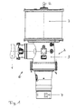
Die vorliegende Erfindung wird nachfolgend anhand eines bevorzugten Ausführungsbeispieles unter zugehörigen Zeichnungen näher erläutert. Die Zeichnungen zeigen:
- Fig. 1:
- Eine schematische Gesamtansicht des Rotorblattverstellantriebs einer Windkraftanlage nach einer bevorzugten Ausführung der Erfindung,
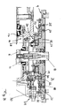
- Fig. 2:
- eine Schnittdarstellung des Rotorblattverstellantriebs aus Fig. 1, und
- Fig. 3:
- eine vergrößerte Schnittansicht der Schnittstelle zwischen dem Federspeicher und dem Getriebe des Rotorblattverstellantriebs aus den vorhergehenden Figuren.
- Fig. 1:
- An overall schematic view of the rotor blade pitch drive of a wind turbine according to a preferred embodiment of the invention,
- Fig. 2:
- a sectional view of the Rotorblattverstellantriebs of Fig. 1, and
- 3:
- an enlarged sectional view of the interface between the spring accumulator and the transmission of the Rotorblattverstellantriebs from the preceding figures.
Der in den Figuren gezeigte Rotorblattverstellantrieb 1 umfasst einen nur schematisch dargestellten Antriebsmotor 1, der ein Elektromotor sein kann und Teil eines Antriebsstranges 2 ist, der ein dem Antriebsmotor 1 nachgeschaltetes Getriebe 3 aufweist. Der Antriebsmotor 1 treibt dabei mit seiner Abtriebswelle ein Eingangselement des Getriebes 3 an, das ausgangsseitig ein Abtriebsritzel 4 antreibt, welches das Rotorblatt einer nicht näher gezeigten Windkraftanlage dreht. Das genannte Abtriebsritzel 4 kann hierzu insbesondere mit dem drehbaren Kranz eines Großlagers in Eingriff stehen, an dem das Rotorblatt befestigt ist.The rotor
Wie Fig. 2 zeigt, ist das Getriebe 3 in der gezeichneten Ausführung als Winkelgetriebe ausgebildet, bei dem sich die Eingangsachse quer zur Ausgangsachse erstreckt. Der Antriebsmotor 1 treibt über eine Kegelradstufe 5 eine sich quer zur Drehachse des Antriebsmotors 1 erstreckende Getriebewelle 6 an, auf der das vorgenannte Abtriebsritzel 4 sitzt.As shown in FIG. 2, the
Weiterhin ist mit dem Antriebsstrang 2 ein Federspeicher 7 verbunden, der in der gezeichneten Ausführung an einer dem Abtriebsritzel 4 gegenüberliegenden Stirnseite des Getriebes 3 sitzt. Der Federspeicher umfasst dabei, wie Fig. 2 zeigt, eine zentrale Federspeicherwelle 8, die in einem Federspeichergehäuse 9 bzw. einem Federspeicherträger drehbar gelagert ist und sich in der gezeichneten Ausführungsform koaxial zu der vorgenannten Getriebewelle 6 erstreckt und mit dieser drehfest kuppelbar ist. Hierzu ist zwischen der Federspeicherwelle 8 und der Getriebewelle 6 eine ausrückbare Kupplung 11 vorgesehen, die in der gezeichneten Ausführung durch eine Axialausnehmung in der Federspeicherwelle 8 hindurch von einem Betätiger 12 am gegenüberliegenden Ende der Federspeicherwelle 8 betätigbar ist. Das mit einem Getriebegehäuse 17 kuppelbare Federspeichergehäuse 9 ist in der gezeichneten Ausführung geschlossen ausgebildet und besitzt eine im Wesentlichen zylindrische Gestalt. Es versteht sich jedoch, dass das Federspeichergehäuse 10 nicht zwangsweise ein geschlossenes Gehäuse bilden muss, sondern gegebenenfalls auch offen ausgebildet sein kann bzw. lediglich einen Federspeicherträger bilden kann. Bevorzugt ist jedoch die gezeigte geschlossene Ausbildung.Furthermore, a
Zwischen der Federspeicherwelle 8 und dem Federspeichergehäuse 9 ist eine Federeinrichtung 13 in Form mehrerer Spiralfedern 14 vorgesehen. Durch Verdrehen von Federspeicherwelle 8 und Federspeichergehäuse 9 relativ zueinander, kann die genannte Federeinrichtung 13 aufgezogen werden, so dass die abgestützt an dem Federspeichergehäuse 9 ein Drehmoment auf der Federspeicherwelle 8 oder umgekehrt erzeugt.Between the
Wie Fig. 3 zeigt, sitzt das Federspeichergehäuse 9 mit einem stirnseitigen Anschlussabschnitt 15 auf einem Antriebstrangträger 16, der in der gezeichneten Ausführung von einem stirnseitigen Anschlussabschnitt des Getriebegehäuses 17 gebildet wird. Das Federspeichergehäuse 9 ist dabei drehbar an dem Getriebegehäuse 17 gelagert, und zwar um eine zur Federspeicherwelle 8 koaxiale Achse. Das hierfür vorgesehene Drehlager 18 umfasst in der gezeichneten Ausführung einen Drehlagerkranz 19, der durch Schrauben 20 fest an dem stirnseitigen Anschlussabschnitt des Getriebegehäuses 17 befestigt ist. Mit dem genannten Drehlagerkranz 19 wirkt ein Drehlagerkranz 21 zusammen, der an dem Federspeichergehäuse 9 befestigt ist. Zudem ist der Drehlagerkranz 19 in einer entsprechenden Ausnehmung 22 in dem stirnseitigen Anschlussabschnitt 15 des Federspeichergehäuses 9 angeordnet und abgestützt, wo er von dem ihn übergreifenden Drehlagerkranz 21 gehalten wird.As shown in FIG. 3, the spring-loaded
Der genannte getriebefeste Drehlagerkranz 19 kann dabei durch lösbare Arretiermittel 23 in Form von Schraubbolzen 24 an dem Federspeichergehäuse 9 rotatorisch arretiert werden. Um das Federspeichergehäuse 9 gegenüber dem Getriebegehäuse 17 drehen zu können, werden die genannten Schraubbolzen 24 entfernt; zudem kann es gegebenenfalls notwendig werden, den Drehlagerkranz 21 durch Lockern der ihn haltenden Schrauben 25 zu lockern.The aforementioned gear fixed
Um ein unkontrolliertes Zurückschlagen des Federspeichergehäuses 9 bei gelöster Drehlagerung zu verhindern, ist zwischen dem Federspeichergehäuse 9 und dem Getriebegehäuse 17 eine Bremsvorrichtung 26 vorgesehen, die in der gezeichneten Ausführung radial innerhalb des getriebefesten Drehlagerkranzes 19 angeordnet ist und ein federspeichergehäusefestes Bremsteil und ein getriebegehäuse- bzw. drehlagerkranzfestes Bremsteil aufweist. In der gezeichneten Ausführung ist die Bremsvorrichtung 26 als Reibebremse ausgebildet. Eine Bremsscheibe 27 bzw. Bremslamellen läuft dabei zwischen zwei Bremsbacken, die durch eine Bremsenfedereinrichtung 28 vorgespannt sind. Die Bremsvorrichtung 26 ist dabei so dimensioniert, dass sie einerseits die von den Spiralfedern 14 aufgebrachten Vorspannkräfte halten kann, andererseits jedoch ein Aufziehen des Federspeichers 7 durch Verdrehen des Federspeichergehäuses 9 mit einer vorbestimmten Aufziehkraft zulässt.In order to prevent uncontrolled repelling of the
Zum Aufziehen des Federspeichers 7 ist ein Aufziehantrieb 29 vorgesehen, der an dem Getriebegehäuse 17 gelagert ist und ein Antriebsrad 30 aufweist, welches mit einem Zahnkranz 31 am Federspeichergehäuse 9 kämmt, um das Federspeichergehäuse 9 entsprechend zu verdrehen. Der Aufziehantrieb 29 kann beispielsweise mittels einer aufsteckbaren Handkurbel betätigt werden. Gegebenenfalls kann jedoch auch eine fremdenergiebetätigbare Antriebseinheit beispielsweise in Form eines Elektromotors vorgesehen sein.For mounting the
Um die jeweils eingestellte Aufziehstellung des Federspeichers 7 zu erfassen, ist eine Drehstellungserfassungseinrichtung 32 vorgesehen, die dem Aufziehantrieb 29 zugeordnet sein kann, jedoch nach einer alternativen Ausführung der Erfindung auch unmittelbar die Drehstellung des Federspeichergehäuses 9 erfassen kann. Die Drehstellungserfassungseinrichtung 32 ist dabei vorteilhafterweise als Zähler 33 ausgebildet, der die jeweilige Drehstellung anzeigt und die Umdrehungen zählt. Vorteilhafterweise ist der genannte Zähler 33 nicht rückstellbar, so dass er stets den aktuellen Aufziehzustand des Federspeichers 7 angibt, was einerseits ein Überspannen des Federspeichers 7 vermeidet und andererseits auch für das Rückstellen des Federspeichers 7 von Bedeutung ist.In order to detect the respectively set Aufziehstellung of the
Claims (19)
Applications Claiming Priority (1)
| Application Number | Priority Date | Filing Date | Title |
|---|---|---|---|
| DE202006012314U DE202006012314U1 (en) | 2006-08-10 | 2006-08-10 | Wind turbine and Rotorblattverstellantrieb this |
Publications (3)
| Publication Number | Publication Date |
|---|---|
| EP1887221A2 true EP1887221A2 (en) | 2008-02-13 |
| EP1887221A3 EP1887221A3 (en) | 2012-12-19 |
| EP1887221B1 EP1887221B1 (en) | 2014-04-16 |
Family
ID=38198255
Family Applications (1)
| Application Number | Title | Priority Date | Filing Date |
|---|---|---|---|
| EP07011264.4A Not-in-force EP1887221B1 (en) | 2006-08-10 | 2007-06-08 | Wind turbine and blade pitch angle adjustment device therefor |
Country Status (9)
| Country | Link |
|---|---|
| US (1) | US7891946B2 (en) |
| EP (1) | EP1887221B1 (en) |
| JP (1) | JP5076113B2 (en) |
| CN (1) | CN101122277B (en) |
| BR (1) | BRPI0703294A (en) |
| CA (1) | CA2593048C (en) |
| DE (1) | DE202006012314U1 (en) |
| DK (1) | DK1887221T3 (en) |
| ES (1) | ES2476802T3 (en) |
Cited By (1)
| Publication number | Priority date | Publication date | Assignee | Title |
|---|---|---|---|---|
| WO2010083724A1 (en) * | 2009-01-21 | 2010-07-29 | Yan Qiang | Brake system for vertical axis wind-powered generator and braking method thereof |
Families Citing this family (11)
| Publication number | Priority date | Publication date | Assignee | Title |
|---|---|---|---|---|
| US8608441B2 (en) | 2006-06-12 | 2013-12-17 | Energyield Llc | Rotatable blade apparatus with individually adjustable blades |
| USD581438S1 (en) * | 2006-08-30 | 2008-11-25 | Tie Tao Liu | Hydraulic mechanism |
| CN101482095B (en) * | 2008-12-04 | 2011-09-28 | 青岛安华新源风电设备有限公司 | Spiral arm tracing mechanical braking system of miniature aerogenerator |
| WO2010119565A1 (en) * | 2009-04-17 | 2010-10-21 | 三菱重工業株式会社 | Pitch driver of wind turbine generator and wind turbine generator |
| DE102009028034A1 (en) * | 2009-07-27 | 2011-02-03 | Robert Bosch Gmbh | Hydraulic master cylinder |
| US10598159B2 (en) | 2016-05-06 | 2020-03-24 | General Electric Company | Wind turbine bearings |
| CN106451326B (en) * | 2016-11-15 | 2018-09-21 | 烟台市华能电器有限公司 | A kind of 10kV distribution lines CT electric power supply control systems |
| DE102018110925A1 (en) * | 2018-05-07 | 2019-11-07 | Liebherr-Components Biberach Gmbh | Actuator for adjusting a slewing bearing |
| CN108590962B (en) * | 2018-06-29 | 2024-04-19 | 北京金风科创风电设备有限公司 | Feathering device, pitch-changing system and pitch-changing method of wind generating set |
| CN109751194B (en) * | 2019-01-25 | 2020-10-27 | 泰州市锋发动力设备有限公司 | A kind of wind power generation device for ship |
| EP3702612A1 (en) * | 2019-02-27 | 2020-09-02 | B&R Industrial Automation GmbH | Method for holding a mobile part of a wind turbine |
Family Cites Families (8)
| Publication number | Priority date | Publication date | Assignee | Title |
|---|---|---|---|---|
| DE4221783C2 (en) * | 1992-07-03 | 1994-06-16 | Klinger Friedrich Prof Dr Ing | Device for adjusting rotor blades |
| DE19720025C5 (en) * | 1997-05-13 | 2008-02-28 | Fritz Fahrner | Drive for angle adjustment of rotor blades in wind turbines |
| EP1029176B1 (en) * | 1997-11-04 | 2004-03-03 | WINDTEC Anlagenerrichtungs- und Consulting GmbH | Windpowerplant |
| JP2003222070A (en) * | 2002-01-30 | 2003-08-08 | Mitsubishi Heavy Ind Ltd | Windmill |
| ES2266833T3 (en) * | 2002-04-26 | 2007-03-01 | General Electric Company | DEVICE FOR ADJUSTING THE ROTOR BLADES OF A WIND ENERGY TURBINE. |
| EP1647708A1 (en) * | 2004-10-14 | 2006-04-19 | General Electric Company | Pitch drive system for a wind turbine |
| JP5062717B2 (en) * | 2006-04-04 | 2012-10-31 | 株式会社日立製作所 | Horizontal axis windmill |
| US7355294B2 (en) * | 2006-05-22 | 2008-04-08 | General Electric Company | Method and system for wind turbine blade movement |
-
2006
- 2006-08-10 DE DE202006012314U patent/DE202006012314U1/en not_active Expired - Lifetime
-
2007
- 2007-06-08 DK DK07011264.4T patent/DK1887221T3/en active
- 2007-06-08 ES ES07011264.4T patent/ES2476802T3/en active Active
- 2007-06-08 EP EP07011264.4A patent/EP1887221B1/en not_active Not-in-force
- 2007-06-28 CA CA2593048A patent/CA2593048C/en not_active Expired - Fee Related
- 2007-07-26 JP JP2007195068A patent/JP5076113B2/en not_active Expired - Fee Related
- 2007-08-08 CN CN2007101380741A patent/CN101122277B/en not_active Expired - Fee Related
- 2007-08-09 BR BRPI0703294-3A patent/BRPI0703294A/en not_active IP Right Cessation
- 2007-08-09 US US11/891,265 patent/US7891946B2/en not_active Expired - Fee Related
Non-Patent Citations (1)
| Title |
|---|
| None |
Cited By (1)
| Publication number | Priority date | Publication date | Assignee | Title |
|---|---|---|---|---|
| WO2010083724A1 (en) * | 2009-01-21 | 2010-07-29 | Yan Qiang | Brake system for vertical axis wind-powered generator and braking method thereof |
Also Published As
| Publication number | Publication date |
|---|---|
| DE202006012314U1 (en) | 2007-12-13 |
| DK1887221T3 (en) | 2014-06-16 |
| US20080056881A1 (en) | 2008-03-06 |
| JP2008045546A (en) | 2008-02-28 |
| BRPI0703294A (en) | 2008-04-01 |
| CN101122277B (en) | 2010-10-13 |
| US7891946B2 (en) | 2011-02-22 |
| EP1887221B1 (en) | 2014-04-16 |
| JP5076113B2 (en) | 2012-11-21 |
| CN101122277A (en) | 2008-02-13 |
| EP1887221A3 (en) | 2012-12-19 |
| CA2593048C (en) | 2010-02-16 |
| ES2476802T3 (en) | 2014-07-15 |
| CA2593048A1 (en) | 2008-02-10 |
Similar Documents
| Publication | Publication Date | Title |
|---|---|---|
| EP1887221B1 (en) | Wind turbine and blade pitch angle adjustment device therefor | |
| DE10031473C1 (en) | Device for rotating a shaft of a wind power plant connected or coupled to a rotor | |
| EP1167755B1 (en) | Locking device for the rotor of a wind turbine | |
| DE102008022383B4 (en) | Positioning of a rotor of a wind energy plant | |
| EP2218908B1 (en) | Wind turbine with a blocking device of a rotor blade | |
| EP2063109B1 (en) | Method for controlling a wind turbine | |
| EP2315943B1 (en) | Adjusting device for adjusting the rotation angle position of the rotor of a wind energy system | |
| DE102008056438B4 (en) | servomotor | |
| DE60305478T2 (en) | DEVICE FOR ADJUSTING A ROTOR BUCKET OF A WIND ENERGY TURBINE | |
| DE102013203678A1 (en) | System for locking the blade adjustment | |
| DE102004046260A1 (en) | Method for operating a device for adjusting a blade pitch and an adjustment | |
| WO2017046194A1 (en) | Planetary gearing for a wind turbine having mounted planetary gears | |
| DE19644705A1 (en) | Wind power generator station turbine rotor-blade setting device | |
| DE102010020355B4 (en) | Locking device for a drive train of a wind turbine | |
| DE2914844C2 (en) | Quick clamping device, in particular for balancing machines for balancing vehicle wheels | |
| DE102018203453B4 (en) | Assembly system for driving a motor vehicle with an electric drive machine | |
| DE102014201465A1 (en) | Modular coupling of a wind turbine gearbox with a generator | |
| DE102022212649A1 (en) | Steering drive for a steering system of a motor vehicle, method for operating a steering drive, steering system for a motor vehicle and method for operating a steering system | |
| DE102007046583A1 (en) | Motorized spindle drive | |
| DE112010004031T5 (en) | Control system for a wind turbine | |
| DE10307929A1 (en) | Rotational structure for a wind-power plant machine-driven gondola has an arrangement of bearings to rotate the gondola on a tower and a drive mechanism to rotate the gondola against the tower | |
| DE102011114247A1 (en) | Rotary drive for a rotor of a wind energy plant | |
| DE19906268A1 (en) | Arrangement for electrically locking steering shaft of steering device of motor vehicle, has housing containing motor which displaces blocking element connected to adapter that absorbs force if shaft is violently twisted | |
| EP2981716B1 (en) | Method and device for coupling and/or decoupling a transmission auxiliary drive, wind turbine | |
| DE102011080972B4 (en) | Locking device |
Legal Events
| Date | Code | Title | Description |
|---|---|---|---|
| PUAI | Public reference made under article 153(3) epc to a published international application that has entered the european phase |
Free format text: ORIGINAL CODE: 0009012 |
|
| AK | Designated contracting states |
Kind code of ref document: A2 Designated state(s): AT BE BG CH CY CZ DE DK EE ES FI FR GB GR HU IE IS IT LI LT LU LV MC MT NL PL PT RO SE SI SK TR |
|
| AX | Request for extension of the european patent |
Extension state: AL BA HR MK YU |
|
| RAP1 | Party data changed (applicant data changed or rights of an application transferred) |
Owner name: LIEBHERR-COMPONENTS BIBERACH GMBH |
|
| PUAL | Search report despatched |
Free format text: ORIGINAL CODE: 0009013 |
|
| AK | Designated contracting states |
Kind code of ref document: A3 Designated state(s): AT BE BG CH CY CZ DE DK EE ES FI FR GB GR HU IE IS IT LI LT LU LV MC MT NL PL PT RO SE SI SK TR |
|
| AX | Request for extension of the european patent |
Extension state: AL BA HR MK RS |
|
| RIC1 | Information provided on ipc code assigned before grant |
Ipc: F03D 11/00 20060101ALI20121109BHEP Ipc: F03D 7/02 20060101AFI20121109BHEP |
|
| 17P | Request for examination filed |
Effective date: 20130605 |
|
| AKX | Designation fees paid |
Designated state(s): AT BE BG CH CY CZ DE DK EE ES FI FR GB GR HU IE IS IT LI LT LU LV MC MT NL PL PT RO SE SI SK TR |
|
| GRAP | Despatch of communication of intention to grant a patent |
Free format text: ORIGINAL CODE: EPIDOSNIGR1 |
|
| INTG | Intention to grant announced |
Effective date: 20131217 |
|
| GRAS | Grant fee paid |
Free format text: ORIGINAL CODE: EPIDOSNIGR3 |
|
| GRAA | (expected) grant |
Free format text: ORIGINAL CODE: 0009210 |
|
| AK | Designated contracting states |
Kind code of ref document: B1 Designated state(s): AT BE BG CH CY CZ DE DK EE ES FI FR GB GR HU IE IS IT LI LT LU LV MC MT NL PL PT RO SE SI SK TR |
|
| REG | Reference to a national code |
Ref country code: GB Ref legal event code: FG4D Free format text: NOT ENGLISH |
|
| REG | Reference to a national code |
Ref country code: CH Ref legal event code: EP |
|
| REG | Reference to a national code |
Ref country code: AT Ref legal event code: REF Ref document number: 662749 Country of ref document: AT Kind code of ref document: T Effective date: 20140515 |
|
| REG | Reference to a national code |
Ref country code: IE Ref legal event code: FG4D Free format text: LANGUAGE OF EP DOCUMENT: GERMAN |
|
| REG | Reference to a national code |
Ref country code: DE Ref legal event code: R096 Ref document number: 502007012977 Country of ref document: DE Effective date: 20140605 |
|
| REG | Reference to a national code |
Ref country code: DK Ref legal event code: T3 Effective date: 20140610 |
|
| REG | Reference to a national code |
Ref country code: ES Ref legal event code: FG2A Ref document number: 2476802 Country of ref document: ES Kind code of ref document: T3 Effective date: 20140715 |
|
| REG | Reference to a national code |
Ref country code: NL Ref legal event code: VDEP Effective date: 20140416 |
|
| REG | Reference to a national code |
Ref country code: LT Ref legal event code: MG4D |
|
| PG25 | Lapsed in a contracting state [announced via postgrant information from national office to epo] |
Ref country code: CY Free format text: LAPSE BECAUSE OF FAILURE TO SUBMIT A TRANSLATION OF THE DESCRIPTION OR TO PAY THE FEE WITHIN THE PRESCRIBED TIME-LIMIT Effective date: 20140416 Ref country code: IS Free format text: LAPSE BECAUSE OF FAILURE TO SUBMIT A TRANSLATION OF THE DESCRIPTION OR TO PAY THE FEE WITHIN THE PRESCRIBED TIME-LIMIT Effective date: 20140816 Ref country code: NL Free format text: LAPSE BECAUSE OF FAILURE TO SUBMIT A TRANSLATION OF THE DESCRIPTION OR TO PAY THE FEE WITHIN THE PRESCRIBED TIME-LIMIT Effective date: 20140416 Ref country code: LT Free format text: LAPSE BECAUSE OF FAILURE TO SUBMIT A TRANSLATION OF THE DESCRIPTION OR TO PAY THE FEE WITHIN THE PRESCRIBED TIME-LIMIT Effective date: 20140416 Ref country code: GR Free format text: LAPSE BECAUSE OF FAILURE TO SUBMIT A TRANSLATION OF THE DESCRIPTION OR TO PAY THE FEE WITHIN THE PRESCRIBED TIME-LIMIT Effective date: 20140717 Ref country code: BG Free format text: LAPSE BECAUSE OF FAILURE TO SUBMIT A TRANSLATION OF THE DESCRIPTION OR TO PAY THE FEE WITHIN THE PRESCRIBED TIME-LIMIT Effective date: 20140716 Ref country code: FI Free format text: LAPSE BECAUSE OF FAILURE TO SUBMIT A TRANSLATION OF THE DESCRIPTION OR TO PAY THE FEE WITHIN THE PRESCRIBED TIME-LIMIT Effective date: 20140416 |
|
| PG25 | Lapsed in a contracting state [announced via postgrant information from national office to epo] |
Ref country code: SE Free format text: LAPSE BECAUSE OF FAILURE TO SUBMIT A TRANSLATION OF THE DESCRIPTION OR TO PAY THE FEE WITHIN THE PRESCRIBED TIME-LIMIT Effective date: 20140416 Ref country code: LV Free format text: LAPSE BECAUSE OF FAILURE TO SUBMIT A TRANSLATION OF THE DESCRIPTION OR TO PAY THE FEE WITHIN THE PRESCRIBED TIME-LIMIT Effective date: 20140416 Ref country code: PL Free format text: LAPSE BECAUSE OF FAILURE TO SUBMIT A TRANSLATION OF THE DESCRIPTION OR TO PAY THE FEE WITHIN THE PRESCRIBED TIME-LIMIT Effective date: 20140416 |
|
| PG25 | Lapsed in a contracting state [announced via postgrant information from national office to epo] |
Ref country code: PT Free format text: LAPSE BECAUSE OF FAILURE TO SUBMIT A TRANSLATION OF THE DESCRIPTION OR TO PAY THE FEE WITHIN THE PRESCRIBED TIME-LIMIT Effective date: 20140818 |
|
| REG | Reference to a national code |
Ref country code: DE Ref legal event code: R097 Ref document number: 502007012977 Country of ref document: DE |
|
| PG25 | Lapsed in a contracting state [announced via postgrant information from national office to epo] |
Ref country code: CZ Free format text: LAPSE BECAUSE OF FAILURE TO SUBMIT A TRANSLATION OF THE DESCRIPTION OR TO PAY THE FEE WITHIN THE PRESCRIBED TIME-LIMIT Effective date: 20140416 Ref country code: LU Free format text: LAPSE BECAUSE OF FAILURE TO SUBMIT A TRANSLATION OF THE DESCRIPTION OR TO PAY THE FEE WITHIN THE PRESCRIBED TIME-LIMIT Effective date: 20140608 Ref country code: RO Free format text: LAPSE BECAUSE OF FAILURE TO SUBMIT A TRANSLATION OF THE DESCRIPTION OR TO PAY THE FEE WITHIN THE PRESCRIBED TIME-LIMIT Effective date: 20140416 Ref country code: MC Free format text: LAPSE BECAUSE OF FAILURE TO SUBMIT A TRANSLATION OF THE DESCRIPTION OR TO PAY THE FEE WITHIN THE PRESCRIBED TIME-LIMIT Effective date: 20140416 Ref country code: SK Free format text: LAPSE BECAUSE OF FAILURE TO SUBMIT A TRANSLATION OF THE DESCRIPTION OR TO PAY THE FEE WITHIN THE PRESCRIBED TIME-LIMIT Effective date: 20140416 Ref country code: EE Free format text: LAPSE BECAUSE OF FAILURE TO SUBMIT A TRANSLATION OF THE DESCRIPTION OR TO PAY THE FEE WITHIN THE PRESCRIBED TIME-LIMIT Effective date: 20140416 |
|
| REG | Reference to a national code |
Ref country code: CH Ref legal event code: PL |
|
| PLBE | No opposition filed within time limit |
Free format text: ORIGINAL CODE: 0009261 |
|
| STAA | Information on the status of an ep patent application or granted ep patent |
Free format text: STATUS: NO OPPOSITION FILED WITHIN TIME LIMIT |
|
| 26N | No opposition filed |
Effective date: 20150119 |
|
| REG | Reference to a national code |
Ref country code: IE Ref legal event code: MM4A |
|
| REG | Reference to a national code |
Ref country code: FR Ref legal event code: ST Effective date: 20150227 |
|
| PG25 | Lapsed in a contracting state [announced via postgrant information from national office to epo] |
Ref country code: CH Free format text: LAPSE BECAUSE OF NON-PAYMENT OF DUE FEES Effective date: 20140630 Ref country code: LI Free format text: LAPSE BECAUSE OF NON-PAYMENT OF DUE FEES Effective date: 20140630 Ref country code: IE Free format text: LAPSE BECAUSE OF NON-PAYMENT OF DUE FEES Effective date: 20140608 |
|
| REG | Reference to a national code |
Ref country code: DE Ref legal event code: R097 Ref document number: 502007012977 Country of ref document: DE Effective date: 20150119 |
|
| PG25 | Lapsed in a contracting state [announced via postgrant information from national office to epo] |
Ref country code: FR Free format text: LAPSE BECAUSE OF NON-PAYMENT OF DUE FEES Effective date: 20140630 |
|
| PG25 | Lapsed in a contracting state [announced via postgrant information from national office to epo] |
Ref country code: SI Free format text: LAPSE BECAUSE OF FAILURE TO SUBMIT A TRANSLATION OF THE DESCRIPTION OR TO PAY THE FEE WITHIN THE PRESCRIBED TIME-LIMIT Effective date: 20140416 |
|
| REG | Reference to a national code |
Ref country code: AT Ref legal event code: MM01 Ref document number: 662749 Country of ref document: AT Kind code of ref document: T Effective date: 20140608 |
|
| PG25 | Lapsed in a contracting state [announced via postgrant information from national office to epo] |
Ref country code: AT Free format text: LAPSE BECAUSE OF NON-PAYMENT OF DUE FEES Effective date: 20140608 |
|
| PG25 | Lapsed in a contracting state [announced via postgrant information from national office to epo] |
Ref country code: MT Free format text: LAPSE BECAUSE OF FAILURE TO SUBMIT A TRANSLATION OF THE DESCRIPTION OR TO PAY THE FEE WITHIN THE PRESCRIBED TIME-LIMIT Effective date: 20140416 |
|
| PG25 | Lapsed in a contracting state [announced via postgrant information from national office to epo] |
Ref country code: BE Free format text: LAPSE BECAUSE OF FAILURE TO SUBMIT A TRANSLATION OF THE DESCRIPTION OR TO PAY THE FEE WITHIN THE PRESCRIBED TIME-LIMIT Effective date: 20140630 Ref country code: HU Free format text: LAPSE BECAUSE OF FAILURE TO SUBMIT A TRANSLATION OF THE DESCRIPTION OR TO PAY THE FEE WITHIN THE PRESCRIBED TIME-LIMIT; INVALID AB INITIO Effective date: 20070608 Ref country code: TR Free format text: LAPSE BECAUSE OF FAILURE TO SUBMIT A TRANSLATION OF THE DESCRIPTION OR TO PAY THE FEE WITHIN THE PRESCRIBED TIME-LIMIT Effective date: 20140416 |
|
| PGFP | Annual fee paid to national office [announced via postgrant information from national office to epo] |
Ref country code: ES Payment date: 20160621 Year of fee payment: 10 Ref country code: GB Payment date: 20160623 Year of fee payment: 10 |
|
| PGFP | Annual fee paid to national office [announced via postgrant information from national office to epo] |
Ref country code: DK Payment date: 20160623 Year of fee payment: 10 |
|
| PGFP | Annual fee paid to national office [announced via postgrant information from national office to epo] |
Ref country code: IT Payment date: 20160630 Year of fee payment: 10 |
|
| REG | Reference to a national code |
Ref country code: DK Ref legal event code: EBP Effective date: 20170630 |
|
| GBPC | Gb: european patent ceased through non-payment of renewal fee |
Effective date: 20170608 |
|
| PG25 | Lapsed in a contracting state [announced via postgrant information from national office to epo] |
Ref country code: GB Free format text: LAPSE BECAUSE OF NON-PAYMENT OF DUE FEES Effective date: 20170608 |
|
| PG25 | Lapsed in a contracting state [announced via postgrant information from national office to epo] |
Ref country code: IT Free format text: LAPSE BECAUSE OF NON-PAYMENT OF DUE FEES Effective date: 20170608 |
|
| PG25 | Lapsed in a contracting state [announced via postgrant information from national office to epo] |
Ref country code: DK Free format text: LAPSE BECAUSE OF NON-PAYMENT OF DUE FEES Effective date: 20170630 |
|
| REG | Reference to a national code |
Ref country code: ES Ref legal event code: FD2A Effective date: 20181116 |
|
| PG25 | Lapsed in a contracting state [announced via postgrant information from national office to epo] |
Ref country code: ES Free format text: LAPSE BECAUSE OF NON-PAYMENT OF DUE FEES Effective date: 20170609 |
|
| PGFP | Annual fee paid to national office [announced via postgrant information from national office to epo] |
Ref country code: DE Payment date: 20210628 Year of fee payment: 15 |
|
| REG | Reference to a national code |
Ref country code: DE Ref legal event code: R119 Ref document number: 502007012977 Country of ref document: DE |
|
| PG25 | Lapsed in a contracting state [announced via postgrant information from national office to epo] |
Ref country code: DE Free format text: LAPSE BECAUSE OF NON-PAYMENT OF DUE FEES Effective date: 20230103 |