EP1887221A2 - Eolienne et dispositif de réglage du pas de l'hélice pour éolienne - Google Patents
Eolienne et dispositif de réglage du pas de l'hélice pour éolienne Download PDFInfo
- Publication number
- EP1887221A2 EP1887221A2 EP07011264A EP07011264A EP1887221A2 EP 1887221 A2 EP1887221 A2 EP 1887221A2 EP 07011264 A EP07011264 A EP 07011264A EP 07011264 A EP07011264 A EP 07011264A EP 1887221 A2 EP1887221 A2 EP 1887221A2
- Authority
- EP
- European Patent Office
- Prior art keywords
- spring
- rotor blade
- drive
- spring accumulator
- housing
- Prior art date
- Legal status (The legal status is an assumption and is not a legal conclusion. Google has not performed a legal analysis and makes no representation as to the accuracy of the status listed.)
- Granted
Links
Images

Classifications
-
- F—MECHANICAL ENGINEERING; LIGHTING; HEATING; WEAPONS; BLASTING
- F03—MACHINES OR ENGINES FOR LIQUIDS; WIND, SPRING, OR WEIGHT MOTORS; PRODUCING MECHANICAL POWER OR A REACTIVE PROPULSIVE THRUST, NOT OTHERWISE PROVIDED FOR
- F03D—WIND MOTORS
- F03D7/00—Controlling wind motors
- F03D7/02—Controlling wind motors the wind motors having rotation axis substantially parallel to the air flow entering the rotor
- F03D7/022—Adjusting aerodynamic properties of the blades
- F03D7/0224—Adjusting blade pitch
-
- F—MECHANICAL ENGINEERING; LIGHTING; HEATING; WEAPONS; BLASTING
- F03—MACHINES OR ENGINES FOR LIQUIDS; WIND, SPRING, OR WEIGHT MOTORS; PRODUCING MECHANICAL POWER OR A REACTIVE PROPULSIVE THRUST, NOT OTHERWISE PROVIDED FOR
- F03D—WIND MOTORS
- F03D80/00—Details, components or accessories not provided for in groups F03D1/00 - F03D17/00
- F03D80/70—Bearing or lubricating arrangements
-
- Y—GENERAL TAGGING OF NEW TECHNOLOGICAL DEVELOPMENTS; GENERAL TAGGING OF CROSS-SECTIONAL TECHNOLOGIES SPANNING OVER SEVERAL SECTIONS OF THE IPC; TECHNICAL SUBJECTS COVERED BY FORMER USPC CROSS-REFERENCE ART COLLECTIONS [XRACs] AND DIGESTS
- Y02—TECHNOLOGIES OR APPLICATIONS FOR MITIGATION OR ADAPTATION AGAINST CLIMATE CHANGE
- Y02E—REDUCTION OF GREENHOUSE GAS [GHG] EMISSIONS, RELATED TO ENERGY GENERATION, TRANSMISSION OR DISTRIBUTION
- Y02E10/00—Energy generation through renewable energy sources
- Y02E10/70—Wind energy
- Y02E10/72—Wind turbines with rotation axis in wind direction
Definitions
- the present invention relates to a wind turbine with a rotor having rotatably mounted rotor blades on a rotor color.
- the invention relates to a rotor blade adjustment drive for adjusting the angle of attack of the rotor blades of such a wind turbine, with a drive train which can be connected on the output side to the rotor blade and / or a bearing part carrying the rotor blade, and to a spring accumulator which can be connected to the drive train and which has a spring-loaded shaft Spring storage housing and a spring device which can be tensioned by rotating the spring accumulator shaft and spring accumulator housing relative to each other, wherein the spring accumulator shaft and / or the spring accumulator housing for biasing the spring means from the drive train can be uncoupled and rotatable relative thereto.
- the individual rotor blades can be connected via large bearings rotatably connected to the rotor color, so that the rotor blades can be rotated about its longitudinal axis and thus adjusted in their angle of attack.
- To adjust the rotor blades are mostly electric drive motors used, which adjust the rotatable ring of the rotor blade bearing and thus the rotor blades themselves via a gear and a driven pinion.
- the spring-loaded shaft is connected by means of a coupling with the drive train of the Rotorblattverstellantriebs.
- the springs of the spring accumulator when improper handling hit back uncontrollably and injure the operator with the Aufziehwerkmaschine.
- the object of the present invention is to provide an improved wind turbine of the type mentioned and an improved rotor blade adjustment drive for this purpose, avoiding the disadvantages of the prior art and further developing the latter in an advantageous manner.
- an easy-to-use spring store is to be created, which can be biased without risk of injury and excludes uncontrolled repulse when improper handling.
- a brake device which brakes the spring storage shaft and / or the spring accumulator housing in the uncoupled state during pretensioning of the spring accumulator against the resulting spring preload and / or holds.
- the brake device inhibits an uncontrolled return of the spring-loaded shaft and / or the spring-loaded housing, which would arise in dissolved from the drive train spring accumulator housing or dissolved spring accumulator shaft, for example, if the Aufziehwerkmaschinemaschine would slip off.
- the spring accumulator is preferably designed such that the spring device is designed to be tensioned when the spring accumulator shaft is engaged.
- the spring-loaded housing is rotatably supported by a rotary bearing on a drive train carrier part, preferably releasable locking means for locking the spring accumulator housing are provided in at least one predetermined rotational position relative to the drive train carrier.
- the spring storage housing has over the spring storage shaft a larger lever when mounting the spring means, whereby the Aufziehvorgang can be accomplished with smaller forces.
- the spring accumulator housing usually has a cheaper attack surface to set a suitable device for mounting.
- the braking device is advantageously provided between the spring-loaded housing and the drive-train carrier in a development of the invention.
- the brake device keeps the spring accumulator housing on the drive train carrier or brakes the spring accumulator housing with respect to this, when the locking of the spring accumulator housing is dissolved for the purpose of winding.
- the braking device is designed such that it securely holds the resulting clamping force of the spring device when mounting, but on the other hand, the braking or braking force of the brake can be overcome by the Aufziehstell characteristicn.
- the brake device provides a braking force that is greater than a biasing force of the spring device and smaller than a vorvorbare actuation force for biasing the spring accumulator.
- the braking device can in principle be designed differently, for example, a magnetic, preferably permanent magnetic brake could be provided.
- the spring-loaded housing may preferably be located on the front side on a rotary bearing ring connected to the drive train carrier, wherein advantageously the braking device is arranged radially within said rotary bearing ring.
- the braking device acts advantageously on the one hand on the rotary bearing ring and on the other hand on the spring accumulator housing.
- the brake device can have corresponding brake parts, one of which is fastened to the aforementioned rotary bearing ring and one to the spring-loaded housing.
- the braking device can provide a substantially constant braking force in development of the invention.
- the braking device also have an adjustment for adjusting the braking force to receive in the desired manner on the one hand when mounting the spring accumulator, the spring accumulator housing against the resulting bias, on the other hand, however, allow the mounting itself.
- the brake device is designed in the manner mentioned as a spring-biased friction brake, the spring tension can be adjustable, for example, by means of an adjustment screw. Basically, however, that a braking device with a constant, preset braking force is sufficient.
- a drive means for rotatably driving the spring accumulator housing relative to the drive train is provided in a further development of the invention.
- the spring accumulator needs to be rotationally released so that it can be rotated for mounting the spring accumulator. The rotational movement itself is then accomplished by the drive device.
- the drive device is designed for this purpose in particular as a rotary drive.
- This rotary drive can be mounted on the drive train carrier, opposite which the spring accumulator housing is rotatable.
- the rotary drive can have a drive wheel which can be brought into engagement with the spring-loaded housing.
- a rotation angle and / or speed detection device for detecting the rotation of the spring accumulator housing is provided in the uncoupled state in the development of the invention for checking.
- the rotational angle and / or rotational speed detection device can form a counter, which is advantageously designed to be non-recoverable, so that it always indicates the AufziehTalk the spring accumulator. This is also important for the reverse relaxation of the spring accumulator, for example in case of repair.
- the rotation angle and / or speed detection device can also be used to control the aforementioned Aufziehantrieb, for example, to the extent that this is disabled or turned off when the maximum allowable AufziehCloudes.
- the spring accumulator can in principle be arranged at different points of the drive train or coupled thereto.
- the drive train itself can in principle have a preferably electric drive motor and a transmission connected to the drive motor, wherein advantageously the spring accumulator can be coupled to a transmission element, in particular a transmission shaft of said transmission.
- the arrangement of the drive train components can be chosen basically different.
- An advantageous embodiment may consist in that the drive motor is arranged transversely to said transmission shaft of the transmission and with this, for example via a bevel gear is engaged.
- the spring accumulator can advantageously be arranged with its spring storage shaft parallel, preferably coaxial with the transmission shaft.
- Said gear shaft can in this case drive a drive element, which can be brought into engagement with the associated rotor blade or a bearing part carrying the rotor blade.
- the spring accumulator shaft may be provided between the spring accumulator shaft and the aforementioned transmission, in particular its transmission shaft disengageable clutch through which the spring accumulator shaft can be disconnected, for example, to be able to decouple the spring accumulator completely from the Rotorblattverstellantrieb in case of repair.
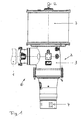
- the rotor blade adjustment drive 1 shown in the figures comprises a drive motor 1 shown only schematically, which can be an electric motor and is part of a drive train 2, which has a transmission 3 connected downstream of the drive motor 1.
- the drive motor 1 drives with its output shaft to an input element of the transmission 3, the output side drives a driven pinion 4, which rotates the rotor blade of a wind turbine not shown in detail.
- said driven pinion 4 can in particular be in engagement with the rotatable ring of a large bearing to which the rotor blade is fastened.
- the transmission 3 is formed in the illustrated embodiment as an angle gear in which the input axis extends transversely to the output axis.
- the drive motor 1 drives via a bevel gear 5 a transversely to the axis of rotation of the drive motor 1 extending gear shaft 6, on which the aforementioned output gear 4 is seated.
- a spring accumulator 7 is connected to the drive train 2, which sits in the illustrated embodiment on a drive pinion 4 opposite end face of the transmission 3.
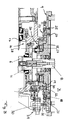
- the spring accumulator comprises, as shown in FIG. 2, a central spring accumulator shaft 8, which is rotatably mounted in a spring accumulator housing 9 and a Feder immediately herein and extends coaxially to the aforementioned transmission shaft 6 in the illustrated embodiment and rotatably coupled with this.
- a disengageable coupling 11 is provided between the spring accumulator shaft 8 and the transmission shaft 6, which is actuated in the illustrated embodiment by an axial recess in the spring accumulator shaft 8 by an actuator 12 at the opposite end of the spring accumulator shaft 8.
- the detachable with a transmission housing 17 spring accumulator housing 9 is formed closed in the illustrated embodiment and has a substantially cylindrical shape. It is understood, however, that the spring accumulator housing 10 does not necessarily have to form a closed housing, but optionally also may be open or may form only a spring-loaded carrier. However, the closed training shown is preferred.
- a spring device 13 in the form of a plurality of coil springs 14 is provided between the spring accumulator shaft 8 and the spring accumulator housing 9, a spring device 13 in the form of a plurality of coil springs 14 is provided. By rotating the spring accumulator shaft 8 and spring accumulator housing 9 relative to each other, said spring means 13 can be mounted so that the supported on the spring accumulator housing 9 generates a torque on the spring accumulator shaft 8 or vice versa.
- the spring-loaded housing 9 is seated with an end-side connection section 15 on a drive train carrier 16, which in the illustrated embodiment is formed by an end-side connection section of the transmission housing 17.
- the spring accumulator housing 9 is rotatably mounted on the transmission housing 17, and that about an axis coaxial to the spring accumulator shaft 8 axis.
- the rotary bearing 18 provided for this purpose comprises in the illustrated embodiment a rotary bearing ring 19, which is secured by screws 20 fixed to the front-side connection portion of the transmission housing 17.
- a pivot bearing ring 21 cooperates, which is fixed to the spring-loaded housing 9.
- the pivot bearing ring 19 is arranged and supported in a corresponding recess 22 in the front-side connection portion 15 of the spring accumulator housing 9, where it is held by the rotary bearing ring 21 which engages over it.
- the aforementioned gear fixed rotary bearing ring 19 can be rotationally locked by releasable locking means 23 in the form of bolts 24 on the spring memory housing 9. In order to rotate the spring housing 9 relative to the gear housing 17, said bolts 24 are removed; In addition, it may be necessary to loosen the pivot bearing ring 21 by loosening him holding screws 25.
- a braking device 26 is provided between the spring accumulator housing 9 and the gear housing 17 which is arranged in the illustrated embodiment radially within the gear fixed pivot bearing ring 19 and a spring housing fixed brake part and a gear housing or having a rotary bearing ring resistant brake part.
- the braking device 26 is formed as a friction brake.
- a brake disk 27 or brake disks runs between two brake shoes, which are biased by a brake spring device 28.
- the braking device 26 is dimensioned so that it can on the one hand hold the bias forces applied by the coil springs 14, on the other hand, however, allows a mounting of the spring accumulator 7 by rotating the spring accumulator housing 9 with a predetermined winding force.
- a Aufziehantrieb 29 is provided which is mounted on the transmission housing 17 and has a drive wheel 30 which meshes with a ring gear 31 on the spring accumulator housing 9 to rotate the spring accumulator housing 9 accordingly.
- the Aufziehantrieb 29 can be actuated for example by means of an attachable hand crank.
- a drive unit which can be powered by external energy sources may also be provided, for example in the form of an electric motor.
- a rotational position detection means 32 is provided, which may be associated with the Aufziehantrieb 29, but according to an alternative embodiment of the invention can also detect the rotational position of the spring housing 9 directly.
- the rotational position detection device 32 is advantageously designed as a counter 33 which indicates the respective rotational position and counts the revolutions.
- said counter 33 is not recoverable, so that it always indicates the current AufziehTalk of the spring accumulator 7, which on the one hand Spanning the spring accumulator 7 avoids and on the other hand for the return of the spring accumulator 7 is important.
Landscapes
- Engineering & Computer Science (AREA)
- Chemical & Material Sciences (AREA)
- Life Sciences & Earth Sciences (AREA)
- Sustainable Development (AREA)
- Sustainable Energy (AREA)
- Combustion & Propulsion (AREA)
- Mechanical Engineering (AREA)
- General Engineering & Computer Science (AREA)
- Fluid Mechanics (AREA)
- Physics & Mathematics (AREA)
- Wind Motors (AREA)
- Connection Of Motors, Electrical Generators, Mechanical Devices, And The Like (AREA)
- Devices For Conveying Motion By Means Of Endless Flexible Members (AREA)
Applications Claiming Priority (1)
| Application Number | Priority Date | Filing Date | Title |
|---|---|---|---|
| DE202006012314U DE202006012314U1 (de) | 2006-08-10 | 2006-08-10 | Windkraftanlage sowie Rotorblattverstellantrieb hierfür |
Publications (3)
| Publication Number | Publication Date |
|---|---|
| EP1887221A2 true EP1887221A2 (fr) | 2008-02-13 |
| EP1887221A3 EP1887221A3 (fr) | 2012-12-19 |
| EP1887221B1 EP1887221B1 (fr) | 2014-04-16 |
Family
ID=38198255
Family Applications (1)
| Application Number | Title | Priority Date | Filing Date |
|---|---|---|---|
| EP07011264.4A Not-in-force EP1887221B1 (fr) | 2006-08-10 | 2007-06-08 | Eolienne et dispositif de réglage du pas de l'hélice pour éolienne |
Country Status (9)
| Country | Link |
|---|---|
| US (1) | US7891946B2 (fr) |
| EP (1) | EP1887221B1 (fr) |
| JP (1) | JP5076113B2 (fr) |
| CN (1) | CN101122277B (fr) |
| BR (1) | BRPI0703294A (fr) |
| CA (1) | CA2593048C (fr) |
| DE (1) | DE202006012314U1 (fr) |
| DK (1) | DK1887221T3 (fr) |
| ES (1) | ES2476802T3 (fr) |
Cited By (1)
| Publication number | Priority date | Publication date | Assignee | Title |
|---|---|---|---|---|
| WO2010083724A1 (fr) * | 2009-01-21 | 2010-07-29 | Yan Qiang | Système de freinage pour générateur à axe vertical fonctionnant à l'énergie éolienne et procédé de freinage de celui-ci |
Families Citing this family (11)
| Publication number | Priority date | Publication date | Assignee | Title |
|---|---|---|---|---|
| US8608441B2 (en) | 2006-06-12 | 2013-12-17 | Energyield Llc | Rotatable blade apparatus with individually adjustable blades |
| USD581438S1 (en) * | 2006-08-30 | 2008-11-25 | Tie Tao Liu | Hydraulic mechanism |
| CN101482095B (zh) * | 2008-12-04 | 2011-09-28 | 青岛安华新源风电设备有限公司 | 小型风力发电机旋臂跟踪机械制动系统 |
| BRPI0910319A2 (pt) * | 2009-04-17 | 2015-09-29 | Mitsubishi Heavy Ind Ltd | aparelho de acíonamento por passo de um gerador eólico, e, gerador eólico |
| DE102009028034A1 (de) * | 2009-07-27 | 2011-02-03 | Robert Bosch Gmbh | Hydraulischer Hauptbremszylinder |
| US10598159B2 (en) | 2016-05-06 | 2020-03-24 | General Electric Company | Wind turbine bearings |
| CN106451326B (zh) * | 2016-11-15 | 2018-09-21 | 烟台市华能电器有限公司 | 一种10kV配电线路CT供电控制系统 |
| DE102018110925A1 (de) * | 2018-05-07 | 2019-11-07 | Liebherr-Components Biberach Gmbh | Stellantrieb zum Verstellen eines Großwälzlagers |
| CN108590962B (zh) * | 2018-06-29 | 2024-04-19 | 北京金风科创风电设备有限公司 | 风力发电机组的顺桨装置、变桨系统及其变桨方法 |
| CN109751194B (zh) * | 2019-01-25 | 2020-10-27 | 泰州市锋发动力设备有限公司 | 一种船舶用风力发电装置 |
| EP3702612A1 (fr) | 2019-02-27 | 2020-09-02 | B&R Industrial Automation GmbH | Procédé de maintien d'une partie mobile d'une éolienne |
Family Cites Families (8)
| Publication number | Priority date | Publication date | Assignee | Title |
|---|---|---|---|---|
| DE4221783C2 (de) * | 1992-07-03 | 1994-06-16 | Klinger Friedrich Prof Dr Ing | Vorrichtung zur Verstellung von Rotorblättern |
| DE19720025C5 (de) * | 1997-05-13 | 2008-02-28 | Fritz Fahrner | Antrieb zur Winkelverstellung von Rotorblättern in Windkraftanlagen |
| AU1135199A (en) * | 1997-11-04 | 1999-05-24 | Gerald Hehenberger | Drive mechanism for adjusting the rotor blades of wind power installations |
| JP2003222070A (ja) * | 2002-01-30 | 2003-08-08 | Mitsubishi Heavy Ind Ltd | 風 車 |
| DK1499804T3 (da) * | 2002-04-26 | 2006-09-18 | Gen Electric | Anordning til indstilling af et rotorblad på en vindenergiturbine |
| EP1647708A1 (fr) * | 2004-10-14 | 2006-04-19 | General Electric Company | Système de réglage du pas de l'hélice pour turbine éolienne |
| JP5062717B2 (ja) * | 2006-04-04 | 2012-10-31 | 株式会社日立製作所 | 水平軸風車 |
| US7355294B2 (en) * | 2006-05-22 | 2008-04-08 | General Electric Company | Method and system for wind turbine blade movement |
-
2006
- 2006-08-10 DE DE202006012314U patent/DE202006012314U1/de not_active Expired - Lifetime
-
2007
- 2007-06-08 ES ES07011264.4T patent/ES2476802T3/es active Active
- 2007-06-08 EP EP07011264.4A patent/EP1887221B1/fr not_active Not-in-force
- 2007-06-08 DK DK07011264.4T patent/DK1887221T3/da active
- 2007-06-28 CA CA2593048A patent/CA2593048C/fr not_active Expired - Fee Related
- 2007-07-26 JP JP2007195068A patent/JP5076113B2/ja not_active Expired - Fee Related
- 2007-08-08 CN CN2007101380741A patent/CN101122277B/zh not_active Expired - Fee Related
- 2007-08-09 US US11/891,265 patent/US7891946B2/en not_active Expired - Fee Related
- 2007-08-09 BR BRPI0703294-3A patent/BRPI0703294A/pt not_active IP Right Cessation
Non-Patent Citations (1)
| Title |
|---|
| None |
Cited By (1)
| Publication number | Priority date | Publication date | Assignee | Title |
|---|---|---|---|---|
| WO2010083724A1 (fr) * | 2009-01-21 | 2010-07-29 | Yan Qiang | Système de freinage pour générateur à axe vertical fonctionnant à l'énergie éolienne et procédé de freinage de celui-ci |
Also Published As
| Publication number | Publication date |
|---|---|
| BRPI0703294A (pt) | 2008-04-01 |
| US20080056881A1 (en) | 2008-03-06 |
| EP1887221B1 (fr) | 2014-04-16 |
| CA2593048A1 (fr) | 2008-02-10 |
| US7891946B2 (en) | 2011-02-22 |
| CN101122277B (zh) | 2010-10-13 |
| JP5076113B2 (ja) | 2012-11-21 |
| DE202006012314U1 (de) | 2007-12-13 |
| ES2476802T3 (es) | 2014-07-15 |
| CN101122277A (zh) | 2008-02-13 |
| JP2008045546A (ja) | 2008-02-28 |
| EP1887221A3 (fr) | 2012-12-19 |
| CA2593048C (fr) | 2010-02-16 |
| DK1887221T3 (da) | 2014-06-16 |
Similar Documents
| Publication | Publication Date | Title |
|---|---|---|
| EP1887221B1 (fr) | Eolienne et dispositif de réglage du pas de l'hélice pour éolienne | |
| DE10031473C1 (de) | Vorrichtung zum Drehen einer mit einem Rotor verbundenen oder gekoppelten Welle einer Windkraftanlage | |
| EP1167755B1 (fr) | Dispositif de blocage pour le rotor d'une éolienne | |
| DE102008022383B4 (de) | Positionierung eines Rotors einer Windenergieanlage | |
| EP2218908B1 (fr) | Eolienne avec un dispositif d'arrêt d'une pale | |
| EP2063109B1 (fr) | Procédé de commande d'une éolienne | |
| EP2315943B1 (fr) | Dispositif de réglage destiné à régler la position angulaire du rotor d'une installation éolienne | |
| DE102008056438B4 (de) | Servomotor | |
| DE60305478T2 (de) | Vorrichtung zur einstellung einer rotorschaufel einer windenergieturbine | |
| DE102004046260A1 (de) | Verfahren zum Betreiben einer Vorrichtung zum Verstellen eines Blatteinstellwinkels sowie eine Verstellvorrichtung | |
| DE4221783A1 (de) | Vorrichtung zur Verstellung von Rotorblättern | |
| WO2017046194A1 (fr) | Train planétaire destiné à une éolienne, muni de pignons satellites montés sur palier lisse | |
| DE19644705A1 (de) | Vorrichtung zur Verstellung von Rotorblättern | |
| DE102010020355B4 (de) | Arretiervorrichtung für einen Triebstrang einer Windenergieanlage | |
| DE2914844C2 (de) | Schnellspannvorrichtung, insbesondere für Auswuchtmaschinen zum Auswuchten von Fahrzeugrädern | |
| DE102018203453B4 (de) | Baugruppensystem für den Antrieb eines Kraftfahrzeugs mit elektrischer Antriebsmaschine | |
| DE102014201465A1 (de) | Modulare Kopplung eines Windkraftgetriebes mit einem Generator | |
| DE112010004031T5 (de) | Steuersystem für eine Windkraftanlage | |
| DE102019113780A1 (de) | Montagewerkzeug für eine Montage und/oder eine Demontage eines Elektromotors | |
| DE10307929A1 (de) | Anordnung zur Drehung einer Maschinengondel | |
| DE102011114247A1 (de) | Drehantrieb für einen Rotor einer Windenergieanlage | |
| DE19906268A1 (de) | Vorrichtung zur elektrischen Verriegelung der Lenkspindel einer Lenkeinrichtung | |
| EP2981716B1 (fr) | Procédé et dispositif permettant de coupler et/ou de découpler un entraînement auxiliaire de transmission, éolienne | |
| DE102011080972B4 (de) | Sperreinrichtung | |
| EP1094235B1 (fr) | Dispositif de freinage pour un véhicule |
Legal Events
| Date | Code | Title | Description |
|---|---|---|---|
| PUAI | Public reference made under article 153(3) epc to a published international application that has entered the european phase |
Free format text: ORIGINAL CODE: 0009012 |
|
| AK | Designated contracting states |
Kind code of ref document: A2 Designated state(s): AT BE BG CH CY CZ DE DK EE ES FI FR GB GR HU IE IS IT LI LT LU LV MC MT NL PL PT RO SE SI SK TR |
|
| AX | Request for extension of the european patent |
Extension state: AL BA HR MK YU |
|
| RAP1 | Party data changed (applicant data changed or rights of an application transferred) |
Owner name: LIEBHERR-COMPONENTS BIBERACH GMBH |
|
| PUAL | Search report despatched |
Free format text: ORIGINAL CODE: 0009013 |
|
| AK | Designated contracting states |
Kind code of ref document: A3 Designated state(s): AT BE BG CH CY CZ DE DK EE ES FI FR GB GR HU IE IS IT LI LT LU LV MC MT NL PL PT RO SE SI SK TR |
|
| AX | Request for extension of the european patent |
Extension state: AL BA HR MK RS |
|
| RIC1 | Information provided on ipc code assigned before grant |
Ipc: F03D 11/00 20060101ALI20121109BHEP Ipc: F03D 7/02 20060101AFI20121109BHEP |
|
| 17P | Request for examination filed |
Effective date: 20130605 |
|
| AKX | Designation fees paid |
Designated state(s): AT BE BG CH CY CZ DE DK EE ES FI FR GB GR HU IE IS IT LI LT LU LV MC MT NL PL PT RO SE SI SK TR |
|
| GRAP | Despatch of communication of intention to grant a patent |
Free format text: ORIGINAL CODE: EPIDOSNIGR1 |
|
| INTG | Intention to grant announced |
Effective date: 20131217 |
|
| GRAS | Grant fee paid |
Free format text: ORIGINAL CODE: EPIDOSNIGR3 |
|
| GRAA | (expected) grant |
Free format text: ORIGINAL CODE: 0009210 |
|
| AK | Designated contracting states |
Kind code of ref document: B1 Designated state(s): AT BE BG CH CY CZ DE DK EE ES FI FR GB GR HU IE IS IT LI LT LU LV MC MT NL PL PT RO SE SI SK TR |
|
| REG | Reference to a national code |
Ref country code: GB Ref legal event code: FG4D Free format text: NOT ENGLISH |
|
| REG | Reference to a national code |
Ref country code: CH Ref legal event code: EP |
|
| REG | Reference to a national code |
Ref country code: AT Ref legal event code: REF Ref document number: 662749 Country of ref document: AT Kind code of ref document: T Effective date: 20140515 |
|
| REG | Reference to a national code |
Ref country code: IE Ref legal event code: FG4D Free format text: LANGUAGE OF EP DOCUMENT: GERMAN |
|
| REG | Reference to a national code |
Ref country code: DE Ref legal event code: R096 Ref document number: 502007012977 Country of ref document: DE Effective date: 20140605 |
|
| REG | Reference to a national code |
Ref country code: DK Ref legal event code: T3 Effective date: 20140610 |
|
| REG | Reference to a national code |
Ref country code: ES Ref legal event code: FG2A Ref document number: 2476802 Country of ref document: ES Kind code of ref document: T3 Effective date: 20140715 |
|
| REG | Reference to a national code |
Ref country code: NL Ref legal event code: VDEP Effective date: 20140416 |
|
| REG | Reference to a national code |
Ref country code: LT Ref legal event code: MG4D |
|
| PG25 | Lapsed in a contracting state [announced via postgrant information from national office to epo] |
Ref country code: CY Free format text: LAPSE BECAUSE OF FAILURE TO SUBMIT A TRANSLATION OF THE DESCRIPTION OR TO PAY THE FEE WITHIN THE PRESCRIBED TIME-LIMIT Effective date: 20140416 Ref country code: IS Free format text: LAPSE BECAUSE OF FAILURE TO SUBMIT A TRANSLATION OF THE DESCRIPTION OR TO PAY THE FEE WITHIN THE PRESCRIBED TIME-LIMIT Effective date: 20140816 Ref country code: NL Free format text: LAPSE BECAUSE OF FAILURE TO SUBMIT A TRANSLATION OF THE DESCRIPTION OR TO PAY THE FEE WITHIN THE PRESCRIBED TIME-LIMIT Effective date: 20140416 Ref country code: LT Free format text: LAPSE BECAUSE OF FAILURE TO SUBMIT A TRANSLATION OF THE DESCRIPTION OR TO PAY THE FEE WITHIN THE PRESCRIBED TIME-LIMIT Effective date: 20140416 Ref country code: GR Free format text: LAPSE BECAUSE OF FAILURE TO SUBMIT A TRANSLATION OF THE DESCRIPTION OR TO PAY THE FEE WITHIN THE PRESCRIBED TIME-LIMIT Effective date: 20140717 Ref country code: BG Free format text: LAPSE BECAUSE OF FAILURE TO SUBMIT A TRANSLATION OF THE DESCRIPTION OR TO PAY THE FEE WITHIN THE PRESCRIBED TIME-LIMIT Effective date: 20140716 Ref country code: FI Free format text: LAPSE BECAUSE OF FAILURE TO SUBMIT A TRANSLATION OF THE DESCRIPTION OR TO PAY THE FEE WITHIN THE PRESCRIBED TIME-LIMIT Effective date: 20140416 |
|
| PG25 | Lapsed in a contracting state [announced via postgrant information from national office to epo] |
Ref country code: SE Free format text: LAPSE BECAUSE OF FAILURE TO SUBMIT A TRANSLATION OF THE DESCRIPTION OR TO PAY THE FEE WITHIN THE PRESCRIBED TIME-LIMIT Effective date: 20140416 Ref country code: LV Free format text: LAPSE BECAUSE OF FAILURE TO SUBMIT A TRANSLATION OF THE DESCRIPTION OR TO PAY THE FEE WITHIN THE PRESCRIBED TIME-LIMIT Effective date: 20140416 Ref country code: PL Free format text: LAPSE BECAUSE OF FAILURE TO SUBMIT A TRANSLATION OF THE DESCRIPTION OR TO PAY THE FEE WITHIN THE PRESCRIBED TIME-LIMIT Effective date: 20140416 |
|
| PG25 | Lapsed in a contracting state [announced via postgrant information from national office to epo] |
Ref country code: PT Free format text: LAPSE BECAUSE OF FAILURE TO SUBMIT A TRANSLATION OF THE DESCRIPTION OR TO PAY THE FEE WITHIN THE PRESCRIBED TIME-LIMIT Effective date: 20140818 |
|
| REG | Reference to a national code |
Ref country code: DE Ref legal event code: R097 Ref document number: 502007012977 Country of ref document: DE |
|
| PG25 | Lapsed in a contracting state [announced via postgrant information from national office to epo] |
Ref country code: CZ Free format text: LAPSE BECAUSE OF FAILURE TO SUBMIT A TRANSLATION OF THE DESCRIPTION OR TO PAY THE FEE WITHIN THE PRESCRIBED TIME-LIMIT Effective date: 20140416 Ref country code: LU Free format text: LAPSE BECAUSE OF FAILURE TO SUBMIT A TRANSLATION OF THE DESCRIPTION OR TO PAY THE FEE WITHIN THE PRESCRIBED TIME-LIMIT Effective date: 20140608 Ref country code: RO Free format text: LAPSE BECAUSE OF FAILURE TO SUBMIT A TRANSLATION OF THE DESCRIPTION OR TO PAY THE FEE WITHIN THE PRESCRIBED TIME-LIMIT Effective date: 20140416 Ref country code: MC Free format text: LAPSE BECAUSE OF FAILURE TO SUBMIT A TRANSLATION OF THE DESCRIPTION OR TO PAY THE FEE WITHIN THE PRESCRIBED TIME-LIMIT Effective date: 20140416 Ref country code: SK Free format text: LAPSE BECAUSE OF FAILURE TO SUBMIT A TRANSLATION OF THE DESCRIPTION OR TO PAY THE FEE WITHIN THE PRESCRIBED TIME-LIMIT Effective date: 20140416 Ref country code: EE Free format text: LAPSE BECAUSE OF FAILURE TO SUBMIT A TRANSLATION OF THE DESCRIPTION OR TO PAY THE FEE WITHIN THE PRESCRIBED TIME-LIMIT Effective date: 20140416 |
|
| REG | Reference to a national code |
Ref country code: CH Ref legal event code: PL |
|
| PLBE | No opposition filed within time limit |
Free format text: ORIGINAL CODE: 0009261 |
|
| STAA | Information on the status of an ep patent application or granted ep patent |
Free format text: STATUS: NO OPPOSITION FILED WITHIN TIME LIMIT |
|
| 26N | No opposition filed |
Effective date: 20150119 |
|
| REG | Reference to a national code |
Ref country code: IE Ref legal event code: MM4A |
|
| REG | Reference to a national code |
Ref country code: FR Ref legal event code: ST Effective date: 20150227 |
|
| PG25 | Lapsed in a contracting state [announced via postgrant information from national office to epo] |
Ref country code: CH Free format text: LAPSE BECAUSE OF NON-PAYMENT OF DUE FEES Effective date: 20140630 Ref country code: LI Free format text: LAPSE BECAUSE OF NON-PAYMENT OF DUE FEES Effective date: 20140630 Ref country code: IE Free format text: LAPSE BECAUSE OF NON-PAYMENT OF DUE FEES Effective date: 20140608 |
|
| REG | Reference to a national code |
Ref country code: DE Ref legal event code: R097 Ref document number: 502007012977 Country of ref document: DE Effective date: 20150119 |
|
| PG25 | Lapsed in a contracting state [announced via postgrant information from national office to epo] |
Ref country code: FR Free format text: LAPSE BECAUSE OF NON-PAYMENT OF DUE FEES Effective date: 20140630 |
|
| PG25 | Lapsed in a contracting state [announced via postgrant information from national office to epo] |
Ref country code: SI Free format text: LAPSE BECAUSE OF FAILURE TO SUBMIT A TRANSLATION OF THE DESCRIPTION OR TO PAY THE FEE WITHIN THE PRESCRIBED TIME-LIMIT Effective date: 20140416 |
|
| REG | Reference to a national code |
Ref country code: AT Ref legal event code: MM01 Ref document number: 662749 Country of ref document: AT Kind code of ref document: T Effective date: 20140608 |
|
| PG25 | Lapsed in a contracting state [announced via postgrant information from national office to epo] |
Ref country code: AT Free format text: LAPSE BECAUSE OF NON-PAYMENT OF DUE FEES Effective date: 20140608 |
|
| PG25 | Lapsed in a contracting state [announced via postgrant information from national office to epo] |
Ref country code: MT Free format text: LAPSE BECAUSE OF FAILURE TO SUBMIT A TRANSLATION OF THE DESCRIPTION OR TO PAY THE FEE WITHIN THE PRESCRIBED TIME-LIMIT Effective date: 20140416 |
|
| PG25 | Lapsed in a contracting state [announced via postgrant information from national office to epo] |
Ref country code: BE Free format text: LAPSE BECAUSE OF FAILURE TO SUBMIT A TRANSLATION OF THE DESCRIPTION OR TO PAY THE FEE WITHIN THE PRESCRIBED TIME-LIMIT Effective date: 20140630 Ref country code: HU Free format text: LAPSE BECAUSE OF FAILURE TO SUBMIT A TRANSLATION OF THE DESCRIPTION OR TO PAY THE FEE WITHIN THE PRESCRIBED TIME-LIMIT; INVALID AB INITIO Effective date: 20070608 Ref country code: TR Free format text: LAPSE BECAUSE OF FAILURE TO SUBMIT A TRANSLATION OF THE DESCRIPTION OR TO PAY THE FEE WITHIN THE PRESCRIBED TIME-LIMIT Effective date: 20140416 |
|
| PGFP | Annual fee paid to national office [announced via postgrant information from national office to epo] |
Ref country code: ES Payment date: 20160621 Year of fee payment: 10 Ref country code: GB Payment date: 20160623 Year of fee payment: 10 |
|
| PGFP | Annual fee paid to national office [announced via postgrant information from national office to epo] |
Ref country code: DK Payment date: 20160623 Year of fee payment: 10 |
|
| PGFP | Annual fee paid to national office [announced via postgrant information from national office to epo] |
Ref country code: IT Payment date: 20160630 Year of fee payment: 10 |
|
| REG | Reference to a national code |
Ref country code: DK Ref legal event code: EBP Effective date: 20170630 |
|
| GBPC | Gb: european patent ceased through non-payment of renewal fee |
Effective date: 20170608 |
|
| PG25 | Lapsed in a contracting state [announced via postgrant information from national office to epo] |
Ref country code: GB Free format text: LAPSE BECAUSE OF NON-PAYMENT OF DUE FEES Effective date: 20170608 |
|
| PG25 | Lapsed in a contracting state [announced via postgrant information from national office to epo] |
Ref country code: IT Free format text: LAPSE BECAUSE OF NON-PAYMENT OF DUE FEES Effective date: 20170608 |
|
| PG25 | Lapsed in a contracting state [announced via postgrant information from national office to epo] |
Ref country code: DK Free format text: LAPSE BECAUSE OF NON-PAYMENT OF DUE FEES Effective date: 20170630 |
|
| REG | Reference to a national code |
Ref country code: ES Ref legal event code: FD2A Effective date: 20181116 |
|
| PG25 | Lapsed in a contracting state [announced via postgrant information from national office to epo] |
Ref country code: ES Free format text: LAPSE BECAUSE OF NON-PAYMENT OF DUE FEES Effective date: 20170609 |
|
| PGFP | Annual fee paid to national office [announced via postgrant information from national office to epo] |
Ref country code: DE Payment date: 20210628 Year of fee payment: 15 |
|
| REG | Reference to a national code |
Ref country code: DE Ref legal event code: R119 Ref document number: 502007012977 Country of ref document: DE |
|
| PG25 | Lapsed in a contracting state [announced via postgrant information from national office to epo] |
Ref country code: DE Free format text: LAPSE BECAUSE OF NON-PAYMENT OF DUE FEES Effective date: 20230103 |