EP1887273A2 - Appareil de support pour dispositifs de visualisation et dispositif de visualisation le comprenant - Google Patents
Appareil de support pour dispositifs de visualisation et dispositif de visualisation le comprenant Download PDFInfo
- Publication number
- EP1887273A2 EP1887273A2 EP07111119A EP07111119A EP1887273A2 EP 1887273 A2 EP1887273 A2 EP 1887273A2 EP 07111119 A EP07111119 A EP 07111119A EP 07111119 A EP07111119 A EP 07111119A EP 1887273 A2 EP1887273 A2 EP 1887273A2
- Authority
- EP
- European Patent Office
- Prior art keywords
- curved
- plug
- elastic member
- main body
- display device
- Prior art date
- Legal status (The legal status is an assumption and is not a legal conclusion. Google has not performed a legal analysis and makes no representation as to the accuracy of the status listed.)
- Withdrawn
Links
Images


Classifications
-
- F—MECHANICAL ENGINEERING; LIGHTING; HEATING; WEAPONS; BLASTING
- F16—ENGINEERING ELEMENTS AND UNITS; GENERAL MEASURES FOR PRODUCING AND MAINTAINING EFFECTIVE FUNCTIONING OF MACHINES OR INSTALLATIONS; THERMAL INSULATION IN GENERAL
- F16M—FRAMES, CASINGS OR BEDS OF ENGINES, MACHINES OR APPARATUS, NOT SPECIFIC TO ENGINES, MACHINES OR APPARATUS PROVIDED FOR ELSEWHERE; STANDS; SUPPORTS
- F16M11/00—Stands or trestles as supports for apparatus or articles placed thereon ; Stands for scientific apparatus such as gravitational force meters
- F16M11/02—Heads
- F16M11/04—Means for attachment of apparatus; Means allowing adjustment of the apparatus relatively to the stand
- F16M11/06—Means for attachment of apparatus; Means allowing adjustment of the apparatus relatively to the stand allowing pivoting
- F16M11/12—Means for attachment of apparatus; Means allowing adjustment of the apparatus relatively to the stand allowing pivoting in more than one direction
- F16M11/14—Means for attachment of apparatus; Means allowing adjustment of the apparatus relatively to the stand allowing pivoting in more than one direction with ball-joint
-
- F—MECHANICAL ENGINEERING; LIGHTING; HEATING; WEAPONS; BLASTING
- F16—ENGINEERING ELEMENTS AND UNITS; GENERAL MEASURES FOR PRODUCING AND MAINTAINING EFFECTIVE FUNCTIONING OF MACHINES OR INSTALLATIONS; THERMAL INSULATION IN GENERAL
- F16M—FRAMES, CASINGS OR BEDS OF ENGINES, MACHINES OR APPARATUS, NOT SPECIFIC TO ENGINES, MACHINES OR APPARATUS PROVIDED FOR ELSEWHERE; STANDS; SUPPORTS
- F16M11/00—Stands or trestles as supports for apparatus or articles placed thereon ; Stands for scientific apparatus such as gravitational force meters
- F16M11/02—Heads
- F16M11/04—Means for attachment of apparatus; Means allowing adjustment of the apparatus relatively to the stand
- F16M11/06—Means for attachment of apparatus; Means allowing adjustment of the apparatus relatively to the stand allowing pivoting
- F16M11/10—Means for attachment of apparatus; Means allowing adjustment of the apparatus relatively to the stand allowing pivoting around a horizontal axis
-
- F—MECHANICAL ENGINEERING; LIGHTING; HEATING; WEAPONS; BLASTING
- F16—ENGINEERING ELEMENTS AND UNITS; GENERAL MEASURES FOR PRODUCING AND MAINTAINING EFFECTIVE FUNCTIONING OF MACHINES OR INSTALLATIONS; THERMAL INSULATION IN GENERAL
- F16M—FRAMES, CASINGS OR BEDS OF ENGINES, MACHINES OR APPARATUS, NOT SPECIFIC TO ENGINES, MACHINES OR APPARATUS PROVIDED FOR ELSEWHERE; STANDS; SUPPORTS
- F16M2200/00—Details of stands or supports
- F16M2200/08—Foot or support base
-
- Y—GENERAL TAGGING OF NEW TECHNOLOGICAL DEVELOPMENTS; GENERAL TAGGING OF CROSS-SECTIONAL TECHNOLOGIES SPANNING OVER SEVERAL SECTIONS OF THE IPC; TECHNICAL SUBJECTS COVERED BY FORMER USPC CROSS-REFERENCE ART COLLECTIONS [XRACs] AND DIGESTS
- Y10—TECHNICAL SUBJECTS COVERED BY FORMER USPC
- Y10S—TECHNICAL SUBJECTS COVERED BY FORMER USPC CROSS-REFERENCE ART COLLECTIONS [XRACs] AND DIGESTS
- Y10S248/00—Supports
- Y10S248/917—Video display screen support
- Y10S248/919—Adjustably orientable video screen support
- Y10S248/922—Angular
- Y10S248/923—Tilting
Definitions
- the present invention relates generally to a supporting apparatus for display devices, and more particularly to a supporting apparatus for display devices, capable of supporting a main body and adjusting the viewing angle of a display screen of the main body, and a display device having the same.
- a display device such as a liquid crystal display (LCD) or a plasma display panel (PDP) is provided with a supporting apparatus, which supports a main body and simultaneously adjusts the viewing angle of a display screen of the main body so as to use it on a table such as a desk.
- a supporting apparatus for display devices is disclosed in Korean Patent Application Publication No. 2006-74206 (July 3, 2006 ).
- the supporting apparatus for display devices disclosed in the document includes a pivot bracket that is coupled to the rear surface of a monitor main body, a stand that is rotatably coupled to the pivot bracket by a monitor hinge at an upper portion thereof and to a base by a base hinge at a lower portion thereof, and a link bar that allows an angle of the monitor main body to be constantly maintained when the angle of the monitor main body is adjusted by rotating the stand.
- the stand and the link bar are coupled on the side of the pivot bracket by a hinge shaft of the monitor hinge at upper ends thereof, and on the side of the base by a hinge shaft of the base hinge at upper ends thereof.
- this supporting apparatus for display devices is complicated and thus has difficulty in production because the upper end of the stand is coupled to the monitor main body by the hinge shaft, and because the lower end of the stand is coupled to the base by the hinge shaft. Further, because the hinge shaft coupled to each coupled portion is expensive, the supporting apparatus has high production costs.
- this supporting apparatus for display devices is unstable in motion because a moment of rotational, i.e. torque is varied as the center of gravity of the monitor main body moves backwards and forwards when the angle of the monitor main body is adjusted by rotating the stand, but the coupled force on the side of the hinge shaft is constantly maintained.
- the present invention solves the above-mentioned problems occurring in the prior art, and provides a supporting apparatus for display devices and a display devices having the same, which make it possible to simplify construction, compared to the conventional display devices, to provide easier production, and to reduce production costs.
- a supporting apparatus for display devices and a display devices having the same which make it possible to maintain uniform motion of a main body of the display device when adjusting the viewing angle of a display screen of the main body, and thus to easily adjust the viewing angle of the display screen.
- a supporting apparatus for display devices which includes a supporting bracket provided to a main body of the display device, a base to support the main body, a stand coupled to the base at a lower portion thereof and to the supporting bracket at an upper portion thereof, and a joint to rotatably connect the upper portion of the stand and the supporting bracket.
- the joint may include a curved plug that is provided at the upper portion of the stand and has a curved outer surface, a curved socket that is formed at the supporting bracket so as to be coupled with the curved plug, and an elastic member that is interposed and connected between the curved plug and the curved socket.
- the curved plug may be oval and have a vertical diameter larger than a horizontal diameter, when viewed in cross section.
- the curved plug may be cylindrical and be integrally formed with the stand.
- the elastic member may have the shape of a cap, and include an inner contact surface corresponding to the outer surface of the curved plug, and an outer contact surface corresponding to an inner surface of the curved socket.
- the inner contact surface of the elastic member may have a horizontal width, of its opening, less than the horizontal diameter of the curved plug, and have a vertical depth greater than a vertical radius of the curved plug.
- outer surface of the elastic member and the inner surface of the curved socket may each be provided with a corrugation having a convexity and a concavity.
- the supporting apparatus may further include a rotation stopper provided to the curved plug and the supporting bracket so as to restrict a rotational range within which the main body rotates backwards and forwards.
- the rotation stopper may include at least one protrusion that protrudes from the upper portion of the curved plug, and at least one slot that is formed at the supporting bracket in a rotating direction of the supporting bracket so as to allow the protrusion to be inserted thereinto.
- the protrusion may be provided with first and second catch steps at opposite ends thereof; and the slot may be provided with first and second catch recesses so as to catch the first and second catch steps at opposite ends thereof.
- the supporting apparatus may further include a reinforcement spring that is covered on an outer surface of the elastic member so as to reinforce the elasticity of the elastic member.
- the reinforcement spring may have a "C” shaped spring pressing the outer surface of the elastic member in close contact with the outer surface of the elastic member; and the elastic member may be provided with a spring fitting recess for fitting the reinforcement spring on the outer contact surface thereof.
- a display device which includes a main body having a display screen, and a supporting apparatus to support the main body.
- the supporting apparatus may include a supporting bracket provided to the main body, a base to support the main body, a stand coupled to the base at a lower portion thereof and to the supporting bracket at an upper portion thereof, and a joint to rotatably connect the upper portion of the stand and the supporting bracket.
- the joint may include a curved plug that is provided at the upper portion of the stand and has a curved outer surface, a curved socket that is formed at the supporting bracket so as to be coupled with the curved plug, and an elastic member that is interposed and connected between the curved plug and the curved socket.
- a supporting apparatus for display devices which includes a base to support a main body of the display device, a stand coupled to the base at a lower portion thereof and to the supporting bracket at an upper portion thereof, and a joint to rotatably connect the lower portion of the stand and the base.
- the joint may include a curved plug that is provided at the lower portion of the stand and has a curved outer surface, a curved socket that is formed at the base so as to be coupled with the curved plug, and an elastic member that is interposed and connected between the curved plug and the curved socket.
- the curved plug may be spherical and be integrally formed with the stand.
- the curved plug may be oval and have a vertical diameter larger than a horizontal diameter, when viewed in cross section.
- the inner contact surface of the elastic member may have a horizontal width, of its opening, less than the horizontal diameter of the curved plug, and have a vertical depth greater than a vertical radius of the curved plug.
- the upper portion of the stand may be fixed to the main body.
- the joint may further include a rotation stopper provided to the curved plug and the supporting bracket so as to restrict a rotational range within which the main body rotates backwards and forwards.
- the rotation stopper may include a protrusion that protrudes from the upper portion of the curved plug, and a slot that is formed at the base in a rotating direction of the curved plug so as to allow the protrusion to be inserted thereinto.
- the supporting apparatus may further include a lower cover coupled to the lower portion of the base in order to open and close the lower portion of the curved socket.
- a display device which includes a main body having a display screen, and a supporting apparatus to support the main body.
- the supporting apparatus may include a base to support the main body, a stand coupled to the base at a lower portion thereof and to the main body at an upper portion thereof, and a joint to rotatably connect the lower portion of the stand and the base.
- the joint may include a curved plug that is provided at the lower portion of the stand and has a curved outer surface, a curved socket that is formed at the base so as to be coupled with the curved plug, and an elastic member that is interposed and connected between the curved plug and the curved socket.
- a supporting apparatus for a main body of a display device including a supporting bracket adapted to be coupled to the main body; and a joint to rotatably couple the supporting bracket to a stand.
- the joint may include a curved plug that is provided at the stand and has a curved outer surface, a curved socket that is formed at the supporting bracket so as to be coupled with the curved plug, and an elastic member that is interposed and connected between the curved plug and the curved socket.
- a supporting apparatus for a display device including a base; a stand coupled to a main body of the display device; and a joint to rotatably couple the stand and the base.
- the joint may include a curved plug that is provided at the stand and has a curved outer surface, a curved socket that is formed at the base so as to be coupled with the curved plug, and an elastic member that is interposed and connected between the curved plug and the curved socket.
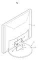
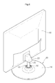
- FIGS. 1 through 5 illustrate a display device, particularly, a liquid crystal display (LCD) monitor having a supporting apparatus according to a first exemplary embodiment of the present invention.
- the display device includes a main body 10 provided with a display screen (not shown), on which an image is displayed, at the front thereof, and a supporting apparatus 20 supporting the main body 10.
- a display screen not shown
- a supporting apparatus 20 supporting the main body 10.
- the supporting apparatus 20 includes a flat base 21 put on a table such as a desk in order to support the main body 10, a supporting bracket 22 coupled to a rear surface of the main body 10, and a stand 23 coupled to the flat base 21 at a lower portion thereof and to the supporting bracket 22 at an upper portion thereof. Further, the supporting apparatus 20 includes a joint 30, which rotatably connects the upper portion of the stand 23 and the supporting bracket 22 on the rear surface of the main body 10 so as to rotate the main body 10 backwards and forwards to adjust the viewing angle of the display screen of the main body 10.
- the supporting bracket 22 on the rear surface of the main body 10 is separately formed, and then coupled to the rear surface of the main body 10 through a fastener such as a screw, or is integrally formed with the main body 10 in the process of forming a case of the main body 10.
- the stand 23 is fixed to the flat base 21 by screwing or adhering its lower end inserted into a fixing recess 24 of the flat base 21.
- the stand 23 may be pivotably coupled to the flat base 21 by, for instance, a hinge at the lower end thereof.
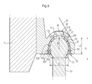
- the joint 30, which connects the upper portion of the stand 23 and the supporting bracket 22, includes a curved plug 31 that is provided at the upper portion of the stand 23, a curved socket 32 that is formed at the supporting bracket 22 so as to be coupled with the curved plug 31, an elastic member 33 that is interposed and connected between the curved plug 31 and the curved socket 32, and a reinforcement spring 50 that is covered on an outer surface of the elastic member 33 so as to reinforce elasticity of the elastic member 33.
- the curved plug 31 has the shape of a long cylinder, which is integrally formed with the stand 23.
- the curved plug 31 is oval in cross section such that the supporting bracket 22 can be coupled to be rotated backwards and forwards.
- the cross section of the curved plug 31 has a vertical diameter D1 larger than a horizontal diameter D2, as illustrated in FIG. 3.
- the cross section of the curved plug 31 may be circular, and preferably oval, in order to maintain stable connection with the supporting bracket 22 and uniform motion when the main body 10 is rotated. This construction will be described in detail below.
- the curved socket 32 of the supporting bracket 22 has the shape of a semi-circular dome, which is open downwards so as to allow the curved plug 31 and the elastic member 33 to be fitted thereinto.
- the elastic member 33 is semi-circular in cross section, and is formed of elastically deformable material such as rubber, silicon, or soft resin.
- the elastic member 33 has an inner contact surface 33a corresponding to an outer surface of the curved plug 31, and an outer contact surface 33b corresponding to an inner surface of the curved socket 32, and has the shape of a cap covered above the outer surface of the curved plug 31.
- the reinforcement spring 50 is formed by bending a predetermined width of steel sheet in a "C" shape, and is in close contact with the outer contact surface 33b of the elastic member 33.
- the reinforcement spring 50 presses the elastic member 33 in a radial inward direction, thereby reinforcing elastic force of the elastic member 33. This serves to allow friction to be maintained between the outer surface of the curved plug 31 and the outer contact surface 33b of the elastic member 33 by the elastic member 33, which is pressed in the radial inward direction by the reinforcement spring 50, although the elasticity of the elastic member 33 is varied due to long-term use.
- the outer contact surface 33b of the elastic member 33 is provided with a spring fitting recess 33c for fitting the reinforcement spring 50.
- the inner contact surface 33a of the elastic member 33 is brought in close contact with the outer surface of the curved plug 31, and the outer contact surface 33b of the elastic member 33 is brought in close contact with the inner surface of the curved socket 32 of the supporting bracket 22.
- the curved plug 31 is covered with the elastic member 33 and then the reinforcement spring 50 on the outer surface thereof, and then is fitted into the curved socket 32 of the supporting bracket 22.
- the elastic member 33 and the reinforcement spring 50 are deformed while fitted into the curved socket 32.
- the elastic and frictional forces of the elastic member 33 are applied to the outer surface of the curved plug 31 and the inner surface of the curved socket 32, so that the curved plug 31 is not easily separated from the curved socket 32.
- the inner contact surface 33a of the elastic member 33 has a horizontal width L1, of its opening, less than the horizontal diameter D2 of the curved plug 31, and has a vertical depth L2 greater than a vertical radius R of the curved plug 31. Hence, after the connection, the curved plug 31 of the stand 23 does not escape from the elastic member 33.
- the outer contact surface 33b of the elastic member 33 is provided with a corrugation having a convexity 35a and a concavity 35b, and the inner surface of the curved socket 32 is provided with a corrugation having a concavity corresponding to the convexity 35a and a convexity corresponding to the concavity 35b.
- the supporting apparatus of the present invention allows the supporting bracket 22 to be rotatably connected with the upper portion of the stand 23 only by pressure-fitting the curved plug 31 into the curved socket 32 of the supporting bracket 22 via the elastic member 33, so that it can be easier produced over the conventional one.
- the supporting apparatus of the present invention can connect the supporting bracket 22 with the stand 23 without a screw or a hinge shaft, so that it can make the production process simpler than the conventional one.
- the supporting apparatus of the present invention has a construction simpler than the conventional one, so that it can reduce production costs.
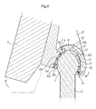
- the curved plug 31 and the supporting bracket 22 are mounted with a rotation stopper 40, which restricts a rotational range within which the main body 10 rotates backwards and forwards.
- the rotation stopper 40 includes at least one protrusion 41 that protrudes from the upper portion of the curved plug 31, and at least one slot 42 that is formed at the supporting bracket 22 in a rotating direction of the supporting bracket 22 so as to allow the protrusion 41 to be inserted thereinto.
- the elastic member 33 is also provided with at least one slot 43 through which the protrusion 41 passes.
- the protrusion 41 is provided with first and second catch steps 41a and 41b at opposite ends thereof, and the slot 42 is provided with first and second catch recesses 42a and 42b so as to catch the first and second catch steps 41a and 41b at opposite ends thereof.
- the first catch step 41a is caught in the first catch recess 42a when the main body 10 is rotated backwards.
- the second catch step 41b is caught in the second catch recess 42b when the main body 10 is rotated forwards.
- this construction is equally applied to the case where the main body 10 is rotated forwards.
- the force having a tendency to forward rotation is increased.
- the repulsive force P of the elastic member 33 acting on each of the rear upper and front lower portions of the curved plug 31 is increased, and acts as rotational resistance, so that the rotational force is uniformly maintained. Therefore, the motion of the main body 10 is uniformly maintained while the main body 10 is rotated.
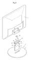
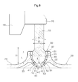
- FIGS. 6 through 11 illustrate a display device, particularly, a liquid crystal display (LCD) monitor having a supporting apparatus according to a second exemplary embodiment of the present invention.
- the display device includes a main body 100 provided with a display screen (not shown), on which an image is displayed, at the front thereof, and a supporting apparatus 200 supporting the main body 100.
- a display screen not shown
- the supporting apparatus 200 includes a flat base 210 put on a table such as a desk in order to support the main body 100, a supporting bracket 220 coupled to a rear surface of the main body 100, and a stand 230 coupled to the flat base 210 at a lower portion thereof and to the supporting bracket 220 at an upper portion thereof. Further, the supporting apparatus 200 includes a joint 300, which rotatably connects the lower portion of the stand 230 and the flat base 210 so as to rotate the main body 100 backwards and forwards to adjust a viewing angle of the display screen of the main body 100.
- FIG. 7 illustrates an example in which the upper portion of the stand 230 is fixed to the supporting bracket 220 of the rear surface of the main body 100.
- the present invention is not limited to this example.
- the stand 230 may be directly fixed to the main body 100 at the upper portion thereof, or be integrally formed with a case of the main body 100.
- the joint 300 which connects the lower portion of the stand 230 and the flat base 210, includes a curved plug 310 that is provided at the lower portion of the stand 230, a curved socket 320 that is formed at the flat base 210 so as to be coupled with the curved plug 310, and an elastic member 330 that is interposed and connected between the curved plug 310 and the curved socket 320.
- the curved plug 310 is integrally formed with the stand 230, and has the shape of a sphere so as to be rotatably coupled to the flat base 210.
- the curved plug 310 is oval in cross section, thus having a vertical diameter D1 larger than a horizontal diameter D2, as illustrated in FIG. 8.
- the cross section of the curved plug 310 may be circular, and preferably oval, in order to maintain stable connection with the flat base 210 and uniform motion when the main body 100 is rotated backwards and forwards. This construction will be described in detail below.
- the curved socket 320 of the flat base 210 has the shape of a semi-circular cup hemisphere, which is open upwards so as to allow the curved plug 310 and the elastic member 330 to be fitted thereinto.
- the elastic member 330 is semi-circular in cross section, and is formed of elastically deformable material such as rubber, silicon, or soft resin.
- the elastic member 330 has an inner contact surface 331 corresponding to an outer surface of the curved plug 310, and an outer contact surface 332 corresponding to an inner surface of the curved socket 320, and has the shape of a cap covered above the outer surface of the curved plug 310.
- the inner contact surface 331 of the elastic member 330 is brought in close contact with the outer surface of the curved plug 310, and the outer contact surface 332 of the elastic member 330 is brought in close contact with the inner surface of the curved socket 320 of the flat base 210.
- the curved plug 310 is covered with the elastic member 330 on the outer surface thereof, and then is fitted into the curved socket 320 of the flat base 210.
- the elastic member 330 is deformed while fitted into the curved socket 320.
- the elastic and frictional forces of the elastic member 330 are applied to the outer surface of the curved plug 310 and the inner surface of the curved socket 320, so that the curved plug 310 is not easily separated from the curved socket 320.
- the inner contact surface 331 of the elastic member 330 has a horizontal width D3, of its opening, less than the horizontal diameter D2 of the curved plug 310, and has a vertical depth L greater than a vertical radius R of the curved plug 310. Hence, after the connection, the curved plug 310 of the stand 230 does not escape from the elastic member 330.
- the outer contact surface 332 of the elastic member 330 is provided with a corrugation having a convexity 351 and a concavity 352, and the inner surface of the curved socket 320 is provided with a corrugation having a concavity corresponding to the convexity 351 and a convexity corresponding to the concavity 352.
- the supporting apparatus of the present invention allows the flat base 210 to be rotatably connected with the lower portion of the stand 230 only by pressure-fitting the curved plug 310 into the curved socket 320 of the flat base 210 via the elastic member 330, so that it can be easier produced over the conventional one.
- the supporting apparatus of the present invention can connect the flat base 210 with the stand 230 without a screw or a hinge shaft, so that it can make the production process simpler than the conventional one.
- the supporting apparatus of the present invention has a construction simpler than the conventional one, so that it can reduce production costs.
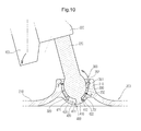
- the curved plug 310 and the supporting bracket 220 are mounted with a rotation stopper 400, which restricts a rotational range within which the main body 100 rotates backwards and forwards.
- the rotation stopper 400 includes a protrusion 410 that protrudes from the lower portion of the curved plug 310, and a slot 420 that is formed at the base 210 in a rotating direction of the curved plug 310 so as to allow the protrusion 410 to be inserted thereinto.
- the elastic member 330 is also provided with a slot 430 through which the protrusion 410 passes.
- the protrusion 410 is provided with first and second catch steps 411 and 412 at opposite ends thereof, and the slot 420 is provided with first and second catch recesses 421 and 422 so as to catch the first and second catch steps 411 and 412 at opposite ends thereof.
- the first catch step 411 is caught in the first catch recess 421 when the main body 100 is rotated backwards.
- the second catch step 412 is caught in the second catch recess 422 when the main body 100 is rotated forwards.
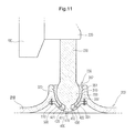
- FIG. 11 illustrates a modification of the joint 300.
- the lower portion of the curved socket 320 of the flat base 210 is provided with an opening, to which a lower cover 500 is coupled.
- the lower cover 500 is fixed to the lower portion of the flat base 210 by screws 510.
- the recess 420 of the rotation stopper 400 is allotted to the lower cover 500.
- the lower portion of the curved socket 320 is allowed to be opened or closed by the lower cover 500, so that the curved plug 310 of the stand 230 can be easier coupled to the curved socket 320 of the flat base 210.
- the rotational moment is in direct proportion to the rotational resistance.
- the rotational moment is applied in a direction opposite to the rotational resistance, so that the rotational force is constantly maintained.
- the motion of the main body 100 can be uniformly maintained regardless of the change in slope.
- this construction is equally applied to the case where the main body 100 is rotated forwards.
- the force having tendency to forward rotation is increased.
- the repulsive force P of the elastic member 330 acting on each of the rear upper and front lower portions of the curved plug 310 is increased, and acts as rotational resistance, so that the rotational force is uniformly maintained. Therefore, the motion of the main body 100 is uniformly maintained while the main body 100 is rotated.
- the supporting apparatus for display devices in accordance with the first exemplary embodiment of the present invention allows the supporting bracket to be rotatably connected with the stand only by pressure-fitting the curved plug into the curved socket of the supporting bracket via the elastic member, so that it can simplify the production process and thus be easier produced compared to the conventional one. Further, the supporting apparatus of the present invention has a construction simpler than the conventional one, so that it can reduce production costs.
- the rotational moment is applied in a direction opposite to the rotational resistance when rotating the main body backwards and forwards to adjust a viewing angle of the display screen of the main body, so that the rotational force is constantly maintained regardless of the change in the slope of the main body. Therefore, while the main body is rotated, the motion of the main body can be uniformly maintained.
- the reinforcement spring coupled on the outer surface of the elastic member presses the elastic member to be contracted, the friction between the outer surface of the curved plug and the inner contact surface of the elastic member can be maintained although the elastic member is varied in elasticity due to long-term use.
- the supporting apparatus for display devices in accordance with the second exemplary embodiment of the present invention allows the flat base to be rotatably connected with the stand only by pressure-fitting the curved plug of the stand into the curved socket of the flat base via the elastic member, so that it can simplify the production process and thus be produced easier than the conventional one.
- the rotational moment is applied in a direction opposite to the rotational resistance when rotating the main body backwards and forwards to adjust a viewing angle of the display screen of the main body, so that the rotational force is constantly maintained regardless of the change in the slope of the main body. Therefore, while the main body is rotated, the motion of the main body can be uniformly maintained.
- the rotation stopper because the rotational range of the main body is restricted by the rotation stopper, it is possible to prevent the main body from excessively rotating when adjusting the viewing angle of the display screen of the main body.
Landscapes
- Engineering & Computer Science (AREA)
- General Engineering & Computer Science (AREA)
- Mechanical Engineering (AREA)
- Devices For Indicating Variable Information By Combining Individual Elements (AREA)
Applications Claiming Priority (4)
| Application Number | Priority Date | Filing Date | Title |
|---|---|---|---|
| KR1020060075886A KR101312437B1 (ko) | 2006-08-10 | 2006-08-10 | 디스플레이장치용 지지장치 및 이를 갖춘 디스플레이장치 |
| KR1020060075884A KR101253570B1 (ko) | 2006-08-10 | 2006-08-10 | 디스플레이장치용 지지장치 및 이를 갖춘 디스플레이장치 |
| KR1020060075885A KR101202322B1 (ko) | 2006-08-10 | 2006-08-10 | 디스플레이장치용 지지장치 및 이를 갖춘 디스플레이장치 |
| KR1020060115311A KR101263435B1 (ko) | 2006-11-21 | 2006-11-21 | 디스플레이장치용 지지장치 및 이를 갖춘 디스플레이장치 |
Publications (2)
| Publication Number | Publication Date |
|---|---|
| EP1887273A2 true EP1887273A2 (fr) | 2008-02-13 |
| EP1887273A3 EP1887273A3 (fr) | 2009-06-10 |
Family
ID=38698850
Family Applications (1)
| Application Number | Title | Priority Date | Filing Date |
|---|---|---|---|
| EP07111119A Withdrawn EP1887273A3 (fr) | 2006-08-10 | 2007-06-27 | Appareil de support pour dispositifs de visualisation et dispositif de visualisation le comprenant |
Country Status (2)
| Country | Link |
|---|---|
| US (1) | US7694922B2 (fr) |
| EP (1) | EP1887273A3 (fr) |
Cited By (4)
| Publication number | Priority date | Publication date | Assignee | Title |
|---|---|---|---|---|
| CN103778863A (zh) * | 2014-01-26 | 2014-05-07 | 佛山市青松科技有限公司 | 一种led显示屏箱体支架 |
| WO2015055050A1 (fr) * | 2013-10-16 | 2015-04-23 | 无锡知谷网络科技有限公司 | Structure de support, joueur et dispositif mobile utilisant celui-ci |
| CN106287140A (zh) * | 2015-05-15 | 2017-01-04 | 富泰华工业(深圳)有限公司 | 支架 |
| CN113357496A (zh) * | 2021-06-08 | 2021-09-07 | 焦作师范高等专科学校 | 一种便于移动的心理学教学辅助教具 |
Families Citing this family (25)
| Publication number | Priority date | Publication date | Assignee | Title |
|---|---|---|---|---|
| KR20080105402A (ko) * | 2007-05-30 | 2008-12-04 | 삼성전자주식회사 | 지지장치 및 이를 갖는 디스플레이장치 |
| KR101390713B1 (ko) * | 2007-08-01 | 2014-04-30 | 삼성전자주식회사 | 디스플레이장치용 지지장치 및 이를 갖춘 디스플레이장치 |
| JP4530296B2 (ja) | 2008-04-09 | 2010-08-25 | Necアクセステクニカ株式会社 | 角度可変構造 |
| KR101470640B1 (ko) * | 2008-07-14 | 2014-12-08 | 엘지전자 주식회사 | 디스플레이 기기 |
| CN101770097B (zh) * | 2009-01-06 | 2012-11-21 | 群康科技(深圳)有限公司 | 显示装置 |
| JP4797111B1 (ja) * | 2010-05-27 | 2011-10-19 | 日立アロカメディカル株式会社 | 超音波診断装置 |
| USD628578S1 (en) * | 2010-06-03 | 2010-12-07 | Hannstar Display Corp. | Display stand |
| US20120175474A1 (en) * | 2011-01-06 | 2012-07-12 | Brandon Barnard | Electronic device holder |
| US8960632B2 (en) | 2011-07-05 | 2015-02-24 | Mediamounts, Ltd. | Dual bar linkage monitor support with adustment feature |
| WO2014052466A1 (fr) | 2012-09-25 | 2014-04-03 | Lilitab LLC | Joint à rotule pour boîtier de dispositif |
| US9163433B2 (en) | 2012-10-31 | 2015-10-20 | Invue Security Products Inc. | Display stand for a tablet computer |
| US9448588B2 (en) | 2012-12-12 | 2016-09-20 | Brandon Barnard | Electronic device holder |
| US9417678B2 (en) | 2013-03-15 | 2016-08-16 | Lilitab LLC | Magnet key |
| US9416915B2 (en) | 2013-03-15 | 2016-08-16 | Lilitab LLC | Configurable mounting system |
| US9797542B2 (en) | 2013-03-15 | 2017-10-24 | Lilitab LLC | Latch and bezel system for device enclosure |
| USD729222S1 (en) | 2013-03-15 | 2015-05-12 | Lilitab LLC | Magnetic mounting dock |
| US9195863B2 (en) | 2013-03-15 | 2015-11-24 | Lilitab LLC | Magnetic card reader mounting system |
| USD723546S1 (en) | 2013-03-15 | 2015-03-03 | Lilitab LLC | Tablet computer enclosure with card swipe |
| US9416912B2 (en) | 2013-03-15 | 2016-08-16 | Lilitab LLC | Wall mount with configurable stops |
| USD723545S1 (en) | 2013-03-15 | 2015-03-03 | Lilitab LLC | Tablet computer enclosure |
| US9599276B2 (en) | 2013-03-15 | 2017-03-21 | Lilitab LLC | Swivel mount |
| US9557767B2 (en) | 2013-03-15 | 2017-01-31 | Lilitab LLC | Interchangeable panels |
| WO2014151743A1 (fr) | 2013-03-15 | 2014-09-25 | Lilitab LLC | Appareil d'amarrage |
| US9845912B2 (en) | 2015-09-30 | 2017-12-19 | Invue Security Products Inc. | Gang charger, shroud, and dock for portable electronic devices |
| CN112382215B (zh) * | 2020-12-09 | 2022-11-22 | 深圳耐诺科技股份有限公司 | 一种可调节透明度的透明液晶显示屏幕 |
Citations (1)
| Publication number | Priority date | Publication date | Assignee | Title |
|---|---|---|---|---|
| KR20060074206A (ko) | 2004-12-27 | 2006-07-03 | 엘지전자 주식회사 | 모니터용 힌지어셈블리 |
Family Cites Families (13)
| Publication number | Priority date | Publication date | Assignee | Title |
|---|---|---|---|---|
| US3845928A (en) * | 1973-07-30 | 1974-11-05 | Lowrance Electronics Mfg | Spring loaded transducer bracket |
| US5108062A (en) * | 1990-09-28 | 1992-04-28 | Ncr Corporation | Pivot apparatus |
| US5652694A (en) * | 1996-02-01 | 1997-07-29 | Canon Business Machines, Inc. | Friction hinge including compressed friction washer |
| US5765794A (en) * | 1996-09-12 | 1998-06-16 | Chen; Ping | Angle adjusting device for an instrument panel |
| EP1113213A1 (fr) * | 1999-12-30 | 2001-07-04 | Rexnord Marbett S.p.A. | Pied d'appui pour corps lourds |
| KR100364732B1 (ko) * | 2000-07-08 | 2002-12-16 | 엘지전자 주식회사 | Lcd 모니터용 힌지 어셈블리 |
| US6553626B2 (en) * | 2001-08-27 | 2003-04-29 | Lee Valley Tools, Ltd. | Magnetic hinge |
| TW564984U (en) * | 2001-08-30 | 2003-12-01 | Hannstar Display Corp | Liquid crystal display with a ball-and-socket joint |
| AU2002222629A1 (en) * | 2001-12-13 | 2003-06-23 | Murakami Corporation | Direction regulator of display |
| KR100451803B1 (ko) * | 2001-12-27 | 2004-10-08 | 엘지전자 주식회사 | 평면 영상 표시 기기의 힌지 구조 |
| DE10213356C1 (de) * | 2002-03-26 | 2003-09-04 | Grundig Ag I Ins | Einrichtung zum Schwenken eines Gehäuses eines Geräts |
| TW570260U (en) * | 2003-05-16 | 2004-01-01 | Tatung Co | Tilt-angle rotating shaft structure of display |
| TWM254544U (en) * | 2003-10-29 | 2005-01-01 | Chin-Chih Lin | Pivot shaft structure for flat displaying device |
-
2007
- 2007-06-27 EP EP07111119A patent/EP1887273A3/fr not_active Withdrawn
- 2007-07-12 US US11/826,173 patent/US7694922B2/en not_active Expired - Fee Related
Patent Citations (1)
| Publication number | Priority date | Publication date | Assignee | Title |
|---|---|---|---|---|
| KR20060074206A (ko) | 2004-12-27 | 2006-07-03 | 엘지전자 주식회사 | 모니터용 힌지어셈블리 |
Cited By (4)
| Publication number | Priority date | Publication date | Assignee | Title |
|---|---|---|---|---|
| WO2015055050A1 (fr) * | 2013-10-16 | 2015-04-23 | 无锡知谷网络科技有限公司 | Structure de support, joueur et dispositif mobile utilisant celui-ci |
| CN103778863A (zh) * | 2014-01-26 | 2014-05-07 | 佛山市青松科技有限公司 | 一种led显示屏箱体支架 |
| CN106287140A (zh) * | 2015-05-15 | 2017-01-04 | 富泰华工业(深圳)有限公司 | 支架 |
| CN113357496A (zh) * | 2021-06-08 | 2021-09-07 | 焦作师范高等专科学校 | 一种便于移动的心理学教学辅助教具 |
Also Published As
| Publication number | Publication date |
|---|---|
| EP1887273A3 (fr) | 2009-06-10 |
| US20080035802A1 (en) | 2008-02-14 |
| US7694922B2 (en) | 2010-04-13 |
Similar Documents
| Publication | Publication Date | Title |
|---|---|---|
| US7694922B2 (en) | Supporting apparatus for display devices and display device having the same | |
| CN100381028C (zh) | 显示装置 | |
| KR101390713B1 (ko) | 디스플레이장치용 지지장치 및 이를 갖춘 디스플레이장치 | |
| US7198237B2 (en) | Stand assembly for monitor | |
| CN101034593B (zh) | 显示设备 | |
| US7578490B2 (en) | Stand of display device | |
| KR100512718B1 (ko) | 모니터장치 | |
| KR100500234B1 (ko) | 디스플레이장치 | |
| CN1933031B (zh) | 具有转动结构的显示装置 | |
| CN100392480C (zh) | 显示器 | |
| EP1959185A2 (fr) | Dispositif de support pour appareil d'affichage et appareil d'affichage le comprenant | |
| US20090101777A1 (en) | Wall mount supporting apparatus of flat panel display device | |
| WO2006112668A1 (fr) | Moniteur | |
| EP2557776B1 (fr) | Dispositif d'affichage | |
| US20060187625A1 (en) | Monitor apparatus | |
| US20060126282A1 (en) | Hinge assembly for a flat display monitor | |
| KR100765242B1 (ko) | 평판형 tv용 벽걸이식 거치대 | |
| US8593797B2 (en) | Display device | |
| KR101253570B1 (ko) | 디스플레이장치용 지지장치 및 이를 갖춘 디스플레이장치 | |
| KR101338886B1 (ko) | 각도 조절이 가능한 전자기기용 거치대 | |
| KR20080014336A (ko) | 디스플레이장치용 지지장치 및 이를 갖춘 디스플레이장치 | |
| KR101312437B1 (ko) | 디스플레이장치용 지지장치 및 이를 갖춘 디스플레이장치 | |
| KR101263435B1 (ko) | 디스플레이장치용 지지장치 및 이를 갖춘 디스플레이장치 | |
| TWI355229B (en) | Supporting mechanism and electric device using the | |
| CN102147998B (zh) | 显示装置 |
Legal Events
| Date | Code | Title | Description |
|---|---|---|---|
| PUAI | Public reference made under article 153(3) epc to a published international application that has entered the european phase |
Free format text: ORIGINAL CODE: 0009012 |
|
| AK | Designated contracting states |
Kind code of ref document: A2 Designated state(s): AT BE BG CH CY CZ DE DK EE ES FI FR GB GR HU IE IS IT LI LT LU LV MC MT NL PL PT RO SE SI SK TR |
|
| AX | Request for extension of the european patent |
Extension state: AL BA HR MK YU |
|
| PUAL | Search report despatched |
Free format text: ORIGINAL CODE: 0009013 |
|
| AK | Designated contracting states |
Kind code of ref document: A3 Designated state(s): AT BE BG CH CY CZ DE DK EE ES FI FR GB GR HU IE IS IT LI LT LU LV MC MT NL PL PT RO SE SI SK TR |
|
| AX | Request for extension of the european patent |
Extension state: AL BA HR MK RS |
|
| 17P | Request for examination filed |
Effective date: 20091209 |
|
| AKX | Designation fees paid |
Designated state(s): DE GB NL |
|
| 17Q | First examination report despatched |
Effective date: 20100203 |
|
| RAP1 | Party data changed (applicant data changed or rights of an application transferred) |
Owner name: SAMSUNG ELECTRONICS CO., LTD. |
|
| GRAP | Despatch of communication of intention to grant a patent |
Free format text: ORIGINAL CODE: EPIDOSNIGR1 |
|
| INTG | Intention to grant announced |
Effective date: 20180716 |
|
| STAA | Information on the status of an ep patent application or granted ep patent |
Free format text: STATUS: THE APPLICATION IS DEEMED TO BE WITHDRAWN |
|
| 18D | Application deemed to be withdrawn |
Effective date: 20181127 |