EP2557776B1 - Dispositif d'affichage - Google Patents
Dispositif d'affichage Download PDFInfo
- Publication number
- EP2557776B1 EP2557776B1 EP10849538.3A EP10849538A EP2557776B1 EP 2557776 B1 EP2557776 B1 EP 2557776B1 EP 10849538 A EP10849538 A EP 10849538A EP 2557776 B1 EP2557776 B1 EP 2557776B1
- Authority
- EP
- European Patent Office
- Prior art keywords
- hinge shaft
- elastic member
- hinge
- coupled
- flip
- Prior art date
- Legal status (The legal status is an assumption and is not a legal conclusion. Google has not performed a legal analysis and makes no representation as to the accuracy of the status listed.)
- Active
Links
Images


Classifications
-
- F—MECHANICAL ENGINEERING; LIGHTING; HEATING; WEAPONS; BLASTING
- F16—ENGINEERING ELEMENTS AND UNITS; GENERAL MEASURES FOR PRODUCING AND MAINTAINING EFFECTIVE FUNCTIONING OF MACHINES OR INSTALLATIONS; THERMAL INSULATION IN GENERAL
- F16M—FRAMES, CASINGS OR BEDS OF ENGINES, MACHINES OR APPARATUS, NOT SPECIFIC TO ENGINES, MACHINES OR APPARATUS PROVIDED FOR ELSEWHERE; STANDS; SUPPORTS
- F16M13/00—Other supports for positioning apparatus or articles; Means for steadying hand-held apparatus or articles
-
- F—MECHANICAL ENGINEERING; LIGHTING; HEATING; WEAPONS; BLASTING
- F16—ENGINEERING ELEMENTS AND UNITS; GENERAL MEASURES FOR PRODUCING AND MAINTAINING EFFECTIVE FUNCTIONING OF MACHINES OR INSTALLATIONS; THERMAL INSULATION IN GENERAL
- F16M—FRAMES, CASINGS OR BEDS OF ENGINES, MACHINES OR APPARATUS, NOT SPECIFIC TO ENGINES, MACHINES OR APPARATUS PROVIDED FOR ELSEWHERE; STANDS; SUPPORTS
- F16M11/00—Stands or trestles as supports for apparatus or articles placed thereon ; Stands for scientific apparatus such as gravitational force meters
- F16M11/02—Heads
- F16M11/04—Means for attachment of apparatus; Means allowing adjustment of the apparatus relatively to the stand
- F16M11/06—Means for attachment of apparatus; Means allowing adjustment of the apparatus relatively to the stand allowing pivoting
- F16M11/10—Means for attachment of apparatus; Means allowing adjustment of the apparatus relatively to the stand allowing pivoting around a horizontal axis
-
- G—PHYSICS
- G02—OPTICS
- G02F—OPTICAL DEVICES OR ARRANGEMENTS FOR THE CONTROL OF LIGHT BY MODIFICATION OF THE OPTICAL PROPERTIES OF THE MEDIA OF THE ELEMENTS INVOLVED THEREIN; NON-LINEAR OPTICS; FREQUENCY-CHANGING OF LIGHT; OPTICAL LOGIC ELEMENTS; OPTICAL ANALOGUE/DIGITAL CONVERTERS
- G02F1/00—Devices or arrangements for the control of the intensity, colour, phase, polarisation or direction of light arriving from an independent light source, e.g. switching, gating or modulating; Non-linear optics
- G02F1/01—Devices or arrangements for the control of the intensity, colour, phase, polarisation or direction of light arriving from an independent light source, e.g. switching, gating or modulating; Non-linear optics for the control of the intensity, phase, polarisation or colour
- G02F1/13—Devices or arrangements for the control of the intensity, colour, phase, polarisation or direction of light arriving from an independent light source, e.g. switching, gating or modulating; Non-linear optics for the control of the intensity, phase, polarisation or colour based on liquid crystals, e.g. single liquid crystal display cells
- G02F1/133—Constructional arrangements; Operation of liquid crystal cells; Circuit arrangements
- G02F1/1333—Constructional arrangements; Manufacturing methods
-
- F—MECHANICAL ENGINEERING; LIGHTING; HEATING; WEAPONS; BLASTING
- F16—ENGINEERING ELEMENTS AND UNITS; GENERAL MEASURES FOR PRODUCING AND MAINTAINING EFFECTIVE FUNCTIONING OF MACHINES OR INSTALLATIONS; THERMAL INSULATION IN GENERAL
- F16M—FRAMES, CASINGS OR BEDS OF ENGINES, MACHINES OR APPARATUS, NOT SPECIFIC TO ENGINES, MACHINES OR APPARATUS PROVIDED FOR ELSEWHERE; STANDS; SUPPORTS
- F16M2200/00—Details of stands or supports
- F16M2200/04—Balancing means
- F16M2200/041—Balancing means for balancing rotational movement of the head
-
- F—MECHANICAL ENGINEERING; LIGHTING; HEATING; WEAPONS; BLASTING
- F16—ENGINEERING ELEMENTS AND UNITS; GENERAL MEASURES FOR PRODUCING AND MAINTAINING EFFECTIVE FUNCTIONING OF MACHINES OR INSTALLATIONS; THERMAL INSULATION IN GENERAL
- F16M—FRAMES, CASINGS OR BEDS OF ENGINES, MACHINES OR APPARATUS, NOT SPECIFIC TO ENGINES, MACHINES OR APPARATUS PROVIDED FOR ELSEWHERE; STANDS; SUPPORTS
- F16M2200/00—Details of stands or supports
- F16M2200/08—Foot or support base
-
- Y—GENERAL TAGGING OF NEW TECHNOLOGICAL DEVELOPMENTS; GENERAL TAGGING OF CROSS-SECTIONAL TECHNOLOGIES SPANNING OVER SEVERAL SECTIONS OF THE IPC; TECHNICAL SUBJECTS COVERED BY FORMER USPC CROSS-REFERENCE ART COLLECTIONS [XRACs] AND DIGESTS
- Y10—TECHNICAL SUBJECTS COVERED BY FORMER USPC
- Y10S—TECHNICAL SUBJECTS COVERED BY FORMER USPC CROSS-REFERENCE ART COLLECTIONS [XRACs] AND DIGESTS
- Y10S248/00—Supports
- Y10S248/917—Video display screen support
- Y10S248/918—Ancillary device support associated with a video display screen
-
- Y—GENERAL TAGGING OF NEW TECHNOLOGICAL DEVELOPMENTS; GENERAL TAGGING OF CROSS-SECTIONAL TECHNOLOGIES SPANNING OVER SEVERAL SECTIONS OF THE IPC; TECHNICAL SUBJECTS COVERED BY FORMER USPC CROSS-REFERENCE ART COLLECTIONS [XRACs] AND DIGESTS
- Y10—TECHNICAL SUBJECTS COVERED BY FORMER USPC
- Y10S—TECHNICAL SUBJECTS COVERED BY FORMER USPC CROSS-REFERENCE ART COLLECTIONS [XRACs] AND DIGESTS
- Y10S248/00—Supports
- Y10S248/917—Video display screen support
- Y10S248/919—Adjustably orientable video screen support
- Y10S248/922—Angular
- Y10S248/923—Tilting
Definitions
- the present disclosure relates to a display device.
- Display devices display an image.
- Typical display devices used in desktop computers can be tilted at the level of a user's eyes.
- picture frame type display devices which employ a flip hinge stand, are drawing attention.
- Such flip hinge stands are manually tilted by a user, to adjust an image angle.
- Document US 6,899,311 B1 discloses a display arrangement including a flat panel display, a display housing, an adjustable leg for supporting the display housing and thus the flat panel display in an inclined position, and a hinge for coupling the adjustable leg to the display housing so that the adjustable leg is pivotable relative to the display housing.
- the hinge is configured to provide a tilting action for adjusting the tilt angle of the display arrangement, and a collapsing action for reducing the depth of the display arrangement.
- document US 2004/0055114 A1 discloses a hinge assembly for enabling a LCD display panel to be adjusted to a suitable viewing angle and the supporting stand to be folded up against the back of the display panel.
- Embodiments provide a display device that makes it possible to set an initial tilting angle of a flip hinge stand without adjusting a tilting angle.
- Embodiments also provide a display device that makes it possible for a user to adjust force needed for tilting a flip hinge stand.
- a display device includes the features of claim 1.
- a display apparatus may include: a display main body from which an image is output; and a flip hinge assembly coupled to the display main body, wherein the flip hinge assembly includes: a stationary part fixed to the display main body; a rotary part rotatably coupled to the stationary part; a first elastic member coupled to the rotary part and the stationary part; and a second elastic member, an end of which is coupled to the stationary part, and the other end thereof selectively contacts the rotary part, wherein the second elastic member applies elastic force to the rotary part in a direction opposite to a direction of elastic force the first elastic member applies to the rotary part.
- a display device in another embodiment, includes: a display main body from which an image is output; a hinge shaft coupled to a rear surface of the display main body; a flip hinge body coupled to the hinge shaft and rotating integrally with the hinge shaft; a first elastic member, an end of which is coupled to the display main body, and the other end thereof is coupled to the hinge shaft to pull the hinge shaft in a direction; a second elastic member having an end coupled to the display main body, wherein when an angle formed between the flip hinge body and the display main body is within a preset angle range, the other end of the second elastic member applies elastic force to the hinge shaft or the flip hinge body to rotate the hinge shaft in another direction.
- an initial tilting angle of a display main body is automatically set, thereby improving user convenience.
- force needed for tilting a display main body can be adjusted through simple manipulation.
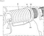
- Fig. 1 is a perspective view illustrating the rear part of a display device according to an embodiment.
- a display device 1 includes: a display main body 10 from which an image is output; and a flip hinge stand 20 coupled to a rear surface of the display main body 10 to support the display main body 10.
- the display main body 10 includes: a display module (not shown) on which an image is displayed; a front cabinet 12 constituting a front exterior of the display device 1; and a rear cabinet 11 constituting a rear exterior of the display device 1.
- Fig. 2 is a perspective view illustrating an inner part of a flip hinge stand according to the current embodiment.
- Fig. 3 is an exploded perspective view illustrating a flip hinge stand according to the current embodiment.
- Fig. 4 is an exploded perspective view illustrating a flip hinge assembly according to the current embodiment.
- Fig. 5 is a partial enlarged view illustrating a second coupling nut according to the current embodiment.
- the flip hinge stand 20 includes: a stand body 21 extending from the display main body 10; a flip hinge assembly 30 coupled to the stand body 21, and rotating the stand body 21 about the display main body 10; a plurality of hinge shaft housings 23 and 24 preventing the inner part of the flip hinge assembly 30 from being exposed; and a fastening member 25 for adjusting torque of the flip hinge assembly 30.
- the stand body 21 and a stand body 22 include a first body 21 and a second body 22, which are coupled to each other with a flip hinge body 33 (to be described later) therebetween.
- the first body 21 and the second body 22 may be coupled to each other by a hook.
- the stand bodies 21 and 22 have a space of a certain size therein to accommodate the flip hinge body 33.
- the stand bodies 21 and 22 are coupled to the flip hinge body 33 and rotate integrally with the flip hinge body 33.
- the stand bodies 21 and 22 may be coupled to the flip hinge body 33 by a coupling member.
- Holes 211 may pass through the first and second bodies 21 and 22.
- the hole 211 may decrease the weight of the stand body 21 and improve the appearance thereof.
- Recess parts 212 and 222 having a certain depth are disposed in the upper ends of the first and second bodies 21 and 22 to prevent the first and second bodies 21 and 22 from interfering with the hinge shaft housings 23 and 24 and a hinge shaft assembly to be described later.
- a fastening member insertion hole 214 is disposed in a side portion of the upper end of the first body 21 to receive the fastening member 25.
- the flip hinge assembly 30 includes: a hinge shaft 31 functioning as a rotation shaft when the display main body 10 is tilted; an auxiliary hinge shaft 32 coupled to the hinge shaft 31; the flip hinge body 33 rotating about the hinge shaft 31; a coupling bracket 34 supporting an end of the hinge shaft 31 and coupling to the display main body 10; a supporting bracket 35 coupled to the coupling bracket 34 to support the other end of the hinge shaft 31; and first and second elastic members 36 and 37 providing elastic force to the flip hinge body 33.
- the hinge shaft 31 and the auxiliary hinge shaft 32 are coupled to each other to constitute a hinge shaft assembly.
- the hinge shaft 31 and the auxiliary hinge shaft 32 as two parts constitute the hinge shaft assembly, the hinge shaft 31 and the auxiliary hinge shaft 32 can be more easily coupled to the flip hinge body 33 than an unified hinge shaft assembly is coupled thereto.
- the hinge shaft 31 includes: a body part 311; a first non-circular part 312 having a non-circular shape, and inserted in the flip hinge body 33; and a first male screw part 313 disposed at an end of the hinge shaft 31.
- the body part 311 When the hinge shaft 31 is coupled to the flip hinge body 33, the body part 311 is disposed in a left and right direction within the flip hinge body 33.
- the body part 311 may have a cylindrical shape.
- An elastic member fixing recess 311a may be disposed in the body part 311, and an end of the first elastic member 36 may be fixed to the elastic member fixing recess 311a. As the hinge shaft 31 rotates, the end of the first elastic member 36 inserted in the elastic member fixing recess 311a is also rotated.
- the body part 311 may have a hollow to accommodate a portion of the auxiliary hinge shaft 32.
- An insertion hole 314 is disposed in the body part 311 to accommodate a pressing member 315.
- the pressing member 315 contacts the second elastic member 37 to deform the second elastic member 37.
- the pressing member 315 is inserted in the insertion hole 314, and is protruded a predetermined length from an outer circumferential surface of the hinge shaft 31.
- the pressing member 315 may be a screw. An operation of the pressing member 315 for deforming the second elastic member 37 will be described later.
- the first non-circular part 312 is extended from the body part 311. When the flip hinge body 33 is rotated, the first non-circular part 312 substantially contacts the flip hinge body 33.
- the first non-circular part 312 has a non-circular shape such as a hexagonal shape, when the flip hinge body 33 is rotated, the first non-circular part 312 is rotated integrally with the hinge shaft 31.
- the first male screw part 313 is extended from the first non-circular part 312 and has a screw thread to be fastened by a first coupling nut 38.
- the auxiliary hinge shaft 32 includes: an insertion part 321 inserted in the body part 311; a second non-circular part 322 having a non-circular shape and inserted in the flip hinge body 33; and a second male screw part 323 extended from the insertion part 321.
- the insertion part 321 has a shape corresponding to an inner circumferential shape of the body part 311, so that the insertion part 321 can be inserted therein.
- the insertion part 321 may have a circular shape.
- the second non-circular part 22 substantially contacts the flip hinge body 33.
- the second non-circular part 322 has a non-circular shape such as a hexagonal shape, when the flip hinge body 33 is rotated, the second non-circular part 322 is rotated integrally with the auxiliary hinge shaft 32.
- the second male screw part 323 is extended from the second non-circular part 322 and has a screw thread to be fastened by a second coupling nut 39.
- the flip hinge body 33 includes: a body part 330 coupled to the stand body 21; a first insertion bracket 331 disposed on a side portion of the upper end of the body part 330; and a second insertion bracket 333 disposed on another side portion of the upper end of the body part 330.
- Through holes 330a may be disposed in the body part 330. Coupling members pass through the through holes 330a to couple the body part 330 to the first body 21.
- a recess part 336 may be recessed a predetermined depth in the upper end of the body part 330. When the flip hinge body 33 is rotated, the recess part 336 prevents the flip hinge body 33 from interfering with the hinge shaft housing 23.
- the first insertion bracket 331 has a first insertion hole 332 in which the hinge shaft 31 is inserted.
- the second insertion bracket 333 has a second insertion hole 334 in which the auxiliary hinge shaft 32 is inserted.
- the first insertion hole 332 has a non-circular shape corresponding to the first non-circular part 312.
- the second insertion hole 334 has a non-circular shape corresponding to the second non-circular part 322.
- the first coupling nut 38 is coupled to an end of the hinge shaft 31 to couple the hinge shaft 31 to the flip hinge body 33.
- a female screw is disposed in the first coupling nut 38 to be screwed to the first male screw part 313.
- the first coupling nut 38 prevents the hinge shaft 31 from being removed from the flip hinge body 33.
- the second coupling nut 39 is coupled to an end of the auxiliary hinge shaft 32 to couple the auxiliary hinge shaft 32 to the flip hinge body 33.
- a female screw is disposed in the second coupling nut 39 to be screwed to the second male screw part 323.
- a fastening male screw part 391 is disposed on an outer portion of the second coupling nut 39, and is screwed to the fastening member 25.
- the hinge shaft assembly is covered with the hinge shaft housings 23 and 24.
- the hinge shaft housing 23 includes a first hinge shaft housing 23 covering the lower part of the hinge shaft assembly, and a second hinge shaft housing 24 covering the upper part of the hinge shaft assembly.
- hinge shaft housings 23 and 24 include: coupling parts 231 and 241 for coupling to the display main body 10; and cover parts 232 and 242 extending rearward from the coupling parts 231 and 241, and covering the hinge shaft assembly.
- Coupling holes 231a and 241a through which coupling members pass are disposed in the coupling parts 231 and 241.
- the coupling members sequentially passed through the coupling holes 231a and 241a and the coupling bracket 34, are inserted in the display main body 10. That is, the hinge shaft housings 23 and 24 are coupled to the display main body 10 with the coupling bracket 34 therebetween.
- the flip hinge assembly 30 includes a plurality of washers W.
- the washers W have a circular disk shape with a hole through which the hinge shaft 31 or the auxiliary hinge shaft 32 passes.
- the washers W may include: a first washer W1 inserted between the flip hinge body 33 and the second coupling nut 39; a second washer W2 inserted between the flip hinge body 33 and the supporting bracket 35; a third washer W3 inserted between the first elastic member 36 and the supporting bracket 35; a fourth washer W4 inserted between the second elastic member 37 and a hinge shaft support part 341 to be described later; and a fifth washer W5 inserted between the flip hinge body 33 and the first coupling nut 38.
- the washers W are disposed between components of the flip hinge assembly 30 to facilitate rotation of the components and protect the components from damage.
- the fastening member 25 is coupled to the second coupling nut 39.
- the fastening member 25 includes a fastening part 251 for rotating the second coupling nut 39, and an extension part 252 extending from the fastening part 251.
- the fastening part 251 has an insertion hole 251a in which the second coupling nut 39 can be inserted.
- a female screw part (not shown) that can be screwed to the fastening male screw part 391 is disposed in an inner circumferential surface of the insertion hole 251a.
- a user applies force substantially to the extension part 252 to rotate the fastening part 251.
- the fastening member 25 may be rotated in a direction in which a user fastens the second coupling nut 39, that is, in a direction C of Fig. 5 , whereby the second coupling nut 39 presses the first washer W1. That is, the first washer W1 and the second washer W2 press the second insertion bracket 333 of the flip hinge body 33 from both sides thereof.
- the fastening member 25 may be rotated in a direction in which a user unfastens the second coupling nut 39, that is, in a direction D of Fig. 5 , whereby the second coupling nut 39 releases the first washer W1.
- the flip hinge body 33 can be rotated about the display main body 10 with small force. That is, it is easy to change an angle between the flip hinge body 33 and the display main body 10.
- the coupling bracket 34 is coupled to the rear surface of the display main body 10.
- the hinge shaft support part 341 for supporting a portion of the hinge shaft 31 may be formed by bending a portion of the coupling bracket 34.
- the hinge shaft support part 341 has a through hole 341a through which the hinge shaft 31 passes.
- the hinge shaft support part 341 may be provided with a second elastic member fixing part 341b (refer to Fig. 7 ) to which the second elastic member 37 to be described later is fixed.
- a connecting ring 40 may be inserted between the hinge shaft support part 341 and the first insertion bracket 331 of the flip hinge body 33. Washers W6 may be fitted on both side portions of the connecting ring 40 to facilitate rotation of the connecting ring 40.
- the supporting bracket 35 is coupled to the coupling bracket 34 to support a side portion of the hinge shaft 31.
- the supporting bracket 35 may be bent at a predetermined angle.
- the supporting bracket 35 has: a through hole 351 through which the hinge shaft 31 passes through; a plurality of coupling holes 352 through which coupling members for coupling the supporting bracket 35 and the coupling bracket 34 pass; an elastic member fixing recess 353 (refer to Fig. 6 ) in which an end of the first elastic member 36 is inserted.
- the supporting bracket 35 may be formed separately from the coupling bracket 34 according to the current embodiment, or be integrally formed therewith.
- the supporting bracket 35 may be formed by bending a portion of the coupling bracket 34, like the hinge shaft support part 341.
- the width of the flip hinge body 33 is allowed to be varied.
- Rotatable parts such as the hinge shaft 31, the auxiliary hinge shaft 32, the pressing member 315, and the flip hinge body 33, may be referred to as rotary parts, and parts fixed without rotation to the display main body 10, such as the coupling bracket 34 and the supporting bracket 35, may be referred to as stationary parts.
- Fig. 6 is a partial enlarged view illustrating a first elastic member installed according to the current embodiment.
- Fig. 7 is a partial enlarged view illustrating a second elastic member installed according to the current embodiment.
- the first elastic member 36 is coupled to the supporting bracket 35 and the hinge shaft 31. Particularly, an end of the first elastic member 36 is fixed to the elastic member fixing recess 353 of the supporting bracket 35, and the other end thereof is fixed to the elastic member fixing recess 311a of the hinge shaft 31.
- the first elastic member 36 may be a torsion spring.
- the hinge shaft 31 When the flip hinge body 33 rotates, the hinge shaft 31 also rotates. Thus, an end of the first elastic member 36 is fixed to the supporting bracket 35, and the other end thereof is rotated together with the hinge shaft 31. Accordingly, the first elastic member 36 is twisted to thereby apply elastic force to the hinge shaft 31.
- the first elastic member 36 returns the flip hinge body 33 to the original position thereof after the rotation.
- the second elastic member 37 may selectively contact the pressing member 315, an end of which is fixed to the coupling bracket 34, and the other end thereof is fixed to the hinge shaft 31.
- the second elastic member 37 may be a torsion spring, like the first elastic member 36.
- an end of the second elastic member 37 is fixed by the second elastic member fixing part 341b of the hinge shaft support part 341.
- the second elastic member fixing part 341b is formed by bending a portion of the hinge shaft support part 341.
- the end of the second elastic member 37 may be fitted and fixed between the second elastic member fixing part 341b and the hinge shaft 31.
- the other end of the second elastic member 37 may be bent at a predetermined angle.
- a line extended from the second end of the second elastic member 37 may be perpendicular to a line extended from the first end of the second elastic member 37.
- the second end of the second elastic member 37, bent at a predetermined angle, selectively catches the pressing member 315, and thus, may be referred to as a catching part 371.
- the flip hinge body 33 When the flip hinge body 33 is rotated through a predetermined angle or greater by the first elastic member 36, the second end of the second elastic member 37 contacts the pressing member 315. Then, the second end of the second elastic member 37, that is, the catching part 371 catches the pressing member 315, to thereby prevent further rotation of the flip hinge body 33.
- the second elastic member 37 applies elastic force to the pressing member 315 in a direction (a direction B of Fig. 7 ) opposite to a direction (a direction A of Fig. 7 ) of elastic force of the first elastic member 36, so as to stop rotation of the flip hinge body 33 at a point where the elastic force of the first elastic member 36 and the elastic force of the second elastic member 37 are in equilibrium.
- Winding numbers, thicknesses, and materials of the first and second elastic members 36 and 37 may be adjusted such that when a front surface of the display main body 10 forms about 10 degrees with an imaginary vertical line, elastic force of the first elastic member 36 and the elastic force of the second elastic member 37 are in equilibrium.
- the winding number of the second elastic member 37 may be smaller than the winding number of the first elastic member 36.
- force the second elastic member 37 applies to the pressing member 315 is greater than force by which the first elastic member 36 rotates the flip hinge body 33, thereby preventing the first elastic member 36 from further rotating the flip hinge body 33.
- Fig. 8 is a side view illustrating a display device placed on a supporting surface, to which no external force is applied, according to the current embodiment.
- Fig. 9 is a side view illustrating a display device maximally inclined rearward according to the current embodiment.
- the flip hinge stand 20 when the display device 1 is stored in a box, the flip hinge stand 20 tightly contacts the display main body 10. To this end, certain force is applied to the flip hinge stand 20. Thus, the number of display devices 1 stored in a limited space such as a box can be maximized.
- the pressing member 315 deforms the second elastic member 37.
- the second elastic member 37 is restored to the original shape thereof, and the catching part 371 applies force to the pressing member 315 to thereby rotate the hinge shaft 31. Accordingly, the flip hinge body 33 is rotated together with the hinge shaft 31 clockwise on the basis of Fig. 8 .
- the first and second elastic members 36 and 37 apply force to the hinge shaft 31 in opposite directions.
- the rotation of the flip hinge body 33 is stopped at a point when elastic force of the first elastic member 36 and elastic force of the second elastic member 37 are in equilibrium.
- the second elastic member 37 contacts the pressing member 315.
- the second elastic member 37 is restored to the original shape thereof, so as to space the catching part 371 away from the pressing member 315.
- the display main body 10 When the display main body 10 is supported by a supporting surface and the flip hinge stand 20, external force may be applied to the display main body 10 to be tilted rearward. At this point, the flip hinge stand 20 is rotated, and the display main body 10 is inclined rearward. For example, the display main body 10 may be tilted rearward until the front surface of the display main body 10 forms about 68 degrees with the imaginary vertical line (Y).
- Y imaginary vertical line
- the first elastic member 36 is deformed to apply elastic force to the hinge shaft 31 in a direction to rotate the flip hinge stand 20 to the original position thereof.
- the flip hinge stand 20 is returned to the original position thereof.
- the angle between the display main body 10 and the imaginary vertical line Y may be maintained to be greater than about 10 degrees.
- the display main body 10 may be tilted to a desired angle, and the second coupling nut 39 may be tightly fastened using the fastening member 25, thereby fixing inclination angles of the flip hinge body 33 and the stand body 30.
- the display main body 10 may be easily tilted using small external force.
- the second coupling nut 39 may be unfastened using the fastening member 25, thereby decreasing frictional force applied to the flip hinge body 33.
- initial tilting of the display main body 10 is automatically set.
- a user can adjust frictional force applied to the flip hinge body 33, by using the fastening member 25, thus adjusting force needed for tilting the display main body 10.
- the hinge shaft 31 is supported by the coupling bracket 34 and the supporting bracket 35 in the current embodiment, the hinge shaft 31 may be installed on the display main body 10.
- the ends of the first elastic member 36 and the second elastic member 37 are fixed to the coupling bracket 34 and the supporting bracket 35.
Landscapes
- Engineering & Computer Science (AREA)
- General Engineering & Computer Science (AREA)
- Mechanical Engineering (AREA)
- Physics & Mathematics (AREA)
- Nonlinear Science (AREA)
- Mathematical Physics (AREA)
- Chemical & Material Sciences (AREA)
- Crystallography & Structural Chemistry (AREA)
- General Physics & Mathematics (AREA)
- Optics & Photonics (AREA)
- Devices For Indicating Variable Information By Combining Individual Elements (AREA)
- Pivots And Pivotal Connections (AREA)
Claims (8)
- Dispositif d'affichage comprenant :un corps principal affichage (10) à partir duquel une image est émise ; etun ensemble charnière rabattable (30) couplé au corps principal d'affichage (10),l'ensemble charnière rabattable (30) comprenant :une partie fixe fixée au corps principal d'affichage (10) ;une partie rotative couplée de manière rotative à la partie fixe ;un premier élément élastique (36) couplé à la partie rotative et à la partie fixe ; etun second élément élastique (37), dont une extrémité est couplée à la partie fixe et dont l'autre extrémité entre de manière sélective en contact avec la partie rotative,le second élément élastique (37) appliquant une force élastique à la partie rotative dans une direction opposée à une direction d'une force élastique que le premier élément élastique (36) applique à la partie rotative,caractérisé par le fait que la partie rotative comprend :un ensemble tige de charnière comprenant une tige de charnière (31) et une tige de charnière auxiliaire (32) couplée à la tige de charnière (31), la tige de charnière (31) servant de tige de rotation lorsque le corps principal d'affichage (10) est incliné ; etun corps de charnière rabattable (33) tournant autour de la tige de charnière (31),la tige de charnière (31) et la tige de charnière auxiliaire (32) étant couplées au corps de charnière rabattable (33),la partie fixe comprenant :une ferrure de couplage (34) couplée à une surface arrière du corps principal d'affichage (10), et supportant une partie latérale de la tige de charnière (31) ; etune ferrure de support (35) couplée à la ferrure de couplage (34), et supportant une autre partie latérale de la tige de charnière (31),une extrémité du premier élément élastique (36) étant couplée à la ferrure de support (35), et l'autre extrémité de celui-ci étant couplée à la tige de charnière (31).
- Dispositif d'affichage selon la revendication 1, dans lequel la tige de charnière (31) comprend une partie non-circulaire (312, 322) ayant une section transversale non-circulaire,
le corps de charnière rabattable (33) a un trou d'introduction (332, 334) dans lequel la tige de charnière (31) est introduite, et
le trou d'introduction (332, 334) a une forme correspondant à la partie non-circulaire. - Dispositif d'affichage selon la revendication 1, comprenant en outre un élément de pression (315) qui est couplé à la tige de charnière (31) et entre de manière sélective en contact avec le second élément élastique (37).
- Dispositif d'affichage selon la revendication 3, dans lequel le second élément élastique (37) est courbé de telle sorte que la première extrémité de celui-ci est couplée à la ferrure de couplage (34) et la seconde extrémité de celui-ci entre de manière sélective en contact avec l'élément de pression (315).
- Dispositif d'affichage selon la revendication 1, dans lequel, lorsqu'un angle formé entre le corps de charnière rabattable (33) et le corps principal d'affichage (10) se situe dans une plage d'angle prédéfinie, le second élément élastique (37) entre en contact avec la partie rotative.
- Dispositif d'affichage selon la revendication 1, dans lequel un écrou de couplage pour coupler le corps de charnière rabattable (33) à la tige de charnière (31) est couplé à une extrémité de la tige de charnière (31), et
un élément de fixation (25) est couplé à l'écrou de couplage pour fixer l'écrou de couplage. - Dispositif d'affichage selon la revendication 6, dans lequel une partie de vis mâle de fixation est disposée sur une partie externe de l'écrou de couplage, et
une partie de vis femelle qui est vissée à la partie de vis mâle de fixation est disposée sur une partie interne de l'élément de fixation. - Dispositif d'affichage selon la revendication 1, dans lequel le premier élément élastique (36) et le second élément élastique (37) sont des ressorts de torsion.
Applications Claiming Priority (2)
| Application Number | Priority Date | Filing Date | Title |
|---|---|---|---|
| KR1020100030870A KR101736499B1 (ko) | 2010-04-05 | 2010-04-05 | 디스플레이 기기 |
| PCT/KR2010/007449 WO2011126191A1 (fr) | 2010-04-05 | 2010-10-28 | Dispositif d'affichage |
Publications (3)
| Publication Number | Publication Date |
|---|---|
| EP2557776A1 EP2557776A1 (fr) | 2013-02-13 |
| EP2557776A4 EP2557776A4 (fr) | 2016-05-25 |
| EP2557776B1 true EP2557776B1 (fr) | 2017-12-06 |
Family
ID=44763109
Family Applications (1)
| Application Number | Title | Priority Date | Filing Date |
|---|---|---|---|
| EP10849538.3A Active EP2557776B1 (fr) | 2010-04-05 | 2010-10-28 | Dispositif d'affichage |
Country Status (5)
| Country | Link |
|---|---|
| US (1) | US8837130B2 (fr) |
| EP (1) | EP2557776B1 (fr) |
| KR (1) | KR101736499B1 (fr) |
| CN (1) | CN102859999B (fr) |
| WO (1) | WO2011126191A1 (fr) |
Families Citing this family (7)
| Publication number | Priority date | Publication date | Assignee | Title |
|---|---|---|---|---|
| USD769865S1 (en) * | 2013-12-27 | 2016-10-25 | Intel Corporation | Portable all-in-one personal computer |
| CN105650105B (zh) * | 2014-11-11 | 2018-09-25 | 宏碁股份有限公司 | 转轴结构 |
| TWM511736U (zh) * | 2015-07-21 | 2015-11-01 | Syncmold Entpr Corp | 自開式支撐裝置 |
| WO2017131646A1 (fr) * | 2016-01-27 | 2017-08-03 | Hewlett-Packard Development Company, L.P. | Supports de dispositifs présentant des parois latérales de différentes inclinaisons |
| USD1074652S1 (en) * | 2022-07-20 | 2025-05-13 | Lg Electronics Inc. | Stand for television receiver |
| JP1773887S (ja) * | 2022-07-20 | 2024-06-25 | スタンド付きテレビジョン受像機 | |
| US12078286B1 (en) * | 2024-01-21 | 2024-09-03 | Pioneer Square Brands, Inc. | Stand for portable electronic device |
Family Cites Families (21)
| Publication number | Priority date | Publication date | Assignee | Title |
|---|---|---|---|---|
| CN2273435Y (zh) * | 1996-10-25 | 1998-01-28 | 新日兴弹簧机械工业股份有限公司 | 枢纽器 |
| KR100390410B1 (ko) * | 2000-06-20 | 2003-07-07 | 엘지전자 주식회사 | 힌지 조립체 |
| KR100364732B1 (ko) * | 2000-07-08 | 2002-12-16 | 엘지전자 주식회사 | Lcd 모니터용 힌지 어셈블리 |
| KR100463524B1 (ko) * | 2002-05-29 | 2004-12-29 | 엘지전자 주식회사 | 영상표시기기용 힌지어셈블리 |
| US20040055114A1 (en) * | 2002-09-19 | 2004-03-25 | Lu Sheng-Nan | Hinge assembly for supporting LCD display panel |
| US6899311B1 (en) * | 2003-01-22 | 2005-05-31 | Apple Computer, Inc. | Easel display arrangement |
| US6769657B1 (en) * | 2003-04-09 | 2004-08-03 | Min Hwa Huang | Support device for monitor, display or objects |
| KR20050083378A (ko) * | 2004-02-23 | 2005-08-26 | 엘지전자 주식회사 | 액정 표시 모니터의 힌지 조립체 구조 |
| KR100658836B1 (ko) * | 2005-08-16 | 2006-12-15 | 엘지전자 주식회사 | 스탠드 장치 |
| US7421762B2 (en) * | 2006-01-18 | 2008-09-09 | Shin Zu Shing Co., Ltd. | Hinge for a liquid crystal display |
| KR100769518B1 (ko) * | 2006-01-26 | 2007-10-31 | 피케이텍시스템 주식회사 | 플랜지형 디스크스프링이 구비된 힌지장치 |
| KR101237560B1 (ko) * | 2006-02-17 | 2013-02-26 | 엘지전자 주식회사 | 디스플레이 기기의 스탠드 |
| JP2007281345A (ja) * | 2006-04-11 | 2007-10-25 | Sony Corp | スタンドの回動機構及び電子機器 |
| TW200739176A (en) * | 2006-04-11 | 2007-10-16 | Fulfil Tech Co Ltd | Supporting apparatus with going up-and-down |
| KR100841319B1 (ko) * | 2006-08-16 | 2008-06-26 | 엘지전자 주식회사 | 영상표시장치 |
| KR100826198B1 (ko) * | 2006-08-16 | 2008-04-30 | 엘지전자 주식회사 | 영상표시장치 |
| JP2008104706A (ja) * | 2006-10-26 | 2008-05-08 | Ladonna:Kk | 展示器具 |
| US7934292B2 (en) * | 2007-01-04 | 2011-05-03 | Apple Inc. | Hinge mechanism |
| TWM331275U (en) * | 2007-08-01 | 2008-04-21 | Jarllytec Co Ltd | Stopping device of rotating shaft structure |
| CN101684882B (zh) * | 2008-09-25 | 2012-07-18 | 鸿富锦精密工业(深圳)有限公司 | 升降机构 |
| US8226054B2 (en) * | 2010-10-18 | 2012-07-24 | Syncmold Enterprise Corp. | Display frame and support unit thereof |
-
2010
- 2010-04-05 KR KR1020100030870A patent/KR101736499B1/ko active Active
- 2010-10-28 US US13/639,462 patent/US8837130B2/en active Active
- 2010-10-28 CN CN201080066024.7A patent/CN102859999B/zh active Active
- 2010-10-28 WO PCT/KR2010/007449 patent/WO2011126191A1/fr not_active Ceased
- 2010-10-28 EP EP10849538.3A patent/EP2557776B1/fr active Active
Non-Patent Citations (1)
| Title |
|---|
| None * |
Also Published As
| Publication number | Publication date |
|---|---|
| KR20110111673A (ko) | 2011-10-12 |
| KR101736499B1 (ko) | 2017-05-16 |
| EP2557776A1 (fr) | 2013-02-13 |
| CN102859999B (zh) | 2015-10-14 |
| WO2011126191A1 (fr) | 2011-10-13 |
| CN102859999A (zh) | 2013-01-02 |
| US8837130B2 (en) | 2014-09-16 |
| US20130027859A1 (en) | 2013-01-31 |
| EP2557776A4 (fr) | 2016-05-25 |
Similar Documents
| Publication | Publication Date | Title |
|---|---|---|
| EP2557776B1 (fr) | Dispositif d'affichage | |
| KR100463524B1 (ko) | 영상표시기기용 힌지어셈블리 | |
| US8348206B2 (en) | Electronic device | |
| KR101390713B1 (ko) | 디스플레이장치용 지지장치 및 이를 갖춘 디스플레이장치 | |
| US8047488B2 (en) | Support stand and flat-panel display monitor using the same | |
| EP1887273A2 (fr) | Appareil de support pour dispositifs de visualisation et dispositif de visualisation le comprenant | |
| CN201944511U (zh) | 铰接底座和枢接的铰接底座 | |
| US7798460B2 (en) | Apparatus to support a display device | |
| KR100568181B1 (ko) | 디스플레이 장치 | |
| US20080078061A1 (en) | Hinge assembly for foldable electronic device | |
| US20070029457A1 (en) | Stand of display device | |
| US20060265839A1 (en) | Axle positioning structure | |
| US7447007B2 (en) | Portable computer | |
| JP2014035507A (ja) | 表示装置 | |
| KR100802384B1 (ko) | 디스플레이 회동 장치 및 이것과 디스플레이의 결합 방법 | |
| JP3135891B2 (ja) | 液晶ディスプレイのアームスタンド | |
| US6859356B2 (en) | Apparatus for supporting a monitor | |
| JP4597875B2 (ja) | 資料提示装置用の撮像カメラヘッド | |
| CN103871322B (zh) | 显示器 | |
| JP2005208080A (ja) | ディスプレイ支持装置 | |
| KR200231314Y1 (ko) | 모니터 | |
| TWI355229B (en) | Supporting mechanism and electric device using the | |
| JP2005128471A (ja) | 液晶テレビジョン受像機 | |
| KR200329865Y1 (ko) | 모니터장치 | |
| KR20120017964A (ko) | 디스플레이 기기의 스탠드 장치 |
Legal Events
| Date | Code | Title | Description |
|---|---|---|---|
| PUAI | Public reference made under article 153(3) epc to a published international application that has entered the european phase |
Free format text: ORIGINAL CODE: 0009012 |
|
| 17P | Request for examination filed |
Effective date: 20120926 |
|
| AK | Designated contracting states |
Kind code of ref document: A1 Designated state(s): AL AT BE BG CH CY CZ DE DK EE ES FI FR GB GR HR HU IE IS IT LI LT LU LV MC MK MT NL NO PL PT RO RS SE SI SK SM TR |
|
| DAX | Request for extension of the european patent (deleted) | ||
| RA4 | Supplementary search report drawn up and despatched (corrected) |
Effective date: 20160425 |
|
| RIC1 | Information provided on ipc code assigned before grant |
Ipc: H04N 5/655 20060101AFI20160419BHEP |
|
| STAA | Information on the status of an ep patent application or granted ep patent |
Free format text: STATUS: EXAMINATION IS IN PROGRESS |
|
| 17Q | First examination report despatched |
Effective date: 20161110 |
|
| RIN1 | Information on inventor provided before grant (corrected) |
Inventor name: BAE, DUCKHO Inventor name: HYUN, JAE MIN |
|
| GRAP | Despatch of communication of intention to grant a patent |
Free format text: ORIGINAL CODE: EPIDOSNIGR1 |
|
| STAA | Information on the status of an ep patent application or granted ep patent |
Free format text: STATUS: GRANT OF PATENT IS INTENDED |
|
| INTG | Intention to grant announced |
Effective date: 20170530 |
|
| GRAS | Grant fee paid |
Free format text: ORIGINAL CODE: EPIDOSNIGR3 |
|
| GRAA | (expected) grant |
Free format text: ORIGINAL CODE: 0009210 |
|
| STAA | Information on the status of an ep patent application or granted ep patent |
Free format text: STATUS: THE PATENT HAS BEEN GRANTED |
|
| AK | Designated contracting states |
Kind code of ref document: B1 Designated state(s): AL AT BE BG CH CY CZ DE DK EE ES FI FR GB GR HR HU IE IS IT LI LT LU LV MC MK MT NL NO PL PT RO RS SE SI SK SM TR |
|
| REG | Reference to a national code |
Ref country code: GB Ref legal event code: FG4D |
|
| REG | Reference to a national code |
Ref country code: AT Ref legal event code: REF Ref document number: 953367 Country of ref document: AT Kind code of ref document: T Effective date: 20171215 Ref country code: CH Ref legal event code: EP |
|
| REG | Reference to a national code |
Ref country code: IE Ref legal event code: FG4D |
|
| REG | Reference to a national code |
Ref country code: DE Ref legal event code: R096 Ref document number: 602010047263 Country of ref document: DE |
|
| REG | Reference to a national code |
Ref country code: NL Ref legal event code: MP Effective date: 20171206 |
|
| REG | Reference to a national code |
Ref country code: LT Ref legal event code: MG4D |
|
| PG25 | Lapsed in a contracting state [announced via postgrant information from national office to epo] |
Ref country code: FI Free format text: LAPSE BECAUSE OF FAILURE TO SUBMIT A TRANSLATION OF THE DESCRIPTION OR TO PAY THE FEE WITHIN THE PRESCRIBED TIME-LIMIT Effective date: 20171206 Ref country code: SE Free format text: LAPSE BECAUSE OF FAILURE TO SUBMIT A TRANSLATION OF THE DESCRIPTION OR TO PAY THE FEE WITHIN THE PRESCRIBED TIME-LIMIT Effective date: 20171206 Ref country code: LT Free format text: LAPSE BECAUSE OF FAILURE TO SUBMIT A TRANSLATION OF THE DESCRIPTION OR TO PAY THE FEE WITHIN THE PRESCRIBED TIME-LIMIT Effective date: 20171206 Ref country code: NO Free format text: LAPSE BECAUSE OF FAILURE TO SUBMIT A TRANSLATION OF THE DESCRIPTION OR TO PAY THE FEE WITHIN THE PRESCRIBED TIME-LIMIT Effective date: 20180306 Ref country code: ES Free format text: LAPSE BECAUSE OF FAILURE TO SUBMIT A TRANSLATION OF THE DESCRIPTION OR TO PAY THE FEE WITHIN THE PRESCRIBED TIME-LIMIT Effective date: 20171206 |
|
| REG | Reference to a national code |
Ref country code: AT Ref legal event code: MK05 Ref document number: 953367 Country of ref document: AT Kind code of ref document: T Effective date: 20171206 |
|
| PG25 | Lapsed in a contracting state [announced via postgrant information from national office to epo] |
Ref country code: HR Free format text: LAPSE BECAUSE OF FAILURE TO SUBMIT A TRANSLATION OF THE DESCRIPTION OR TO PAY THE FEE WITHIN THE PRESCRIBED TIME-LIMIT Effective date: 20171206 Ref country code: BG Free format text: LAPSE BECAUSE OF FAILURE TO SUBMIT A TRANSLATION OF THE DESCRIPTION OR TO PAY THE FEE WITHIN THE PRESCRIBED TIME-LIMIT Effective date: 20180306 Ref country code: LV Free format text: LAPSE BECAUSE OF FAILURE TO SUBMIT A TRANSLATION OF THE DESCRIPTION OR TO PAY THE FEE WITHIN THE PRESCRIBED TIME-LIMIT Effective date: 20171206 Ref country code: RS Free format text: LAPSE BECAUSE OF FAILURE TO SUBMIT A TRANSLATION OF THE DESCRIPTION OR TO PAY THE FEE WITHIN THE PRESCRIBED TIME-LIMIT Effective date: 20171206 Ref country code: GR Free format text: LAPSE BECAUSE OF FAILURE TO SUBMIT A TRANSLATION OF THE DESCRIPTION OR TO PAY THE FEE WITHIN THE PRESCRIBED TIME-LIMIT Effective date: 20180307 |
|
| PG25 | Lapsed in a contracting state [announced via postgrant information from national office to epo] |
Ref country code: NL Free format text: LAPSE BECAUSE OF FAILURE TO SUBMIT A TRANSLATION OF THE DESCRIPTION OR TO PAY THE FEE WITHIN THE PRESCRIBED TIME-LIMIT Effective date: 20171206 |
|
| PG25 | Lapsed in a contracting state [announced via postgrant information from national office to epo] |
Ref country code: EE Free format text: LAPSE BECAUSE OF FAILURE TO SUBMIT A TRANSLATION OF THE DESCRIPTION OR TO PAY THE FEE WITHIN THE PRESCRIBED TIME-LIMIT Effective date: 20171206 Ref country code: SK Free format text: LAPSE BECAUSE OF FAILURE TO SUBMIT A TRANSLATION OF THE DESCRIPTION OR TO PAY THE FEE WITHIN THE PRESCRIBED TIME-LIMIT Effective date: 20171206 Ref country code: CZ Free format text: LAPSE BECAUSE OF FAILURE TO SUBMIT A TRANSLATION OF THE DESCRIPTION OR TO PAY THE FEE WITHIN THE PRESCRIBED TIME-LIMIT Effective date: 20171206 |
|
| PG25 | Lapsed in a contracting state [announced via postgrant information from national office to epo] |
Ref country code: AT Free format text: LAPSE BECAUSE OF FAILURE TO SUBMIT A TRANSLATION OF THE DESCRIPTION OR TO PAY THE FEE WITHIN THE PRESCRIBED TIME-LIMIT Effective date: 20171206 Ref country code: SM Free format text: LAPSE BECAUSE OF FAILURE TO SUBMIT A TRANSLATION OF THE DESCRIPTION OR TO PAY THE FEE WITHIN THE PRESCRIBED TIME-LIMIT Effective date: 20171206 Ref country code: PL Free format text: LAPSE BECAUSE OF FAILURE TO SUBMIT A TRANSLATION OF THE DESCRIPTION OR TO PAY THE FEE WITHIN THE PRESCRIBED TIME-LIMIT Effective date: 20171206 Ref country code: IT Free format text: LAPSE BECAUSE OF FAILURE TO SUBMIT A TRANSLATION OF THE DESCRIPTION OR TO PAY THE FEE WITHIN THE PRESCRIBED TIME-LIMIT Effective date: 20171206 Ref country code: RO Free format text: LAPSE BECAUSE OF FAILURE TO SUBMIT A TRANSLATION OF THE DESCRIPTION OR TO PAY THE FEE WITHIN THE PRESCRIBED TIME-LIMIT Effective date: 20171206 |
|
| REG | Reference to a national code |
Ref country code: DE Ref legal event code: R097 Ref document number: 602010047263 Country of ref document: DE |
|
| REG | Reference to a national code |
Ref country code: FR Ref legal event code: PLFP Year of fee payment: 9 |
|
| PLBE | No opposition filed within time limit |
Free format text: ORIGINAL CODE: 0009261 |
|
| STAA | Information on the status of an ep patent application or granted ep patent |
Free format text: STATUS: NO OPPOSITION FILED WITHIN TIME LIMIT |
|
| 26N | No opposition filed |
Effective date: 20180907 |
|
| PG25 | Lapsed in a contracting state [announced via postgrant information from national office to epo] |
Ref country code: SI Free format text: LAPSE BECAUSE OF FAILURE TO SUBMIT A TRANSLATION OF THE DESCRIPTION OR TO PAY THE FEE WITHIN THE PRESCRIBED TIME-LIMIT Effective date: 20171206 Ref country code: DK Free format text: LAPSE BECAUSE OF FAILURE TO SUBMIT A TRANSLATION OF THE DESCRIPTION OR TO PAY THE FEE WITHIN THE PRESCRIBED TIME-LIMIT Effective date: 20171206 |
|
| REG | Reference to a national code |
Ref country code: CH Ref legal event code: PL |
|
| REG | Reference to a national code |
Ref country code: BE Ref legal event code: MM Effective date: 20181031 |
|
| PG25 | Lapsed in a contracting state [announced via postgrant information from national office to epo] |
Ref country code: MC Free format text: LAPSE BECAUSE OF FAILURE TO SUBMIT A TRANSLATION OF THE DESCRIPTION OR TO PAY THE FEE WITHIN THE PRESCRIBED TIME-LIMIT Effective date: 20171206 Ref country code: LU Free format text: LAPSE BECAUSE OF NON-PAYMENT OF DUE FEES Effective date: 20181028 |
|
| REG | Reference to a national code |
Ref country code: IE Ref legal event code: MM4A |
|
| PG25 | Lapsed in a contracting state [announced via postgrant information from national office to epo] |
Ref country code: BE Free format text: LAPSE BECAUSE OF NON-PAYMENT OF DUE FEES Effective date: 20181031 Ref country code: CH Free format text: LAPSE BECAUSE OF NON-PAYMENT OF DUE FEES Effective date: 20181031 Ref country code: LI Free format text: LAPSE BECAUSE OF NON-PAYMENT OF DUE FEES Effective date: 20181031 |
|
| PG25 | Lapsed in a contracting state [announced via postgrant information from national office to epo] |
Ref country code: IE Free format text: LAPSE BECAUSE OF NON-PAYMENT OF DUE FEES Effective date: 20181028 |
|
| PG25 | Lapsed in a contracting state [announced via postgrant information from national office to epo] |
Ref country code: MT Free format text: LAPSE BECAUSE OF NON-PAYMENT OF DUE FEES Effective date: 20181028 |
|
| PG25 | Lapsed in a contracting state [announced via postgrant information from national office to epo] |
Ref country code: TR Free format text: LAPSE BECAUSE OF FAILURE TO SUBMIT A TRANSLATION OF THE DESCRIPTION OR TO PAY THE FEE WITHIN THE PRESCRIBED TIME-LIMIT Effective date: 20171206 |
|
| PG25 | Lapsed in a contracting state [announced via postgrant information from national office to epo] |
Ref country code: PT Free format text: LAPSE BECAUSE OF FAILURE TO SUBMIT A TRANSLATION OF THE DESCRIPTION OR TO PAY THE FEE WITHIN THE PRESCRIBED TIME-LIMIT Effective date: 20171206 |
|
| PG25 | Lapsed in a contracting state [announced via postgrant information from national office to epo] |
Ref country code: CY Free format text: LAPSE BECAUSE OF FAILURE TO SUBMIT A TRANSLATION OF THE DESCRIPTION OR TO PAY THE FEE WITHIN THE PRESCRIBED TIME-LIMIT Effective date: 20171206 Ref country code: HU Free format text: LAPSE BECAUSE OF FAILURE TO SUBMIT A TRANSLATION OF THE DESCRIPTION OR TO PAY THE FEE WITHIN THE PRESCRIBED TIME-LIMIT; INVALID AB INITIO Effective date: 20101028 Ref country code: MK Free format text: LAPSE BECAUSE OF NON-PAYMENT OF DUE FEES Effective date: 20171206 |
|
| PG25 | Lapsed in a contracting state [announced via postgrant information from national office to epo] |
Ref country code: AL Free format text: LAPSE BECAUSE OF FAILURE TO SUBMIT A TRANSLATION OF THE DESCRIPTION OR TO PAY THE FEE WITHIN THE PRESCRIBED TIME-LIMIT Effective date: 20171206 Ref country code: IS Free format text: LAPSE BECAUSE OF FAILURE TO SUBMIT A TRANSLATION OF THE DESCRIPTION OR TO PAY THE FEE WITHIN THE PRESCRIBED TIME-LIMIT Effective date: 20180406 |
|
| PGFP | Annual fee paid to national office [announced via postgrant information from national office to epo] |
Ref country code: GB Payment date: 20240905 Year of fee payment: 15 |
|
| PGFP | Annual fee paid to national office [announced via postgrant information from national office to epo] |
Ref country code: FR Payment date: 20240909 Year of fee payment: 15 |
|
| PGFP | Annual fee paid to national office [announced via postgrant information from national office to epo] |
Ref country code: DE Payment date: 20250908 Year of fee payment: 16 |