EP1887366B1 - Procédé et système pour la mesure de débits de courant dans des réseaux de fixations - Google Patents
Procédé et système pour la mesure de débits de courant dans des réseaux de fixations Download PDFInfo
- Publication number
- EP1887366B1 EP1887366B1 EP07253044.7A EP07253044A EP1887366B1 EP 1887366 B1 EP1887366 B1 EP 1887366B1 EP 07253044 A EP07253044 A EP 07253044A EP 1887366 B1 EP1887366 B1 EP 1887366B1
- Authority
- EP
- European Patent Office
- Prior art keywords
- fasteners
- fastener
- rogowski coil
- current
- circuit board
- Prior art date
- Legal status (The legal status is an assumption and is not a legal conclusion. Google has not performed a legal analysis and makes no representation as to the accuracy of the status listed.)
- Active
Links
Images



Classifications
-
- G—PHYSICS
- G01—MEASURING; TESTING
- G01R—MEASURING ELECTRIC VARIABLES; MEASURING MAGNETIC VARIABLES
- G01R15/00—Details of measuring arrangements of the types provided for in groups G01R17/00 - G01R29/00, G01R33/00 - G01R33/26 or G01R35/00
- G01R15/14—Adaptations providing voltage or current isolation, e.g. for high-voltage or high-current networks
- G01R15/18—Adaptations providing voltage or current isolation, e.g. for high-voltage or high-current networks using inductive devices, e.g. transformers
- G01R15/181—Adaptations providing voltage or current isolation, e.g. for high-voltage or high-current networks using inductive devices, e.g. transformers using coils without a magnetic core, e.g. Rogowski coils
-
- G—PHYSICS
- G01—MEASURING; TESTING
- G01R—MEASURING ELECTRIC VARIABLES; MEASURING MAGNETIC VARIABLES
- G01R31/00—Arrangements for testing electric properties; Arrangements for locating electric faults; Arrangements for electrical testing characterised by what is being tested not provided for elsewhere
- G01R31/005—Testing of electric installations on transport means
- G01R31/008—Testing of electric installations on transport means on air- or spacecraft, railway rolling stock or sea-going vessels
Definitions
- This invention relates generally to measuring current flows, and more particularly, to measuring the current flows in a mechanically fastened composite structural joint.
- threshold is defined as the lowest value of the peak current of a transient lighting pulse at which arcing or sparking is seen to occur.
- threshold is defined as the lowest value of the peak current of a transient lighting pulse at which arcing or sparking is seen to occur.
- the sparking threshold can be quite low (on the order of 5000 amps), due mainly to the interface between fastener collars/nuts and metal surfaces.
- Rogowski Coils are used for current measurement because of the large amount of electromagnetic interference (EMI) noise that it commensurate with extreme changes in current flow due to the arcing/sparking of a composite structure.
- EMI electromagnetic interference
- Rogowski coils are immune to EMI, have a broad frequency response and are linear over a large range of current amplitudes making their use more convenient.
- Aircraft manufacturers typically have to certify an aircraft against lightning strikes. How current is flowing through structures in the aircraft is an important element for such certification. However, a problem exists in that it is extremely difficult to measure current flow through individual components in a multi-component structural composite joint.
- US 2003/0193326 discloses methods for characterising transient and steady-state currents of components within a system.
- a method for measuring current flows through fasteners in a multi-structure composite joint includes inserting a printed circuit board between at least two structures, the printed circuit board being etched with at least one Rogowski coil sensory circuit, the at least two structures being joined with at least one fastener extending through the at least one Rogowski coil sensory circuit in the printed circuit board; detecting current in the at least one fastener using the corresponding Rogowski coil; transmitting the detected current from each fastener to a corresponding passive integrator circuit for capturing transient pulses and integrating the pulses into an output; and transmitting the output to a processing unit.
- a system for simultaneously measuring current flows through fasteners in a multi-structure composite joint includes a printed circuit board etched with at least two Rogowski coil sensory circuits, each Rogowski coil being wound in a double-helix pattern, the printed circuit board being inserted inside the joint between at least two structures joined with at least two fasteners, with the at least two fasteners extending through a corresponding Rogowski coil sensory circuit; a passive integrator array having at least two passive integrator circuits for receiving a corresponding output from each Rogowski coil sensory circuit and integrating the outputs into an array output; and a processing unit for displaying the array output.
- a method and system for measuring current flows through individual components in a multi-component composite structure such as individual fasteners in a multi-fastener structural composite joint.
- a method and system for measuring current flows through individual components in a multi-component composite structure such as individual fasteners in a multi-fastener structural composite joint.
- Composite joint 2 comprises metallic fasteners 3 for fastening structures such as composite layers 5, 6 together. Such structures may be used in a wingskin of an aircraft. Metallic fasteners 3 cause mechanical load and electrical current 4 to be transferred between composite layers 5, 6 of the wingskins and substructures of the aircraft. Current flow 4 is forced through fasteners 3 as a result of the surface resin which prevents Fay surface electrical bonding of the carbon fiber reinforced plastic (CFRP) panels.
- CFRP carbon fiber reinforced plastic
- Composite materials/layers used for wing structures of an aircraft are comprised of fibers made of highly oriented carbon atoms, which are excellent carriers of mechanical load and electrical current.
- the fibers are encased in a polymeric resin substance that is capable of transferring shear loads between fibers, but are poor carriers of electrical current.
- sparks emanating of the joint 2 results in sparks occurring inside the fuel tank.
- the effects of high current flowing through a lightning-struck fastener can be mitigated by modifying the resistance of the composite adjacent to fasteners 3 so the current flow is shared amongst adjacent fasteners.
- Metallic conductive materials of various forms and geometries can be added into the composite stack-up near the surface exposed to lightning to spread the current. However, to determine what forms and geometries of materials should be added, knowledge of the paths and the levels of the current flows is desirable.
- Knowing the current flows provides an understanding of the transfer of electrical loads between skin and substructure by the fasteners as electrical loads concentrate in or near fasteners and if a wing is hit with a large amount of current, the current will traverse into the skin and then into the substructure. Typically the current takes the path of least impedance, from where the current goes into the structure to where the current exits the structure.
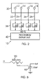
- Figure 2 illustrates a block diagram of a system 10 using the method of measuring current flows through individual fasteners in a multi-fastener composite structure joint.
- trace patterns 12, 14, 16, 18 are incorporated into a printed circuit board 20.
- PCB 20 has a trace pattern for every fastener that is to be queried in an area.
- Trace patterns 12-18 form Rogowski coil sensory circuits.
- the pattern of the fastener layout is known. All PCBs rely on multi-layer traces passing through a multi-layer board in specific patterns, however each PCB is custom made for each area to be queried.
- Each layer of PCB 20 goes through the same design and fabrication process so all of the traces are essentially balanced and the behavior of all coils will be similar because they are all built on the same board.
- the trace patterns 12-18 are designed using a standard PC-board Electronics Computer Aided Design (ECAD) package, such as PAR-EXTTM by Infinite GraphicsTM of Minneapolis, Minnesota.
- ECAD Electronics Computer Aided Design
- Using the multilayer board technology of PCBs allow the use of multiple signal layers with dielectric core layers to support the winding of the (nearly-concentric but opposing direction) traces.
- trace patterns 12-18 form an array of Rogowski coil sensory circuits 12-18 with each circuit surrounding a different fastener in a multi-fastener structural composite joint (or any other component for which the measurement of current flow is desired). Although four Rogowski coil sensory circuits 12-18 are shown, the number of circuit traces can be more than or less than four.
- Rogowski coil sensory circuits 12-18 are wound so that the signal response of the circuit to the area under measurement is maximized while the response to magnetic fields external to the circuit is minimized.
- the use of PCB 20 provides inherent precision in terms of the impedances of the circuits and the geometries of the copper traces and dielectric regions.
- all of the Rogowski coil sensory circuits 12-18 for an array of fasteners are formed during the same manufacturing sequence with the same copper and dielectric materials, all circuit traces are inherently similar in geometry and material properties, thus improving the consistency of the sensing unit. It is important that the traces wrap around a maximized amount of area as the magnetic flux through that area is causing the induction of current onto the traces.
- Rogowski coil sensory circuits 12-18 detect the current on individual fasteners and each circuit 12-18 generates individual outputs (induced current vs. time histories) 22, 24, 26, 28 which are input into respective individual integrator circuits 30-36 in a passive integrator array 38.
- a large electrical pulse is sent through the fastener and generates magnetic fields due to the rapid changes in the pulse.
- Each integrator circuit 30-36 captures the transient pulses, i.e. the induced change in voltage, from PCB 20 and integrates the pulses into an array output 40 that is suitable for post-processing into the desired fastener electrical current profiles.
- Array output 40 is then transmitted to a processing/display unit 42, such as an oscilloscope or a network analyzer to be displayed.
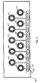
- FIG 3 illustrates a printed circuit board 41, etched with an array of Rogowski coil sensory circuits 43-63, for measuring current flows through individual fasteners in a multi-fastener structural composite joint by capturing the transient currents induced on Rogowski coils 43-63, which surround each fastener, by the magnetic fields emanating by the current flow in the devices.
- Rogowski coils are well known in the art for measuring current. See “High-Precision Rogowski Coils for Improved Relay Protection, Control and Measurements", pgs.7-8, by Ljubomir Kojovic.
- Each Rogowski coil is wound in a double helix pattern.
- the first helix encircles the fastener in a clockwise direction, while the second helix encircles the fastener in a counterclockwise direction.
- the two helixes are connected to each other at one end to form a continuous coil, and the other ends of the two helixes are connected to the input leads of the respective integrator circuit via connectors 65, 67 on PCB 41.
- each circuit is shown connected to a common ground 69, this is not necessary as twisted pair wires are used to minimize EMI from the wires connecting the PCB to the integrator.
- the direction of windings in the helical coils is oriented to respond to the magnetic field from current flow in the fastener such that a loop formed by a single helical coil around the fastener is eliminated. If the single loop was not eliminated, the loop would respond to magnetic fields due to current flow in the skin, introducing an unwanted response and contaminating the fastener current measurement.
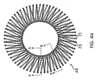
- Figure 4a illustrates an exploded view of a 4-signal-layer Rogowski coil design 44, etched into a PCB 41, having a first helix 71 and a second helix 73.
- Figure 4b illustrates a cross-section view of the Rogowski coil of Figure 4a taken along lines A-A
- Figure 4c illustrates a cross-section view of the Rogowski coil of Figure 4a taken along lines B-B.
- PCB 41 is comprised of first and third signal layers 46, 48 which represent second helix 73 while second and fourth signal layers 52, 54 represent first helix 71.
- a dielectric layer 50 approximately 90 mils in this case, is located between second and third signal layers 52, 48 of PCB 20 to provide increased separation (and thus cross-section) that is required in the sensing region for capturing the magnetic fields emanating from the current flow in the fasteners.
- the individual signal layers are connected with plated through-hole vias 64.
- PCB 41 comprise soldermask layers 56, 58 on the outer layers and first and second prepreg dielectric layers 60, 62 between first and second signal layers 46, 52 and third and fourth signal layers 48, 54 respectively.
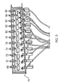
- FIG 5 illustrates a passive integrator array 75 (similar to 38 of Figure 2 ).
- Passive integrator array 75 comprises a separate integrator circuit for each fastener for capturing and analyzing the magnetically induced electrical fields emanating from the current flow in the respective fastener.
- Passive integrator array 75 comprises eleven (11) integrator circuits 68-88 (similar to 30-36). Although 11 integrator circuits are shown, passive integrator array can have more or less integrator circuits.
- Each integrator circuit captures the signal from a Rogowski coil on PCB 41 and translates the signal into the individual fastener currents and filters the noise emanating from skin currents and other Electromagnetic Interference.
- FIG 6 illustrates a circuit diagram of each passive integrator circuit in passive integrator array 75 of Figure 5 .
- the output of a Rogowski coil sensory circuit is input into a passive integrator circuit which, in this embodiment, comprises a 500 ohm variable resistor 90 and a 0.33 ⁇ F capacitor 92 that filters the noise emanating from skin currents and other Electromagnetic Interference.
- Each integrator circuit in Figure 5 integrates the outputs from the Rogowski coil sensory circuits into array output 40 that is transmitted to processing/display unit 42.
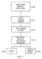
- FIG. 7 illustrates a flow chart illustrating the steps of measuring current flows through individual fasteners in a multi-fastener composite structure joint.
- the method begins in step S700 when PCB 20 is inserted inside the joint between two structures with the fastener extending through holes in the PCB 20, such that the fasteners are normal to PCB 20.
- step S701 the induced current in the fasteners is detected during a simulated lightning strike test, for example.
- the induced current is transmitted to passive integrator array 38. Induced current is not the current applied during test, but is the current that is exhibited between the two paths of each trace.
- Passive integrator array 38 captures the transient pulses, i.e.
- step S703 array output 40 is transmitted to processing/display unit 42, such as an oscilloscope or a network analyzer.
- processing/display unit 42 such as an oscilloscope or a network analyzer.
- step S704 output 40 is used to certify the joint design under test for an aircraft for safety.
- step S705 output 40 is used to improve the design on structures on an aircraft to prevent sparking from a lightning strike.
- current flows through individual fasteners in a multi-fastener structural composite joint are measured creating a baseline. By knowing how the currents are flowing during a lightning event, it can be determined whether or not any change in design or manufacture of a composite structure has modified the flow of current in such a way as to protect against or reduce damage from a lightning strike.
- Figure 8 is a graph illustrating an example of an array output displayed on processing/display unit 42.
- the graph shows the current flows through 8 fasteners F1-F8.
- the reduced current peak for the lightning-struck fastener (fastener F6) and increased current levels for the adjacent fasteners to fastener F6 are shown in the graph.
Landscapes
- Engineering & Computer Science (AREA)
- Power Engineering (AREA)
- Physics & Mathematics (AREA)
- General Physics & Mathematics (AREA)
- Measuring Instrument Details And Bridges, And Automatic Balancing Devices (AREA)
- Measurement Of Current Or Voltage (AREA)
- Measurement Of Resistance Or Impedance (AREA)
Claims (10)
- Procédé de mesure de débits de courant à travers des fixations (3) dans un joint composite de multi-structure (2), comprenat :insérer une carte de circuit imprimé (20) entre au moins deux structures (5, 6), la carte de circuit imprimé étant gravée avec au moins un circuit de détection à bobines de Rogowski (12), les deux structures étant reliées avec au moins une fixation (3) s'étendant à travers le au moins un circuit de détection à bobines de Rogowski dans la carte de circuit imprimé ;détecter le courant dans la au moins une fixation en utilisant la bobine de Rogowski correspondante ;transmettre le courant détecté de chaque fixation à un circuit d'intégration passif correspondant (30) pour capturer des impulsions transitoires et intégrer les impulsions transitoires capturées dans une sortie (40) ; ettransmettre la sortie à une unité de traitement (42).
- Procédé selon la revendication 1, dans lequel les au moins deux structures sont jointes par au moins deux fixations, chaque fixation s'étendant à travers un circuit de détection à bobines de Rogowski correspondant, les impulsions transitoires capturées étant transmises au groupement de circuits d'intégration passif correspondant, la sortie de l'intégrateur de chaque intégrateur passif étant transmise comme une sortie de groupement à l'unité de traitement, pour mesurer simultanément les débits de courant à travers les au moins deux fixations.
- Procédé selon la revendication 2, dans lequel les fixations sont disposées selon la normale à la carte de circuit imprimée.
- Procédé selon la revendication 3, dans lequel l'unité de traitement est au moins un d'un analyseur de réseau ou d'un oscilloscope.
- Procédé selon la revendication 1, dans lequel le circuit d'intégration passif est constitué par au moins une résistance variable (90) reliée à un condensateur (92) pour le filtrage de bruits émanent de courants de peau.
- Procédé selon la revendication 1, dans lequel la détection du courant comprend la détection d'une impulsion électrique qui est transmise par la au moins une fixation, et où l'impulsion électrique simule un coup de foudre.
- Système pour la mesure simultanée de débits de courant à travers des fixations (3) dans un joint composite de multi-structure (2), comprenant :une carte de circuit imprimé (20) gravée avec au moins deux circuits de détection à bobines de Rogowski (12, 14), chaque bobine de Rogowski étant enroulée selon un motif à hélice double, la carte de circuit imprimée étant insérée à l'intérieur du joint entre au moins deux structures (5, 6) reliées par au moins deux fixations (3), les au moins deux fixations s'étendant chacune à travers un circuit de détection à bobines de Rogowski correspondant ;un groupement d'intégrateurs passifs (38) ayant au moins deux circuits d'intégrateur passifs (30, 32) pour recevoir une sortie correspondante (22, 24) de chaque circuit de détection à bobines de Rogowski (12, 14) et pour intégrer les sorties dans une sortie de groupement (40) ; etune unité de traitement (42) pour afficher la sortie de groupement.
- Système selon la revendication 7, dans lequel les sorties sont des impulsions transitoires de la carte de circuit imprimé provoquées par une impulsion électrique transmise par les au moins deux fixations, et où l'impulsion électrique simule un coup de foudre.
- Système selon la revendication 7, dans lequel l'unité de traitement est au moins un d'un analyseur de réseau ou d'un oscilloscope.
- Système selon la revendication 7, dans lequel le au moins un circuit d'intégrateur passif comprend une résistance variable (90) connectée à un condensateur (92).
Applications Claiming Priority (1)
| Application Number | Priority Date | Filing Date | Title |
|---|---|---|---|
| US11/498,634 US7532000B2 (en) | 2006-08-03 | 2006-08-03 | Method and system for measurement of current flows in fastener arrays |
Publications (3)
| Publication Number | Publication Date |
|---|---|
| EP1887366A2 EP1887366A2 (fr) | 2008-02-13 |
| EP1887366A3 EP1887366A3 (fr) | 2012-01-04 |
| EP1887366B1 true EP1887366B1 (fr) | 2013-07-17 |
Family
ID=38698447
Family Applications (1)
| Application Number | Title | Priority Date | Filing Date |
|---|---|---|---|
| EP07253044.7A Active EP1887366B1 (fr) | 2006-08-03 | 2007-08-02 | Procédé et système pour la mesure de débits de courant dans des réseaux de fixations |
Country Status (3)
| Country | Link |
|---|---|
| US (1) | US7532000B2 (fr) |
| EP (1) | EP1887366B1 (fr) |
| JP (1) | JP5142615B2 (fr) |
Families Citing this family (41)
| Publication number | Priority date | Publication date | Assignee | Title |
|---|---|---|---|---|
| US8398170B2 (en) * | 2006-10-06 | 2013-03-19 | Brock Walker | Active response seating system |
| FR2920881B1 (fr) * | 2007-09-10 | 2010-03-05 | Socomec Sa | DISPOSITIF DE MESURE DE l'INTENSITE D'UN COURANT ELECTRIQUE ET APPAREIL ELECTRIQUE COMPORTANT UN TEL DISPOSITIF. |
| US9664711B2 (en) * | 2009-07-31 | 2017-05-30 | Pulse Electronics, Inc. | Current sensing devices and methods |
| US9823274B2 (en) * | 2009-07-31 | 2017-11-21 | Pulse Electronics, Inc. | Current sensing inductive devices |
| US9151782B2 (en) * | 2009-07-31 | 2015-10-06 | Pulse Electronics, Inc. | Current sensing devices and methods |
| US8264215B1 (en) * | 2009-12-10 | 2012-09-11 | The Boeing Company | Onboard electrical current sensing system |
| JP5705518B2 (ja) * | 2010-12-02 | 2015-04-22 | 三菱航空機株式会社 | 電流計測方法 |
| JP5820164B2 (ja) * | 2011-07-01 | 2015-11-24 | 東光東芝メーターシステムズ株式会社 | 電流検出装置およびこれを用いた電力量計 |
| US8872611B2 (en) * | 2011-08-18 | 2014-10-28 | General Electric Company | Rogowski coil assemblies and methods for providing the same |
| US8912807B2 (en) | 2011-09-09 | 2014-12-16 | General Electric Company | Sensor devices and methods for use in sensing current through a conductor |
| US9075091B2 (en) | 2011-09-09 | 2015-07-07 | General Electric Company | Sensor devices and methods for use in sensing current through a conductor |
| US9429595B2 (en) | 2011-09-09 | 2016-08-30 | Aclara Meters Llc | Sensor devices and methods for use in sensing current through a conductor |
| US9081040B2 (en) | 2011-09-09 | 2015-07-14 | General Electric Company | Sensor devices and methods for use in sensing current through a conductor |
| US8829888B2 (en) | 2011-09-09 | 2014-09-09 | General Electric Company | Sensor devices and methods for use in sensing current through a conductor |
| US9304149B2 (en) | 2012-05-31 | 2016-04-05 | Pulse Electronics, Inc. | Current sensing devices and methods |
| US20140117022A1 (en) * | 2012-10-30 | 2014-05-01 | The Boeing Company | Composite Structures Having Bondlines with Matched Electrical Conductivity |
| US20140125446A1 (en) | 2012-11-07 | 2014-05-08 | Pulse Electronics, Inc. | Substrate inductive device methods and apparatus |
| EP2730508B1 (fr) * | 2012-11-12 | 2016-09-14 | Airbus Operations GmbH | Panneau de carénage/garniture et procédé de mesure de la résistance de liaison électrique d'un panneau de carénage/garniture |
| US20140167787A1 (en) * | 2012-12-14 | 2014-06-19 | Schneider Electric USA, Inc. | Branch Circuit Current Monitor |
| JP5860010B2 (ja) * | 2013-08-29 | 2016-02-16 | 富士重工業株式会社 | 電流測定装置及び電流測定方法 |
| US9676351B2 (en) | 2013-10-11 | 2017-06-13 | The Boeing Company | Modular equipment center solid state primary power switching network |
| US9561761B2 (en) | 2013-10-11 | 2017-02-07 | The Boeing Company | Modular equipment center zonal standalone power system control architecture |
| US9561867B2 (en) | 2013-10-11 | 2017-02-07 | The Boeing Company | Modular equipment center lightning threat reduction architecture |
| US9413162B2 (en) | 2013-10-11 | 2016-08-09 | The Boeing Company | Modular equipment center distributed independent protections |
| US9561760B2 (en) | 2013-10-11 | 2017-02-07 | The Boeing Company | Modular equipment center distributed equipment packaging truss |
| US9183983B2 (en) | 2013-10-11 | 2015-11-10 | The Boeing Company | Modular equipment center integrated truss sensors |
| US9511728B2 (en) | 2013-10-11 | 2016-12-06 | The Boeing Company | Modular equipment center distributed primary power architecture |
| CA2933162C (fr) | 2013-10-11 | 2019-09-10 | The Boeing Company | Reseau de commutation de puissance primaire a semi-conducteurs pour centres d'equipement modulaires |
| US9533636B2 (en) | 2013-10-11 | 2017-01-03 | The Boeing Company | Remote modular equipment center architecture |
| JP6267976B2 (ja) * | 2014-01-27 | 2018-01-24 | 三菱航空機株式会社 | 航空機の耐雷適合性の試験対象の決定方法、および耐雷適合性証明方法 |
| US9488609B2 (en) * | 2014-02-06 | 2016-11-08 | The Boeing Company | Determination of anisotropic conduction characteristics |
| US9739818B2 (en) | 2014-03-12 | 2017-08-22 | The Boeing Company | Electromagnetic effect testing |
| US9671434B2 (en) | 2014-08-08 | 2017-06-06 | Aclara Meters Llc | Sensor devices and methods for use in sensing current through a conductor |
| US9588147B2 (en) * | 2015-02-04 | 2017-03-07 | 3M Innovative Properties Company | Electronic integrator for Rogowski coil sensors |
| EP3174086A1 (fr) * | 2015-11-26 | 2017-05-31 | Eidgenössische Materialprüfungs- und Forschungsanstalt EMPA | Dispositif complémentaire de détecteur pour établissement de spectroscopie |
| KR101984073B1 (ko) * | 2018-06-15 | 2019-05-31 | 주식회사 엘피에스코리아 | 로고스키 코일을 이용한 임펄스 전류측정장치 |
| CN109884378A (zh) * | 2019-03-08 | 2019-06-14 | 南京导纳能科技有限公司 | 一种基于pcb型罗氏线圈的避雷器动作电流测量电路 |
| CN111609957B (zh) * | 2020-05-22 | 2021-04-23 | 西安交通大学 | 雷击对碳纤维层合板冲击力和响应时间的测量装置及方法 |
| CN111609958B (zh) * | 2020-05-22 | 2021-04-27 | 西安交通大学 | 碳纤维层合板雷击冲击力和雷电断裂损伤测量装置和方法 |
| CN114325048A (zh) * | 2021-12-27 | 2022-04-12 | 南方电网数字电网研究院有限公司 | 一种自取能的柔性电流测量装置 |
| US12571818B2 (en) | 2023-03-31 | 2026-03-10 | Schneider Electric USA, Inc. | PCB trace current sensor for energy measurement |
Family Cites Families (18)
| Publication number | Priority date | Publication date | Assignee | Title |
|---|---|---|---|---|
| JPS585668A (ja) * | 1981-06-30 | 1983-01-13 | Fujitsu Ltd | 検出コイル |
| US4905931A (en) * | 1988-02-18 | 1990-03-06 | The Boeing Company | Arc suppression around fasteners |
| JPH0616455Y2 (ja) * | 1989-02-08 | 1994-04-27 | 中国電力株式会社 | 雷サージレコーダ |
| JPH0742144Y2 (ja) * | 1991-05-21 | 1995-09-27 | 北陸電力株式会社 | 雷サージ検出装置 |
| FR2695482B1 (fr) * | 1992-09-10 | 1994-10-21 | Alsthom Gec | Dispositif de mesure utilisant une bobine des Rogowski. |
| US5548523A (en) * | 1994-06-20 | 1996-08-20 | Eaton Corporation | Monitoring device secured to power distribution system conductors |
| JP3786223B2 (ja) * | 1996-09-12 | 2006-06-14 | 富士電機機器制御株式会社 | 回路遮断器の過電流検出用変流器 |
| JPH10197652A (ja) * | 1997-01-13 | 1998-07-31 | Tokyo Electric Power Co Inc:The | 配電線雷観測システム |
| JP3945087B2 (ja) * | 1999-09-29 | 2007-07-18 | 三菱電機株式会社 | ロゴスキーコイル |
| JP2001218322A (ja) * | 2000-02-02 | 2001-08-10 | Nissin Electric Co Ltd | 管路の部分放電位置標定方法及び部分放電位置標定装置 |
| US6313623B1 (en) * | 2000-02-03 | 2001-11-06 | Mcgraw-Edison Company | High precision rogowski coil |
| JP2003130894A (ja) * | 2001-10-29 | 2003-05-08 | Toshiba Corp | 変流器 |
| US6680608B2 (en) * | 2002-02-27 | 2004-01-20 | Mcgraw-Edison Company | Measuring current through an electrical conductor |
| US6825651B2 (en) * | 2002-04-12 | 2004-11-30 | Hewlett-Packard Development Company, L.P. | Test method for characterizing currents associated with powered components in an electronic system |
| JP2004119926A (ja) * | 2002-09-30 | 2004-04-15 | Toshiba Corp | 変流器及び変流器システム |
| US6914427B2 (en) * | 2003-03-14 | 2005-07-05 | The Boeing Company | Eddy current probe having sensing elements defined by first and second elongated coils and an associated inspection method |
| JP4456975B2 (ja) * | 2004-10-14 | 2010-04-28 | 中国電力株式会社 | ガス絶縁開閉装置の事故検出装置 |
| US7227442B2 (en) * | 2005-04-01 | 2007-06-05 | Schweitzer Engineering Laboratories, Inc. | Precision printed circuit board based rogowski coil and method for manufacturing same |
-
2006
- 2006-08-03 US US11/498,634 patent/US7532000B2/en active Active
-
2007
- 2007-07-26 JP JP2007193971A patent/JP5142615B2/ja active Active
- 2007-08-02 EP EP07253044.7A patent/EP1887366B1/fr active Active
Also Published As
| Publication number | Publication date |
|---|---|
| US7532000B2 (en) | 2009-05-12 |
| EP1887366A3 (fr) | 2012-01-04 |
| JP2008039775A (ja) | 2008-02-21 |
| JP5142615B2 (ja) | 2013-02-13 |
| EP1887366A2 (fr) | 2008-02-13 |
| US20080036448A1 (en) | 2008-02-14 |
Similar Documents
| Publication | Publication Date | Title |
|---|---|---|
| EP1887366B1 (fr) | Procédé et système pour la mesure de débits de courant dans des réseaux de fixations | |
| EP1264188B1 (fr) | Enroulement de rogowski de grande precision | |
| EP3508864B1 (fr) | Structure de capteur de courant de décalage | |
| Kojovic | PCB Rogowski coils benefit relay protection | |
| EP1277060B1 (fr) | Dispositif de mesure de courant | |
| EP2108965B1 (fr) | Capteur de tension/courant en fréquence radio orthogonale doté d'une plage dynamique étendue | |
| EP2699064A2 (fr) | Technologie de capteur RF planair | |
| US9035736B2 (en) | Magnetic device having integrated current sensing element and methods of assembling same | |
| Kuwabara et al. | Implementation and performance of a current sensor for a laminated bus bar | |
| Khater | High-speed printed circuit boards: A tutorial | |
| DE69905044T2 (de) | Geschichteter-stromsensor | |
| US9575097B2 (en) | Specimen and current measuring method | |
| JP2013130571A (ja) | 電流センサ | |
| CN101515018A (zh) | 电路检测回路及制造使用方法 | |
| US6727774B1 (en) | Bypass capacitor methods for achieving a desired value of electrical impedance between parallel planar conductors of an electrical power distribution structure, and associated electrical power distribution structures | |
| CN104078194B (zh) | 具有一体化电流感测元件的磁性装置及其组装方法 | |
| CN110701986B (zh) | 电磁感应式位置传感器的传感器基板及其制造方法 | |
| EP3940394A1 (fr) | Capteur de courant électrique | |
| Leininger et al. | Advanced grounding methods in the presence of carbon fibre reinforced plastic structures | |
| Wang et al. | Coupling between differential signals and the DC power-bus in multilayer PCBs | |
| US20120032700A1 (en) | Multilayer wiring board and method for evaluating multilayer wiring board | |
| US8704102B2 (en) | Printed flexible multilayer twisted-pair shielded high speed data cable | |
| US7202756B2 (en) | Electromagnetic coupler with direct current signal detection | |
| US9958496B2 (en) | Layer-layer registration coupon for printed circuit boards | |
| US20040118597A1 (en) | Apparatus and method for improving coupling across plane discontinuities on circuit boards |
Legal Events
| Date | Code | Title | Description |
|---|---|---|---|
| PUAI | Public reference made under article 153(3) epc to a published international application that has entered the european phase |
Free format text: ORIGINAL CODE: 0009012 |
|
| 17P | Request for examination filed |
Effective date: 20070816 |
|
| AK | Designated contracting states |
Kind code of ref document: A2 Designated state(s): AT BE BG CH CY CZ DE DK EE ES FI FR GB GR HU IE IS IT LI LT LU LV MC MT NL PL PT RO SE SI SK TR |
|
| AX | Request for extension of the european patent |
Extension state: AL BA HR MK YU |
|
| PUAL | Search report despatched |
Free format text: ORIGINAL CODE: 0009013 |
|
| AK | Designated contracting states |
Kind code of ref document: A3 Designated state(s): AT BE BG CH CY CZ DE DK EE ES FI FR GB GR HU IE IS IT LI LT LU LV MC MT NL PL PT RO SE SI SK TR |
|
| AX | Request for extension of the european patent |
Extension state: AL BA HR MK RS |
|
| RIC1 | Information provided on ipc code assigned before grant |
Ipc: G01R 31/00 20060101ALN20111201BHEP Ipc: G01R 15/18 20060101AFI20111201BHEP |
|
| AKX | Designation fees paid |
Designated state(s): AT BE BG CH CY CZ DE DK EE ES FI FR GB GR HU IE IS IT LI LT LU LV MC MT NL PL PT RO SE SI SK TR |
|
| RIC1 | Information provided on ipc code assigned before grant |
Ipc: G01R 31/00 20060101ALN20121219BHEP Ipc: G01R 15/18 20060101AFI20121219BHEP |
|
| GRAP | Despatch of communication of intention to grant a patent |
Free format text: ORIGINAL CODE: EPIDOSNIGR1 |
|
| GRAS | Grant fee paid |
Free format text: ORIGINAL CODE: EPIDOSNIGR3 |
|
| GRAA | (expected) grant |
Free format text: ORIGINAL CODE: 0009210 |
|
| AK | Designated contracting states |
Kind code of ref document: B1 Designated state(s): AT BE BG CH CY CZ DE DK EE ES FI FR GB GR HU IE IS IT LI LT LU LV MC MT NL PL PT RO SE SI SK TR |
|
| REG | Reference to a national code |
Ref country code: GB Ref legal event code: FG4D |
|
| REG | Reference to a national code |
Ref country code: CH Ref legal event code: EP |
|
| REG | Reference to a national code |
Ref country code: IE Ref legal event code: FG4D |
|
| REG | Reference to a national code |
Ref country code: AT Ref legal event code: REF Ref document number: 622521 Country of ref document: AT Kind code of ref document: T Effective date: 20130815 |
|
| REG | Reference to a national code |
Ref country code: DE Ref legal event code: R096 Ref document number: 602007031662 Country of ref document: DE Effective date: 20130912 |
|
| REG | Reference to a national code |
Ref country code: AT Ref legal event code: MK05 Ref document number: 622521 Country of ref document: AT Kind code of ref document: T Effective date: 20130717 |
|
| REG | Reference to a national code |
Ref country code: NL Ref legal event code: VDEP Effective date: 20130717 |
|
| REG | Reference to a national code |
Ref country code: LT Ref legal event code: MG4D |
|
| PG25 | Lapsed in a contracting state [announced via postgrant information from national office to epo] |
Ref country code: LT Free format text: LAPSE BECAUSE OF FAILURE TO SUBMIT A TRANSLATION OF THE DESCRIPTION OR TO PAY THE FEE WITHIN THE PRESCRIBED TIME-LIMIT Effective date: 20130717 Ref country code: IS Free format text: LAPSE BECAUSE OF FAILURE TO SUBMIT A TRANSLATION OF THE DESCRIPTION OR TO PAY THE FEE WITHIN THE PRESCRIBED TIME-LIMIT Effective date: 20131117 Ref country code: AT Free format text: LAPSE BECAUSE OF FAILURE TO SUBMIT A TRANSLATION OF THE DESCRIPTION OR TO PAY THE FEE WITHIN THE PRESCRIBED TIME-LIMIT Effective date: 20130717 Ref country code: CY Free format text: LAPSE BECAUSE OF FAILURE TO SUBMIT A TRANSLATION OF THE DESCRIPTION OR TO PAY THE FEE WITHIN THE PRESCRIBED TIME-LIMIT Effective date: 20130703 Ref country code: SE Free format text: LAPSE BECAUSE OF FAILURE TO SUBMIT A TRANSLATION OF THE DESCRIPTION OR TO PAY THE FEE WITHIN THE PRESCRIBED TIME-LIMIT Effective date: 20130717 Ref country code: PT Free format text: LAPSE BECAUSE OF FAILURE TO SUBMIT A TRANSLATION OF THE DESCRIPTION OR TO PAY THE FEE WITHIN THE PRESCRIBED TIME-LIMIT Effective date: 20131118 Ref country code: BE Free format text: LAPSE BECAUSE OF FAILURE TO SUBMIT A TRANSLATION OF THE DESCRIPTION OR TO PAY THE FEE WITHIN THE PRESCRIBED TIME-LIMIT Effective date: 20130717 |
|
| PG25 | Lapsed in a contracting state [announced via postgrant information from national office to epo] |
Ref country code: LV Free format text: LAPSE BECAUSE OF FAILURE TO SUBMIT A TRANSLATION OF THE DESCRIPTION OR TO PAY THE FEE WITHIN THE PRESCRIBED TIME-LIMIT Effective date: 20130717 Ref country code: NL Free format text: LAPSE BECAUSE OF FAILURE TO SUBMIT A TRANSLATION OF THE DESCRIPTION OR TO PAY THE FEE WITHIN THE PRESCRIBED TIME-LIMIT Effective date: 20130717 Ref country code: FI Free format text: LAPSE BECAUSE OF FAILURE TO SUBMIT A TRANSLATION OF THE DESCRIPTION OR TO PAY THE FEE WITHIN THE PRESCRIBED TIME-LIMIT Effective date: 20130717 Ref country code: GR Free format text: LAPSE BECAUSE OF FAILURE TO SUBMIT A TRANSLATION OF THE DESCRIPTION OR TO PAY THE FEE WITHIN THE PRESCRIBED TIME-LIMIT Effective date: 20131018 Ref country code: PL Free format text: LAPSE BECAUSE OF FAILURE TO SUBMIT A TRANSLATION OF THE DESCRIPTION OR TO PAY THE FEE WITHIN THE PRESCRIBED TIME-LIMIT Effective date: 20130717 Ref country code: SI Free format text: LAPSE BECAUSE OF FAILURE TO SUBMIT A TRANSLATION OF THE DESCRIPTION OR TO PAY THE FEE WITHIN THE PRESCRIBED TIME-LIMIT Effective date: 20130717 Ref country code: ES Free format text: LAPSE BECAUSE OF FAILURE TO SUBMIT A TRANSLATION OF THE DESCRIPTION OR TO PAY THE FEE WITHIN THE PRESCRIBED TIME-LIMIT Effective date: 20131028 |
|
| PG25 | Lapsed in a contracting state [announced via postgrant information from national office to epo] |
Ref country code: CY Free format text: LAPSE BECAUSE OF FAILURE TO SUBMIT A TRANSLATION OF THE DESCRIPTION OR TO PAY THE FEE WITHIN THE PRESCRIBED TIME-LIMIT Effective date: 20130717 |
|
| REG | Reference to a national code |
Ref country code: CH Ref legal event code: PL |
|
| PG25 | Lapsed in a contracting state [announced via postgrant information from national office to epo] |
Ref country code: EE Free format text: LAPSE BECAUSE OF FAILURE TO SUBMIT A TRANSLATION OF THE DESCRIPTION OR TO PAY THE FEE WITHIN THE PRESCRIBED TIME-LIMIT Effective date: 20130717 Ref country code: CZ Free format text: LAPSE BECAUSE OF FAILURE TO SUBMIT A TRANSLATION OF THE DESCRIPTION OR TO PAY THE FEE WITHIN THE PRESCRIBED TIME-LIMIT Effective date: 20130717 Ref country code: LI Free format text: LAPSE BECAUSE OF NON-PAYMENT OF DUE FEES Effective date: 20130831 Ref country code: CH Free format text: LAPSE BECAUSE OF NON-PAYMENT OF DUE FEES Effective date: 20130831 Ref country code: SK Free format text: LAPSE BECAUSE OF FAILURE TO SUBMIT A TRANSLATION OF THE DESCRIPTION OR TO PAY THE FEE WITHIN THE PRESCRIBED TIME-LIMIT Effective date: 20130717 Ref country code: RO Free format text: LAPSE BECAUSE OF FAILURE TO SUBMIT A TRANSLATION OF THE DESCRIPTION OR TO PAY THE FEE WITHIN THE PRESCRIBED TIME-LIMIT Effective date: 20130717 Ref country code: DK Free format text: LAPSE BECAUSE OF FAILURE TO SUBMIT A TRANSLATION OF THE DESCRIPTION OR TO PAY THE FEE WITHIN THE PRESCRIBED TIME-LIMIT Effective date: 20130717 Ref country code: MC Free format text: LAPSE BECAUSE OF FAILURE TO SUBMIT A TRANSLATION OF THE DESCRIPTION OR TO PAY THE FEE WITHIN THE PRESCRIBED TIME-LIMIT Effective date: 20130717 |
|
| REG | Reference to a national code |
Ref country code: IE Ref legal event code: MM4A |
|
| PLBE | No opposition filed within time limit |
Free format text: ORIGINAL CODE: 0009261 |
|
| STAA | Information on the status of an ep patent application or granted ep patent |
Free format text: STATUS: NO OPPOSITION FILED WITHIN TIME LIMIT |
|
| PG25 | Lapsed in a contracting state [announced via postgrant information from national office to epo] |
Ref country code: IT Free format text: LAPSE BECAUSE OF FAILURE TO SUBMIT A TRANSLATION OF THE DESCRIPTION OR TO PAY THE FEE WITHIN THE PRESCRIBED TIME-LIMIT Effective date: 20130717 |
|
| 26N | No opposition filed |
Effective date: 20140422 |
|
| PG25 | Lapsed in a contracting state [announced via postgrant information from national office to epo] |
Ref country code: IE Free format text: LAPSE BECAUSE OF NON-PAYMENT OF DUE FEES Effective date: 20130802 |
|
| REG | Reference to a national code |
Ref country code: DE Ref legal event code: R097 Ref document number: 602007031662 Country of ref document: DE Effective date: 20140422 |
|
| PG25 | Lapsed in a contracting state [announced via postgrant information from national office to epo] |
Ref country code: TR Free format text: LAPSE BECAUSE OF FAILURE TO SUBMIT A TRANSLATION OF THE DESCRIPTION OR TO PAY THE FEE WITHIN THE PRESCRIBED TIME-LIMIT Effective date: 20130717 Ref country code: MT Free format text: LAPSE BECAUSE OF FAILURE TO SUBMIT A TRANSLATION OF THE DESCRIPTION OR TO PAY THE FEE WITHIN THE PRESCRIBED TIME-LIMIT Effective date: 20130717 |
|
| PG25 | Lapsed in a contracting state [announced via postgrant information from national office to epo] |
Ref country code: HU Free format text: LAPSE BECAUSE OF FAILURE TO SUBMIT A TRANSLATION OF THE DESCRIPTION OR TO PAY THE FEE WITHIN THE PRESCRIBED TIME-LIMIT; INVALID AB INITIO Effective date: 20070802 Ref country code: BG Free format text: LAPSE BECAUSE OF FAILURE TO SUBMIT A TRANSLATION OF THE DESCRIPTION OR TO PAY THE FEE WITHIN THE PRESCRIBED TIME-LIMIT Effective date: 20130717 Ref country code: LU Free format text: LAPSE BECAUSE OF NON-PAYMENT OF DUE FEES Effective date: 20130802 |
|
| REG | Reference to a national code |
Ref country code: FR Ref legal event code: PLFP Year of fee payment: 10 |
|
| REG | Reference to a national code |
Ref country code: FR Ref legal event code: PLFP Year of fee payment: 11 |
|
| REG | Reference to a national code |
Ref country code: FR Ref legal event code: PLFP Year of fee payment: 12 |
|
| P01 | Opt-out of the competence of the unified patent court (upc) registered |
Effective date: 20230516 |
|
| PGFP | Annual fee paid to national office [announced via postgrant information from national office to epo] |
Ref country code: DE Payment date: 20250827 Year of fee payment: 19 |
|
| PGFP | Annual fee paid to national office [announced via postgrant information from national office to epo] |
Ref country code: GB Payment date: 20250827 Year of fee payment: 19 |
|
| PGFP | Annual fee paid to national office [announced via postgrant information from national office to epo] |
Ref country code: FR Payment date: 20250825 Year of fee payment: 19 |