EP1889730A1 - Cylindre à graver pour héliogravure et son procédé de production - Google Patents
Cylindre à graver pour héliogravure et son procédé de production Download PDFInfo
- Publication number
- EP1889730A1 EP1889730A1 EP06756508A EP06756508A EP1889730A1 EP 1889730 A1 EP1889730 A1 EP 1889730A1 EP 06756508 A EP06756508 A EP 06756508A EP 06756508 A EP06756508 A EP 06756508A EP 1889730 A1 EP1889730 A1 EP 1889730A1
- Authority
- EP
- European Patent Office
- Prior art keywords
- layer
- metal
- gravure
- metal carbide
- diamond
- Prior art date
- Legal status (The legal status is an assumption and is not a legal conclusion. Google has not performed a legal analysis and makes no representation as to the accuracy of the status listed.)
- Withdrawn
Links
- 238000000034 method Methods 0.000 title claims abstract description 43
- 229910052751 metal Inorganic materials 0.000 claims abstract description 115
- 239000002184 metal Substances 0.000 claims abstract description 115
- OKTJSMMVPCPJKN-UHFFFAOYSA-N Carbon Chemical compound [C] OKTJSMMVPCPJKN-UHFFFAOYSA-N 0.000 claims abstract description 46
- 229910052799 carbon Inorganic materials 0.000 claims abstract description 46
- 238000007747 plating Methods 0.000 claims abstract description 44
- RYGMFSIKBFXOCR-UHFFFAOYSA-N Copper Chemical compound [Cu] RYGMFSIKBFXOCR-UHFFFAOYSA-N 0.000 claims abstract description 42
- 229910052802 copper Inorganic materials 0.000 claims abstract description 42
- 239000010949 copper Substances 0.000 claims abstract description 42
- 239000011248 coating agent Substances 0.000 claims abstract description 31
- 238000000576 coating method Methods 0.000 claims abstract description 31
- 239000011651 chromium Substances 0.000 claims description 24
- VYZAMTAEIAYCRO-UHFFFAOYSA-N Chromium Chemical compound [Cr] VYZAMTAEIAYCRO-UHFFFAOYSA-N 0.000 claims description 19
- 229910052804 chromium Inorganic materials 0.000 claims description 19
- 238000004544 sputter deposition Methods 0.000 claims description 14
- WFKWXMTUELFFGS-UHFFFAOYSA-N tungsten Chemical compound [W] WFKWXMTUELFFGS-UHFFFAOYSA-N 0.000 claims description 11
- 229910052721 tungsten Inorganic materials 0.000 claims description 11
- 239000010937 tungsten Substances 0.000 claims description 11
- 239000010936 titanium Substances 0.000 claims description 10
- 238000005530 etching Methods 0.000 claims description 9
- 239000000203 mixture Substances 0.000 claims description 8
- XUIMIQQOPSSXEZ-UHFFFAOYSA-N Silicon Chemical compound [Si] XUIMIQQOPSSXEZ-UHFFFAOYSA-N 0.000 claims description 5
- RTAQQCXQSZGOHL-UHFFFAOYSA-N Titanium Chemical compound [Ti] RTAQQCXQSZGOHL-UHFFFAOYSA-N 0.000 claims description 5
- 229910052710 silicon Inorganic materials 0.000 claims description 5
- 239000010703 silicon Substances 0.000 claims description 5
- 229910052719 titanium Inorganic materials 0.000 claims description 5
- VSZWPYCFIRKVQL-UHFFFAOYSA-N selanylidenegallium;selenium Chemical compound [Se].[Se]=[Ga].[Se]=[Ga] VSZWPYCFIRKVQL-UHFFFAOYSA-N 0.000 claims description 4
- 229910052715 tantalum Inorganic materials 0.000 claims description 4
- GUVRBAGPIYLISA-UHFFFAOYSA-N tantalum atom Chemical compound [Ta] GUVRBAGPIYLISA-UHFFFAOYSA-N 0.000 claims description 4
- 150000002739 metals Chemical class 0.000 claims description 3
- 239000010410 layer Substances 0.000 abstract description 106
- 238000007639 printing Methods 0.000 abstract description 13
- 239000011247 coating layer Substances 0.000 abstract description 10
- 231100000252 nontoxic Toxicity 0.000 abstract 1
- 230000003000 nontoxic effect Effects 0.000 abstract 1
- 239000010408 film Substances 0.000 description 20
- 230000015572 biosynthetic process Effects 0.000 description 19
- 239000007789 gas Substances 0.000 description 14
- 239000000463 material Substances 0.000 description 10
- 239000010409 thin film Substances 0.000 description 10
- XKRFYHLGVUSROY-UHFFFAOYSA-N Argon Chemical compound [Ar] XKRFYHLGVUSROY-UHFFFAOYSA-N 0.000 description 8
- 150000002500 ions Chemical class 0.000 description 7
- 239000000758 substrate Substances 0.000 description 7
- 238000007733 ion plating Methods 0.000 description 6
- UONOETXJSWQNOL-UHFFFAOYSA-N tungsten carbide Chemical compound [W+]#[C-] UONOETXJSWQNOL-UHFFFAOYSA-N 0.000 description 5
- XEEYBQQBJWHFJM-UHFFFAOYSA-N Iron Chemical compound [Fe] XEEYBQQBJWHFJM-UHFFFAOYSA-N 0.000 description 4
- 229910052786 argon Inorganic materials 0.000 description 4
- 239000010953 base metal Substances 0.000 description 4
- 238000010894 electron beam technology Methods 0.000 description 4
- 238000004519 manufacturing process Methods 0.000 description 4
- 239000007787 solid Substances 0.000 description 4
- 239000004215 Carbon black (E152) Substances 0.000 description 3
- 238000005299 abrasion Methods 0.000 description 3
- 229910052782 aluminium Inorganic materials 0.000 description 3
- XAGFODPZIPBFFR-UHFFFAOYSA-N aluminium Chemical compound [Al] XAGFODPZIPBFFR-UHFFFAOYSA-N 0.000 description 3
- 229930195733 hydrocarbon Natural products 0.000 description 3
- 150000002430 hydrocarbons Chemical class 0.000 description 3
- 239000005026 oriented polypropylene Substances 0.000 description 3
- 238000005268 plasma chemical vapour deposition Methods 0.000 description 3
- 239000000243 solution Substances 0.000 description 3
- 238000001771 vacuum deposition Methods 0.000 description 3
- ATUOYWHBWRKTHZ-UHFFFAOYSA-N Propane Chemical compound CCC ATUOYWHBWRKTHZ-UHFFFAOYSA-N 0.000 description 2
- JOPOVCBBYLSVDA-UHFFFAOYSA-N chromium(6+) Chemical compound [Cr+6] JOPOVCBBYLSVDA-UHFFFAOYSA-N 0.000 description 2
- 238000010586 diagram Methods 0.000 description 2
- 229910003460 diamond Inorganic materials 0.000 description 2
- 239000010432 diamond Substances 0.000 description 2
- 230000000694 effects Effects 0.000 description 2
- 238000001704 evaporation Methods 0.000 description 2
- 238000002347 injection Methods 0.000 description 2
- 239000007924 injection Substances 0.000 description 2
- 229910052742 iron Inorganic materials 0.000 description 2
- VNWKTOKETHGBQD-UHFFFAOYSA-N methane Chemical compound C VNWKTOKETHGBQD-UHFFFAOYSA-N 0.000 description 2
- 238000001451 molecular beam epitaxy Methods 0.000 description 2
- 239000002994 raw material Substances 0.000 description 2
- 230000001235 sensitizing effect Effects 0.000 description 2
- 239000013077 target material Substances 0.000 description 2
- 231100000419 toxicity Toxicity 0.000 description 2
- 230000001988 toxicity Effects 0.000 description 2
- OTMSDBZUPAUEDD-UHFFFAOYSA-N Ethane Chemical compound CC OTMSDBZUPAUEDD-UHFFFAOYSA-N 0.000 description 1
- 208000010201 Exanthema Diseases 0.000 description 1
- 239000004743 Polypropylene Substances 0.000 description 1
- BQCADISMDOOEFD-UHFFFAOYSA-N Silver Chemical compound [Ag] BQCADISMDOOEFD-UHFFFAOYSA-N 0.000 description 1
- HSFWRNGVRCDJHI-UHFFFAOYSA-N alpha-acetylene Natural products C#C HSFWRNGVRCDJHI-UHFFFAOYSA-N 0.000 description 1
- 239000001273 butane Substances 0.000 description 1
- 238000001312 dry etching Methods 0.000 description 1
- 230000002708 enhancing effect Effects 0.000 description 1
- 238000000407 epitaxy Methods 0.000 description 1
- 125000002534 ethynyl group Chemical group [H]C#C* 0.000 description 1
- 230000008020 evaporation Effects 0.000 description 1
- 201000005884 exanthem Diseases 0.000 description 1
- 230000005284 excitation Effects 0.000 description 1
- 238000002474 experimental method Methods 0.000 description 1
- 238000007646 gravure printing Methods 0.000 description 1
- 231100000086 high toxicity Toxicity 0.000 description 1
- IJDNQMDRQITEOD-UHFFFAOYSA-N n-butane Chemical compound CCCC IJDNQMDRQITEOD-UHFFFAOYSA-N 0.000 description 1
- OFBQJSOFQDEBGM-UHFFFAOYSA-N n-pentane Natural products CCCCC OFBQJSOFQDEBGM-UHFFFAOYSA-N 0.000 description 1
- 231100000956 nontoxicity Toxicity 0.000 description 1
- 239000003921 oil Substances 0.000 description 1
- 238000001020 plasma etching Methods 0.000 description 1
- -1 polypropylene Polymers 0.000 description 1
- 229920001155 polypropylene Polymers 0.000 description 1
- 239000001294 propane Substances 0.000 description 1
- 206010037844 rash Diseases 0.000 description 1
- 239000011347 resin Substances 0.000 description 1
- 229920005989 resin Polymers 0.000 description 1
- 229910052709 silver Inorganic materials 0.000 description 1
- 239000004332 silver Substances 0.000 description 1
- 231100000331 toxic Toxicity 0.000 description 1
- 230000002588 toxic effect Effects 0.000 description 1
- 238000007740 vapor deposition Methods 0.000 description 1
- XLYOFNOQVPJJNP-UHFFFAOYSA-N water Substances O XLYOFNOQVPJJNP-UHFFFAOYSA-N 0.000 description 1
Images


Classifications
-
- B—PERFORMING OPERATIONS; TRANSPORTING
- B41—PRINTING; LINING MACHINES; TYPEWRITERS; STAMPS
- B41N—PRINTING PLATES OR FOILS; MATERIALS FOR SURFACES USED IN PRINTING MACHINES FOR PRINTING, INKING, DAMPING, OR THE LIKE; PREPARING SUCH SURFACES FOR USE AND CONSERVING THEM
- B41N1/00—Printing plates or foils; Materials therefor
- B41N1/04—Printing plates or foils; Materials therefor metallic
- B41N1/06—Printing plates or foils; Materials therefor metallic for relief printing or intaglio printing
-
- B—PERFORMING OPERATIONS; TRANSPORTING
- B41—PRINTING; LINING MACHINES; TYPEWRITERS; STAMPS
- B41C—PROCESSES FOR THE MANUFACTURE OR REPRODUCTION OF PRINTING SURFACES
- B41C1/00—Forme preparation
- B41C1/02—Engraving; Heads therefor
-
- Y—GENERAL TAGGING OF NEW TECHNOLOGICAL DEVELOPMENTS; GENERAL TAGGING OF CROSS-SECTIONAL TECHNOLOGIES SPANNING OVER SEVERAL SECTIONS OF THE IPC; TECHNICAL SUBJECTS COVERED BY FORMER USPC CROSS-REFERENCE ART COLLECTIONS [XRACs] AND DIGESTS
- Y10—TECHNICAL SUBJECTS COVERED BY FORMER USPC
- Y10T—TECHNICAL SUBJECTS COVERED BY FORMER US CLASSIFICATION
- Y10T428/00—Stock material or miscellaneous articles
- Y10T428/12—All metal or with adjacent metals
- Y10T428/12493—Composite; i.e., plural, adjacent, spatially distinct metal components [e.g., layers, joint, etc.]
- Y10T428/12771—Transition metal-base component
- Y10T428/12861—Group VIII or IB metal-base component
- Y10T428/12903—Cu-base component
Definitions
- the present invention relates to a gravure plate-making roll and a method of producing the same, in which a surface-reinforcing coating layer having sufficient strength can be provided without using chromium plating, in particular, to a gravure plate-making roll and a method of producing the same, in which a diamond-like carbon (DLC) layer is provided as a surface-reinforcing coating layer that replaces a chromium layer.
- a surface-reinforcing coating layer having sufficient strength can be provided without using chromium plating
- a gravure plate-making roll and a method of producing the same in which a diamond-like carbon (DLC) layer is provided as a surface-reinforcing coating layer that replaces a chromium layer.
- DLC diamond-like carbon
- gravure printing minute concave portions (gravure cells) are formed on a gravure plate-making roll (gravure cylinder) in accordance with plate-making information to produce a printing area, and the gravure cells are filled with ink so that ink is transferred to a material to be printed.
- gravure plate-making roll gravure cylinder
- a copper plating layer (printing material) for forming a printing area is provided on the surface of a metal hollow roll made of aluminum or iron, a number of minute concave portions (gravure cells) are formed in accordance with plate-making information on the copper plating layer by etching, and then, a hard chromium layer is formed by chromium plating for enhancing printing durability of the gravure plate-making roll to form a surface-reinforcing coating layer, whereby plate-making (production of a printing area) is completed.
- the inventors of the present invention studied earnestly a surface-reinforcing coating layer that replaces a chromium layer to find that the use of a combination of a tungsten carbide layer and a diamond-like carbon (DLC) layer enables a surface-reinforcing coating layer having strength comparable to that of a chromium layer and having no toxicity and possibility of the occurrence of pollution to be obtained, thereby achieving the present invention.
- DLC diamond-like carbon
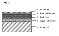
- a gravure plate-making roll of the present invention includes a metal hollow roll, a copper plating layer with a number of gravure cells formed on a surface thereof, provided on a surface of the hollow roll, a metal layer provided on a surface of the copper plating layer, a metal carbide layer of the metal provided on a surface of the metal layer, and a diamond-like coating covering a surface of the metal carbide layer.
- a method of producing a gravure plate-making roll of the present invention includes a process of preparing a metal hollow roll, a copper plating process of forming a copper plating layer on a surface of the hollow roll, a gravure cell formation process of forming a number of gravure cells on a surface of the copper plating layer, a metal layer formation process of forming a metal layer on a surface of the copper plating layer, a metal carbide layer formation process of forming a metal carbide layer of the metal on a surface of the metal layer, and a diamond-like carbon coating formation process of forming a diamond-like carbon coating on a surface of the metal carbide layer.
- the metal carbide layer is preferably a metal carbide inclined layer, and a composition ratio of carbon in the metal carbide inclined layer is set so that a proportion of carbon increases gradually in a direction of the diamond-like carbon coating from the metal layer side.
- a thickness of the copper plating layer is 50 to 200 ⁇ m, a depth of the gravure cells is 5 to 150 ⁇ m, a thickness of the metal layer is 0.1 to 1 ⁇ m, a thickness of the metal carbide layer is 0.1 to 1 ⁇ m, and a thickness of the diamond-like carbon coating is 0.1 to 10 ⁇ m.
- the metal layer, the metal carbide layer, preferably, a metal carbide inclined layer, and the diamond-like carbon coating each be formed by sputtering.
- the metal it is preferable to use a metal capable of being carbonated and having high compatibility with copper.
- the metal is one or at least two kinds of metals selected from the group consisting of tungsten (W), silicon (Si), titanium (Ti), chromium (Cr), tantalum (Ta), and zirconium (Zr).
- W tungsten
- Si silicon
- Ti titanium
- Cr chromium
- Ta tantalum
- Zr zirconium
- the gravure cells may be formed by etching or electronic engraving, and etching is preferable.
- the etching is a method of coating a plate body surface of a gravure cylinder with a sensitizing solution to perform direct burning, followed by etching, thereby forming gravure cells.
- the electronic engraving is a method of mechanically operating a diamond engraving needle in accordance with a digital signal to engrave gravure cells on the copper surface of the gravure cylinder.
- a chromium plating process can be omitted by using a diamond-like carbon (DLC) coating as a surface-reinforcing coating layer. Therefore, great effects can be exhibited in which it is not necessary to use hexavalent chromium with high toxicity, an excess cost for keeping the safety of an operation is not necessary, there is no possibility of the occurrence of pollution, and furthermore, and a diamond-like carbon (DLC) coating has strength comparable to that of a chromium layer and is excellent in printing durability.
- DLC diamond-like carbon
- 10 a plate base metal (a hollow roll), 10a: a gravure plate-making roll, 12: a copper plating layer, 14: a gravure cell, 16: a metal layer, 18: a metal carbide layer, preferably, a metal carbide inclined layer, 20: a diamond-like carbon (DLC) coating
- 10a a plate base metal (a hollow roll)
- 10a a gravure plate-making roll
- 12 a copper plating layer
- 14 a gravure cell
- 16 a metal layer
- 18 a metal carbide layer, preferably, a metal carbide inclined layer
- 20 a diamond-like carbon (DLC) coating
- FIG. 1 is an explanatory diagram schematically illustrating a production process of a gravure plate-making roll of the present invention: (a) is an entire cross-sectional view of a hollow roll; (b) is a partial enlarged cross-sectional view illustrating a state in which a copper plating layer is formed on the surface of the hollow roll; (c) is a partial enlarged cross-sectional view illustrating a state in which gravure cells are formed on the copper plating layer of the hollow roll; (d) is a partial enlarged cross-sectional view illustrating a state in which a metal layer is formed on the surface of the copper plating layer of the hollow roll; (e) is a partial enlarged cross-sectional view illustrating a state in which a metal carbide layer is formed on the surface of the metal layer of the hollow roll; and (f) is a partial enlarged cross-sectional view illustrating a state in which a diamond-like carbon (DLC) coating covers the surface of the metal carbide layer of the hollow roll.
- reference numeral 10 denotes a plate base metal, and a metal hollow roll made of aluminum or iron is used for the plate base metal (Step 100 of FIG. 2 ).
- a copper plating layer 12 is formed on the surface of the hollow roll 10 by copper plating (Step 102 of FIG. 2 ).
- a number of minute concave portions (gravure cells) 14 are formed (Step 104 of FIG. 2 ).
- a known method can be used, such as etching (coating a plate body surface with a sensitizing solution to perform direct burning, followed by etching, thereby forming the gravure cells 14) or electronic engraving (mechanically operating a diamond engraving needle with a digital signal to engrave the gravure cells 14 on the surface of copper), and etching is preferable.
- a metal layer 16 is formed (Step 106 of FIG. 2 ). Furthermore, a metal carbide layer of the metal, preferably, a metal carbide inclined layer 18 is formed on the surface of the metal layer 16 (Step 108 of FIG. 2 ).
- known methods such as sputtering, vapor deposition (electron beam method), ion plating, molecular beam epitaxy (MBE), laser abrasion, ion assist film-formation, or plasma CVD can be applied, and sputtering is preferable.
- the metal a metal capable of being carbonated and having high compatibility with copper is preferable.
- the metal it is possible to use tungsten (W), silicon (Si), titanium (Ti), chromium (Cr), tantalum (Ta), and zirconium (Zr).
- the metal in the metal carbide layer preferably, the metal carbide inclined layer 18, the same metal as that of the metal layer 16 is used.
- the composition ratio of carbon in the metal carbide inclined layer 18 is set so that the proportion of carbon increases gradually from the metal layer 16 side in the direction of a diamond-like carbon (DLC) coating 20 described later. That is, film formation is performed so that the composition ratio of carbon increases gradually in a proportion from 0% (in stages or in non-stages) to finally reach about 100%.
- DLC diamond-like carbon
- the metal carbide inclined layer 18 As a method of adjusting the composition ratio of carbon in the metal carbide layer, preferably, the metal carbide inclined layer 18, a known method may be used.
- the metal carbide layer i.e., the metal carbide inclined layer 18
- the composition ratios of carbon and metal are changed so that the proportion of carbon in the metal carbide layer 18 increases gradually in stages or in non-stages in the direction of the diamond-like carbon (DLC) coating 20 from the copper plating layer 12 side, for example, by sputtering (the injection amount of hydrocarbon gas such as methane gas, ethane gas, propane gas, butane gas, or acetylene gas increases gradually in stages or in non-stages in an argon gas atmosphere, using a solid metal target).
- DLC diamond-like carbon
- the contact of the metal carbide layer 18 with respect to both the copper plating layer 12 and the diamond-like carbon (DLC) coating 20 can be enhanced. Furthermore, if the injection amount of hydrocarbon gas is set to be constant, a metal carbide layer in which the composition ratios of carbon and metal are set to be constant can be formed, and the metal carbide layer thus obtained is allowed to function similarly to that of the metal carbide inclined layer.
- the diamond-like carbon (DLC) coating 20 is formed so as to cover the surface of the metal carbide layer (Step 110 of FIG. 2 ).
- a known method such as sputtering, vacuum deposition (electron beam method), ion plating, molecular beam epitaxy (MBE), laser abrasion, ion assist film formation, or plasma CVD can be applied, and sputtering is preferable.
- the above-mentioned diamond-like carbon (DLC) coating 20 is covered, and is allowed to function as a surface-reinforcing coating layer, whereby a gravure plate-making roll 10a excellent in printing durability without toxicity and any possibility of the occurrence of pollution can be obtained.
- DLC diamond-like carbon
- ions are allowed to strike a material (target material) desired to be a thin film, the material is sputtered, and the sputtered material is deposited on a substrate to produce a thin film.
- Sputtering is characterized in that there is no particular constraint to a target material, and a thin film can be produced with good reproducibility in a large area, etc.
- Vacuum deposition a material desired to be a thin film is heated to be evaporated by the irradiation of electron beams, and the evaporated material adheres (is deposited) on a substrate to produce a thin film.
- Vacuum deposition is characterized in that a film formation speed is high, and the damage to a substrate is small, etc.
- a material desired to be a thin film is evaporated and ionized with a radio frequency (RF) (RF ion plating) or arc (arc ion plating), and deposited on a substrate to produce a thin film.
- RF radio frequency
- arc arc ion plating
- the ion plating is characterized in that a film formation speed is high, and adhesion strength is large, etc.
- the molecular epitaxy is a method of evaporating a raw material in an ultrasonic vacuum, and supplying the raw material to a heated substrate to form a thin film.
- the laser abrasion is a method of allowing a laser pulse increased in density to be incident upon a target to allow ions to be released, thereby forming a thin film on an opposed substrate.
- the ion assist film formation is a method of setting an evaporation source and an ion source in a vacuum container, and forming a film, using ions, supplementarily.
- the plasma CVD is a method of decomposing a material gas using the excitation of plasma, and allowing the material gas to be deposited by reaction on a substrate, for the purpose of forming a thin film at a temperature lower than that for CVD under a reduced pressure.
- a gravure cylinder (aluminum hollow roll) with a circumference of 600 mm and a roll length of 1100 mm was placed in a plating bath.
- An anode chamber was brought close to the hollow roll up to 20 mm by an automatic slide apparatus under a computer system to allow a plating solution to overflow to immerse the hollow roll completely, whereby a copper plating layer of 80 ⁇ m was formed at 18 A/dm 2 and 6.0 V.
- a plating time was 20 minutes, and no rashes and pits were generated on the surface of plating. Thus, a uniform copper plating layer was obtained.
- the copper plating layer thus formed was coated with a photosensitive film. An image was exposed to a laser to be developed, followed by burning, thereby forming a resist image. Then, dry etching such as plasma etching was conducted to engrave an image made of gravure cells. After that, a resist image was removed to form a printing plate. At this time, three hollow rolls with a gravure cell depth of 10 ⁇ m (Example 1), 18 ⁇ m (Example 2), and 30 ⁇ m (Example 3) were produced.
- a tungsten (W) layer was formed by sputtering.
- the sputtering conditions were as follows.
- a tungsten (W) sample a solid tungsten target, an atmosphere: an argon gas environment, a film formation temperature: 200°C to 300°C, a film formation time: 60 minutes, and a film formation thickness: 0.1 ⁇ m.
- tungsten carbide layer was formed on the upper surface of the tungsten layer (W).
- the sputtering conditions were as follows.
- a diamond-like carbon (DLC) coating was formed so as to cover the upper surface of the tungsten carbide by sputtering.
- the sputtering conditions were as follows.
- a DLC sample a solid carbon target, an environment: an argon gas environment, a film formation temperature: 200°C to 300°C, a film formation time: 150 minutes, and a film formation thickness: 1 ⁇ m.
- a gravure plate-making roll gravure cylinder
- Example 4 Three hollow rolls were produced in which the gravure cell depth was 10 ⁇ m (Example 4), 18 ⁇ m (Example 5), and 30 ⁇ m (Example 6) in the same way as in Examples 1-3.
- the three hollow rolls were treated to complete gravure plate-making rolls in the same way as in Examples 1-3 except that a tungsten (W) sample was changed to a silicon (Si) sample, and a printing test was conducted similarly. Consequently, printed matters without plate fogging, having satisfactory transferability, were obtained similarly. Even in these examples, it was confirmed that a diamond-like carbon (DLC) coating had performance comparable to that of a conventional chromium layer, and can be used sufficiently in place of a chromium layer.
- DLC diamond-like carbon
Landscapes
- Engineering & Computer Science (AREA)
- Manufacturing & Machinery (AREA)
- Manufacture Or Reproduction Of Printing Formes (AREA)
- Printing Plates And Materials Therefor (AREA)
Applications Claiming Priority (3)
| Application Number | Priority Date | Filing Date | Title |
|---|---|---|---|
| JP2005166067 | 2005-06-06 | ||
| JP2005288234 | 2005-09-30 | ||
| PCT/JP2006/310302 WO2006132085A1 (fr) | 2005-06-06 | 2006-05-24 | Cylindre à graver pour héliogravure et son procédé de production |
Publications (1)
| Publication Number | Publication Date |
|---|---|
| EP1889730A1 true EP1889730A1 (fr) | 2008-02-20 |
Family
ID=37498288
Family Applications (1)
| Application Number | Title | Priority Date | Filing Date |
|---|---|---|---|
| EP06756508A Withdrawn EP1889730A1 (fr) | 2005-06-06 | 2006-05-24 | Cylindre à graver pour héliogravure et son procédé de production |
Country Status (4)
| Country | Link |
|---|---|
| US (1) | US20090075116A1 (fr) |
| EP (1) | EP1889730A1 (fr) |
| KR (1) | KR20080006586A (fr) |
| WO (1) | WO2006132085A1 (fr) |
Families Citing this family (6)
| Publication number | Priority date | Publication date | Assignee | Title |
|---|---|---|---|---|
| US20090266254A1 (en) * | 2005-10-14 | 2009-10-29 | Think Laboratory Co., Ltd. | Gravure printing roll and method of manufacturing the same |
| JP5143128B2 (ja) * | 2007-04-03 | 2013-02-13 | 株式会社シンク・ラボラトリー | グラビア製版ロール及びその製造方法 |
| GR1007354B (el) * | 2009-12-15 | 2011-07-20 | Icr Ιωαννου Αβεε, | Κατασκευη κυλινδρου βαθυτυπιας με βαση απο αλουμινιο |
| CN103568470A (zh) * | 2013-10-21 | 2014-02-12 | 安徽华印机电股份有限公司 | 一种凹印版辊的制备工艺 |
| CN106891606A (zh) * | 2017-03-07 | 2017-06-27 | 龙游运申制版有限公司 | 一种版辊用无网加工工艺 |
| CN118318317A (zh) * | 2021-11-04 | 2024-07-09 | 麦修斯国际有限责任公司 | 在用于制造电极的干法涂布工艺中应用的辊 |
Family Cites Families (13)
| Publication number | Priority date | Publication date | Assignee | Title |
|---|---|---|---|---|
| US4537127A (en) * | 1984-09-12 | 1985-08-27 | Rockwell International Corporation | Black oxide lithographic ink metering roller |
| JP2635046B2 (ja) * | 1987-05-27 | 1997-07-30 | 株式会社 東京機械製作所 | 平版印刷機のインキ装置用ローラーおよび平版印刷機のインキ装置用ローラーの製造方法 |
| US4862799A (en) * | 1987-11-13 | 1989-09-05 | Rockwell International Corporation | Copper coated anodized aluminum ink metering roller |
| JPH0726380A (ja) * | 1993-07-12 | 1995-01-27 | Daikin Ind Ltd | ダイヤモンド状炭素薄膜成形体及びその製造方法 |
| US5755033A (en) * | 1993-07-20 | 1998-05-26 | Maschinenfabrik Koppern Gmbh & Co. Kg | Method of making a crushing roll |
| DE4431563A1 (de) * | 1994-09-05 | 1996-03-07 | Kloeckner Humboldt Deutz Ag | Verschleißfeste Oberflächenpanzerung für die Walzen von Hochdruck-Walzenpressen zur Druckzerkleinerung körnigen Gutes (Unterlagen zu P 44 44 337.4 gegeben) |
| DE19515394C1 (de) * | 1995-04-26 | 1996-05-23 | Roland Man Druckmasch | Verfahren zur Herstellung einer Oberflächenstruktur und dessen Anwendung, vorzugsweise für einen Druckmaschinenzylinder |
| JP2003214444A (ja) * | 2002-01-22 | 2003-07-30 | Nsk Ltd | 転がり摺動部材および転動装置 |
| JP2004130718A (ja) * | 2002-10-11 | 2004-04-30 | Nikka Kk | 版胴および輪転印刷機 |
| JP2004339564A (ja) * | 2003-05-15 | 2004-12-02 | Toyota Motor Corp | 摺動部材および皮膜形成方法 |
| US20100064918A1 (en) * | 2005-09-30 | 2010-03-18 | Think Laboratory Co., Ltd. | Gravure printing roll with cushion layer and method of producing the same |
| KR20080039937A (ko) * | 2005-09-30 | 2008-05-07 | 가부시키가이샤 씽크. 라보라토리 | 그라비아제판 롤 및 그의 제조방법 |
| US20090266254A1 (en) * | 2005-10-14 | 2009-10-29 | Think Laboratory Co., Ltd. | Gravure printing roll and method of manufacturing the same |
-
2006
- 2006-05-24 KR KR1020077025801A patent/KR20080006586A/ko not_active Ceased
- 2006-05-24 WO PCT/JP2006/310302 patent/WO2006132085A1/fr not_active Ceased
- 2006-05-24 EP EP06756508A patent/EP1889730A1/fr not_active Withdrawn
- 2006-05-24 US US11/914,450 patent/US20090075116A1/en not_active Abandoned
Non-Patent Citations (1)
| Title |
|---|
| See references of WO2006132085A1 * |
Also Published As
| Publication number | Publication date |
|---|---|
| WO2006132085A1 (fr) | 2006-12-14 |
| KR20080006586A (ko) | 2008-01-16 |
| US20090075116A1 (en) | 2009-03-19 |
Similar Documents
| Publication | Publication Date | Title |
|---|---|---|
| JP5015991B2 (ja) | 印刷用ロールおよびその製造方法 | |
| JPWO2007135901A1 (ja) | グラビア製版ロール及びその製造方法 | |
| EP1938970A1 (fr) | Rouleau a graver pour photogravure et procede de production de celui-ci | |
| JP2004130718A (ja) | 版胴および輪転印刷機 | |
| JPWO2007135898A1 (ja) | グラビア製版ロールの全自動製造システム | |
| EP1946938A1 (fr) | Rouleau pour impression par gravure et son procédé de fabrication | |
| US20090075116A1 (en) | Gravure plate-making roll and method of producing the same | |
| US10737522B2 (en) | Process for producing a printing surface | |
| EP1930173A1 (fr) | Rouleau a graver pour photogravure avec couche d'amortissement et procede de production associe | |
| US20180093467A1 (en) | Gravure cylinder and manufacturing method thereof | |
| JP2007130996A (ja) | グラビア製版ロール及びその製造方法 | |
| JP5143128B2 (ja) | グラビア製版ロール及びその製造方法 | |
| CN101184630A (zh) | 凹版制版辊及其制造方法 | |
| JPWO2007135900A1 (ja) | グラビア製版ロール及びその製造方法 | |
| JP2007118594A (ja) | グラビア製版ロール及びその製造方法 | |
| JPH05221171A (ja) | グラビア印刷シリンダー製造用金属プレート、該金属プレートの製造方法、及び図柄を造形されたロール | |
| JPWO2007132734A1 (ja) | グラビア製版ロール及びその製造方法 | |
| JPWO2006132085A1 (ja) | グラビア製版ロール及びその製造方法 | |
| JP2007118593A (ja) | クッション層付グラビア製版ロール及びその製造方法 | |
| WO1991013762A1 (fr) | Rouleau d'impression a trames comportant une couche superieure a dessin realisee par depôt electrolytique, et un corps de rouleau pour ledit rouleau | |
| EP3672806A1 (fr) | Corps d'impression | |
| EP1188577B1 (fr) | Procédé et appareil pour la fabrication de cylindres de gravure | |
| JPWO2008038716A1 (ja) | 積層軟包装材料及びその製造方法 | |
| JPWO2008059705A1 (ja) | グラビア製版ロール及びその製造方法 | |
| JPH11309950A (ja) | グラビア印刷版、及び、グラビア印刷版の製造方法 |
Legal Events
| Date | Code | Title | Description |
|---|---|---|---|
| PUAI | Public reference made under article 153(3) epc to a published international application that has entered the european phase |
Free format text: ORIGINAL CODE: 0009012 |
|
| 17P | Request for examination filed |
Effective date: 20071205 |
|
| AK | Designated contracting states |
Kind code of ref document: A1 Designated state(s): AT CH DE GB IT LI |
|
| RBV | Designated contracting states (corrected) |
Designated state(s): AT CH DE GB IT LI |
|
| DAX | Request for extension of the european patent (deleted) | ||
| RBV | Designated contracting states (corrected) |
Designated state(s): AT CH DE GB IT LI |
|
| STAA | Information on the status of an ep patent application or granted ep patent |
Free format text: STATUS: THE APPLICATION HAS BEEN WITHDRAWN |
|
| 18W | Application withdrawn |
Effective date: 20090220 |