EP1889804A2 - Dispositif d'enroulement de rouleaux destiné à l'enroulement d'une bande de matériau - Google Patents
Dispositif d'enroulement de rouleaux destiné à l'enroulement d'une bande de matériau Download PDFInfo
- Publication number
- EP1889804A2 EP1889804A2 EP07113318A EP07113318A EP1889804A2 EP 1889804 A2 EP1889804 A2 EP 1889804A2 EP 07113318 A EP07113318 A EP 07113318A EP 07113318 A EP07113318 A EP 07113318A EP 1889804 A2 EP1889804 A2 EP 1889804A2
- Authority
- EP
- European Patent Office
- Prior art keywords
- roll
- winding device
- roller
- web
- winding
- Prior art date
- Legal status (The legal status is an assumption and is not a legal conclusion. Google has not performed a legal analysis and makes no representation as to the accuracy of the status listed.)
- Withdrawn
Links
Images

Classifications
-
- B—PERFORMING OPERATIONS; TRANSPORTING
- B65—CONVEYING; PACKING; STORING; HANDLING THIN OR FILAMENTARY MATERIAL
- B65H—HANDLING THIN OR FILAMENTARY MATERIAL, e.g. SHEETS, WEBS, CABLES
- B65H19/00—Changing the web roll
- B65H19/22—Changing the web roll in winding mechanisms or in connection with winding operations
- B65H19/2238—The web roll being driven by a winding mechanism of the nip or tangential drive type
- B65H19/2246—The web roll being driven by a winding mechanism of the nip or tangential drive type and the roll being supported on two rollers
-
- B—PERFORMING OPERATIONS; TRANSPORTING
- B65—CONVEYING; PACKING; STORING; HANDLING THIN OR FILAMENTARY MATERIAL
- B65H—HANDLING THIN OR FILAMENTARY MATERIAL, e.g. SHEETS, WEBS, CABLES
- B65H19/00—Changing the web roll
- B65H19/22—Changing the web roll in winding mechanisms or in connection with winding operations
- B65H19/26—Cutting-off the web running to the wound web roll
- B65H19/265—Cutting-off the web running to the wound web roll using a cutting member moving linearly in a plane parallel to the surface of the web and along a direction crossing the web
-
- B—PERFORMING OPERATIONS; TRANSPORTING
- B65—CONVEYING; PACKING; STORING; HANDLING THIN OR FILAMENTARY MATERIAL
- B65H—HANDLING THIN OR FILAMENTARY MATERIAL, e.g. SHEETS, WEBS, CABLES
- B65H2301/00—Handling processes for sheets or webs
- B65H2301/40—Type of handling process
- B65H2301/41—Winding, unwinding
- B65H2301/414—Winding
- B65H2301/4148—Winding slitting
-
- B—PERFORMING OPERATIONS; TRANSPORTING
- B65—CONVEYING; PACKING; STORING; HANDLING THIN OR FILAMENTARY MATERIAL
- B65H—HANDLING THIN OR FILAMENTARY MATERIAL, e.g. SHEETS, WEBS, CABLES
- B65H2301/00—Handling processes for sheets or webs
- B65H2301/40—Type of handling process
- B65H2301/41—Winding, unwinding
- B65H2301/417—Handling or changing web rolls
- B65H2301/4187—Relative movement of core or web roll in respect of mandrel
- B65H2301/4189—Cutting
- B65H2301/41892—Cutting knife located in winding or guiding roller and protruding therefrom
-
- B—PERFORMING OPERATIONS; TRANSPORTING
- B65—CONVEYING; PACKING; STORING; HANDLING THIN OR FILAMENTARY MATERIAL
- B65H—HANDLING THIN OR FILAMENTARY MATERIAL, e.g. SHEETS, WEBS, CABLES
- B65H2406/00—Means using fluid
- B65H2406/30—Suction means
- B65H2406/33—Rotary suction means, e.g. roller, cylinder or drum
Definitions
- the invention relates to a roll winding device for winding a material web, in particular a paper or board web, on at least one winding tube to at least one winding roll, which is mounted in a winding bed formed by a first and a second axially parallel support roller, wherein the material web over a partial peripheral surface of the first Support roller runs, the roll shell is provided with recesses open against its peripheral surface, and wherein an at least temporarily activatable separation device for web-wide separation of the material web in the region of the partial peripheral surface is provided when producing a new material web start.
- a material web for example in the form of a paper or board web, is produced in a relatively large width of currently up to 12 m and virtually endless.
- the material web In order to be usable for a later consumer, for example a printing company, the material web must be subdivided into narrower webs, so-called material part webs. These narrower webs of material must then be wound into bobbins. For this purpose, a roll winder is used.
- the invention is also applicable to other webs, which also have to be wound into bobbins and handled in a similar manner, such as sheets of cardboard, plastic or metal foil, respectively.
- the material web running over a partial circumferential surface of the support roll is moved by means of a traversing separating knife on the Peripheral surface of the support or support roller separated by machine.
- the support roller is usually provided with recesses open against its circumferential surface, so-called air discharge grooves. These recesses prevent, especially at high grammages, a safe separation of the web. For example, stay at grooved places like bars.
- the material web is held during its separation by means of negative pressure on the peripheral surface of the support roller to thereby reliably supply the material web start the winding tube set for the next roll set to be wound up.
- the negative pressure for the carrier roll punched across its entire roll shell is generated by means of a vacuum fan.
- the achievable negative pressure is reduced such that grammages ⁇ 150 g / m 2 are no longer securely held.
- an excess of false air is caused by causing increased operating costs in the vacuum system.
- the use of a suction zone integrated in the carrier roll is also provided.
- the suction box forming the suction and arranged in the interior of the support roller suction box requires a complex supply and control / regulation system.
- various balancing measures have to be taken so that the reel winders can still be operated efficiently and safely even at higher machine speeds.
- the separating surface viewed in the circumferential direction of the first carrier roll, has a length in the range of 10 to 25 mm, preferably 15 to 20 mm. This length allows an ideal separation of the material web due to the present surface even if the first support roller is not positioned correctly, be it in the forerun or in the caster. In addition, as a result of this length, the material web to be separated sufficiently flat and thus also safely supported.
- the first support roller may be formed as a steel roller. In addition, it can also have an elastomeric cover. In both cases, it may also be provided with recesses open against its peripheral surface.
- the recesses in the area of the continuous web-width parting surface are preferably designed to be discontinuous at least on the feed side. In a further embodiment, they can also be designed to drain on the outlet side. These measures ensure that no air blasts or even air turbulences are generated during normal operation of the reel winder due to suddenly changing contours with air guidance. Overall, the material web can be performed better and quieter over the partial circumferential surface of the first support roller.
- the recesses in the run-up side region of the continuous web-width separating surface can also be acted upon at least in some areas by suction means forming a suction zone. This allows, on the one hand, a fast system evacuation due to a small volume at a sufficiently high volume flow, on the other hand, a sufficiently high pressure for safe supply of the material web start to the core set for the next roll set to be wound up.
- the suction means preferably comprise at least one continuous and axially parallel suction hole in the roll shell, which are connected to preferably radially arranged suction channels, which in turn preferably penetrate the peripheral surface of the first support roller in the region of the recesses.
- suction channels preferably penetrate the peripheral surface of the first support roller in the region of the recesses.
- the suction means further comprise at least one preferably controllable / controllable Suction source, preferably a controllable / controllable vacuum source.
- a controllable / controllable vacuum source preferably a controllable / controllable vacuum source. This can be arranged on the outside, that is, the front side and stationary of the first support roller and can be connected as needed with the other suction means.
- the roll shell is provided on the inside of the at least one continuous and axially parallel suction bore in an ideal manner with at least one balance weight.
- the at least temporarily activatable separating device has, in a preferred embodiment, at least one web-width traversing separating knife. This type of separation is on the one hand, even with material webs with high grammages process reliability, on the other hand, the use of a separating knife as a separating element is inexpensive.
- At least one device for applying at least one adhesive strip to the new material web beginning can additionally be provided.
- This second transfer medium after a successful separation of the material web, further improves the process reliability for transferring the new material web beginning to the winding tube set for the next roll set to be wound up.
- the device for applying at least one adhesive strip to the new material web beginning can be connected to a device for pushing out the wound winding roller from the roller bed to form a unit. This provides the advantage of as few moving components with corresponding movement units.
- At least one blower device acting at least regionally, preferably with a web width can be provided for blowing the new material web start onto the winding tube to be wound be, whereby the process reliability for the transfer of the new material web start to the winding tube set for the next roll-up set to be further improved.
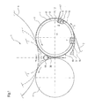
- the roll winding device 1 accordingly has a first axially parallel support roll 3 and a second axially parallel support roll 4, which form a winding bed 5 between them, in which an indicated winding roll 6 is arranged.
- the indicated winding roller 6 is shown here with diameters of different sizes in order to make the progress, ie the diameter increase, visible during winding.
- a supply station from which the material web 2 is withdrawn.
- This element is known per se in a roll winder.
- a plurality of winding rolls 6 can be arranged axially one behind the other in the winding bed 5 in the axial direction of the two support rolls 3, 4.
- the individual bobbins 6 are expediently distributed on both sides of the corresponding roller.
- such a roll winding device 1 is also provided with a longitudinal cutting device which divides the tapered material web 2 into a plurality of partial webs running parallel to one another.
- the partial webs may have a width in the range of about 0.3 to 4.8 m.
- a reel winder such as a back-up roll, also referred to as a rider or load roll, or drive motors for the support rolls 3, 4 are not shown.
- the material web 2 passes over a partial circumferential surface 7 of the first support roller 3, the roll shell 8 has an elastomeric cover 9 and is provided with open towards its peripheral surface 10 recesses 11.
- the recesses 11 are designed as substantially in the circumferential direction R (arrow) of the support roller 3 extending Lucasab thoroughlynuten 12.
- the slitter-winder 1 further has a suction zone 13 integrated in the support roller 3, which is temporarily generated by a suction box 15 arranged in the inner region 14 of the support roller 3.
- a machine-wide cutting support 16 is introduced between the peripheral surface 10 of the support roll 3 and the material web 2 to be separated (position 1). If the introduced cutting pad 16 reaches a certain circumferential position (position II), then the over the partial circumferential surface 7 of the support roller 3 is running Material web 2 by means of an at least temporarily activatable, that is traversing cutting blade 17 on the partial circumferential surface 7 of the support roller 3 when producing a new material web start 18 machine width separated.
- the new material web start 18 can be supplied in a known manner the winding tube set for the next roll set to be wound up, represented by the new winding tube 19.
- the introduced cutting pad 16 must finally be selectively detected again in a merely indicated tray 37.
- FIGS. 2 to 5 show various schematic details of an embodiment of a roll winding device 1 according to the invention.
- this roll winding device 1 corresponds in essential parts to the embodiment of the roll winding device 1 shown and described in FIG. 1, so that reference is made to this.
- FIG. 3 The difference from the embodiment of FIG. 1, which represents the prior art, according to the schematic partial plan view of FIG. 2, is that a continuous web-width separating surface 20 in the effective region W of the first and the winding roll arranged axially parallel to the support roller 3 at least temporarily activatable separating device 21 (see Figure 3) is provided.
- the separating device 21 comprises at least one web-width traversing separating knife 22, which is indicated only symbolically (cf., again, FIG. 3).
- the separation surface 20 has - seen in the circumferential direction R (arrow) of the first support roller 3 - a length L in the range of 10 to 25 mm, preferably from 15 to 20 mm.
- the first support roller 3 has, as shown in the schematic sectional view of Figure 3 according to the section line AA of Figure 2, a steel core 24 and the roll shell 8 forming elastomer cover 9, which is provided with open towards its peripheral surface 10 recesses 11.
- the recesses 11 are designed as grooves 25 and in the circumferential direction R (arrow) the first support roller 3 running inclined (see Figure 2).
- the recesses 11 can also be embodied as blind bores and / or running essentially in the circumferential direction R (arrow) of the first support roller 3.
- the first support roller 3 may be formed as a steel roller with corresponding recesses 11.
- the recesses 11 in the form of mutually parallel grooves 25 are in the region of the continuous web-width separating surface 20 both run-up side (arrow B) and the inlet side (arrow C) running expiring.
- the recesses 11 in the form of mutually parallel grooves 25 in the inlet side region (arrow B) of the continuous web-width separating surface 20 at least partially applied to a suction zone 27 forming suction means 26.
- the suction means 26 comprise in the embodiment shown, three continuous and axially parallel suction holes 28 in the roll shell 8, which are each connected to a radially arranged suction channel 29 (see Figure 4).
- the suction channels 29 in turn penetrate the peripheral surface 10 of the first support roller 3 in the region of the recesses 11.
- the suction means 26 further comprise at least one preferably controllable / controllable suction source 30, preferably a controllable / controllable vacuum source 31, which is not explicitly shown, the expert however, it is known.
- Figure 4 shows a schematic sectional view of the first support roller 3 in the region of the suction means 26.
- the suction means 26 with its three continuous and axially parallel suction holes 28 in the roll shell 8 are arranged such that they provide an optimal version and leadership of the not shown Contribute material web beginning. They are thus arranged upstream side (arrow B) of the mutually parallel grooves 25 of the roll shell 8.
- the roll shell 8 is on the inside of the three continuous and axially parallel suction holes 28 of the suction zone 27 with each provided a balance weight 32.
- the respective balance weight 32 is designed in terms of its geometry and mass distribution such that the missing mass of the associated suction bore 28 is compensated. Of course, the use of only one balance weight on the roll shell 8 may be provided.
- the roll winding device 1 may comprise at least one device 33, not shown, for applying at least one adhesive strip to the new material web beginning, said device 33 being connected in a favorable manner to a device 35 for ejecting the wound winding roll from the roll bed.
- a device 35 is for example in the European patent application EP 1 652 803 A2 set; Their content is hereby made the subject of the present description.
- the unit 35 together with its devices 33, 34 is indicated in FIG. 4 only in an abstract manner.
- the roll winding device 1 may have at least one blowing device 36, which acts at least regionally, preferably in web width and merely indicated, for blowing the new material web beginning 18 against the winding tube 19 to be wound.
- the blowing device 36 is arranged below the winding bed 5 of the roll winding device 1, that is to say between the two support rolls 3, 4 (cf., FIG. 1).
- a roller winding device of the type mentioned above is provided by the invention, with which a process improved, in particular temporally shortened separation of a material web, in particular also a material web can be made with a high grammage.
Landscapes
- Replacement Of Web Rolls (AREA)
- Unwinding Webs (AREA)
Applications Claiming Priority (1)
| Application Number | Priority Date | Filing Date | Title |
|---|---|---|---|
| DE200610038955 DE102006038955A1 (de) | 2006-08-18 | 2006-08-18 | Rollenwickelvorrichtung zum Aufwickeln einer Materialbahn |
Publications (2)
| Publication Number | Publication Date |
|---|---|
| EP1889804A2 true EP1889804A2 (fr) | 2008-02-20 |
| EP1889804A3 EP1889804A3 (fr) | 2011-11-16 |
Family
ID=38736006
Family Applications (1)
| Application Number | Title | Priority Date | Filing Date |
|---|---|---|---|
| EP07113318A Withdrawn EP1889804A3 (fr) | 2006-08-18 | 2007-07-27 | Dispositif d'enroulement de rouleaux destiné à l'enroulement d'une bande de matériau |
Country Status (2)
| Country | Link |
|---|---|
| EP (1) | EP1889804A3 (fr) |
| DE (1) | DE102006038955A1 (fr) |
Family Cites Families (4)
| Publication number | Priority date | Publication date | Assignee | Title |
|---|---|---|---|---|
| DE2920707C2 (de) * | 1979-05-22 | 1990-05-31 | Jagenberg-Werke AG, 4000 Düsseldorf | Verfahren und Doppeltragwalzen-Wickelmaschine zum automatischen Trennen und Anwickeln einer Warenbahn |
| DE19505870C2 (de) * | 1995-02-21 | 2000-01-13 | Voith Sulzer Papiermasch Gmbh | Vorrichtung zum Auf- bzw. Abwickeln von bahnförmigem Gut, insbesondere von Faserstoffbahnen |
| US6305635B1 (en) * | 1997-07-30 | 2001-10-23 | Windmoeller & Hoelscher Kg | Continuous web winding method and device with suction-induced winding start of empty core mandrels |
| DE19812723A1 (de) * | 1998-03-24 | 1999-09-30 | Voith Sulzer Papiertech Patent | Rollenwickelwalze |
-
2006
- 2006-08-18 DE DE200610038955 patent/DE102006038955A1/de not_active Withdrawn
-
2007
- 2007-07-27 EP EP07113318A patent/EP1889804A3/fr not_active Withdrawn
Also Published As
| Publication number | Publication date |
|---|---|
| DE102006038955A1 (de) | 2008-02-21 |
| EP1889804A3 (fr) | 2011-11-16 |
Similar Documents
| Publication | Publication Date | Title |
|---|---|---|
| DE60105027T2 (de) | Wickelwelle und wickler zum wickeln einer papierbahn | |
| DE2935743A1 (de) | Zusatzvorrichtung an aufrolleinrichtungen und verfahren zum aufrollen von druckempfindlichen materialbahnen | |
| EP0792829A2 (fr) | Procédé et dispositif pour enrouler une bande de papier en un rouleau | |
| EP1106554A2 (fr) | Plieuse mobile et arrangement de triangle plieur | |
| EP0744365B1 (fr) | Méthode pour changer le rouleau dans une machine à enrouler et machine à enrouler pour l'application de cette méthode | |
| EP1999051B1 (fr) | Dispositifs et procédé d'acheminement une bande de matière à une unité d'impression d'une rotative d'imprimerie | |
| DE102010027820A1 (de) | Verfahren und Vorrichtung zum Einfädeln einer Faserstoffbahn in einem Aufwickler | |
| DE102016225980A1 (de) | Vorrichtung zum Abschneiden einer an einer durch die Vorrichtung zu führenden Materialbahn hängenden Materialbahnfahne, Rollendruckmaschine sowie Verfahren zum Herstellen eines Produktes mit einer Rollendruckmaschine | |
| DE4409036A1 (de) | Verfahren und Wickelmaschine zum Aufwickeln einer Materialbahn, insbesondere einer Papier- oder Kartonbahn | |
| EP1179630B1 (fr) | Procédé et dispositif pour la production de rouleaux de papier | |
| EP1889804A2 (fr) | Dispositif d'enroulement de rouleaux destiné à l'enroulement d'une bande de matériau | |
| EP1038817A2 (fr) | Méthode et dispositif pour guider une bande de matériau sur un tambour | |
| DE102010044203B4 (de) | Verfahren zum Längsschneiden einer Faserbahn | |
| EP1657194B1 (fr) | Dispositif d'enroulage de bobines et procédé pour l'enroulement de bobines | |
| EP1897831A2 (fr) | Procédé destiné au changement de rouleau dans un dispositif d'enroulement de rouleaux et dispositif d'enroulement de rouleaux pour l'enroulement d'une bande de matériau | |
| EP4077804B1 (fr) | Dispositif et procédé de transfert d'une nappe de matière fibreuse | |
| EP1657193B1 (fr) | Dispositif d'enroulage de bobines et procédé pour l'enroulement de bobines | |
| EP0957054A1 (fr) | Machine et procédé pour l'enroulement d'une bande de matière | |
| EP3962848B1 (fr) | Poste de déroulement | |
| DE19720174B4 (de) | Kalander | |
| DE19755267C2 (de) | Rollenschneider und Verfahren zum Aufteilen einer Materialbahn in Teilbahnen | |
| DE102008040883A1 (de) | Wickelvorrichtung, insbesondere Stützwalzenwickelvorrichtung | |
| DE60015144T2 (de) | Verfahren zum kontinuierlichen aufwickeln von papier und wickler | |
| EP1818298A2 (fr) | Méthode et dispositif pour enrouler des bandes de parties de matériau sur des noyaux, pour former des rouleaux de partie de matériau | |
| EP2301871B1 (fr) | Procédé et dispositif de chargement de noyaux pour enrouleuse avec deux cylindres de support en fonctionnement continu |
Legal Events
| Date | Code | Title | Description |
|---|---|---|---|
| PUAI | Public reference made under article 153(3) epc to a published international application that has entered the european phase |
Free format text: ORIGINAL CODE: 0009012 |
|
| AK | Designated contracting states |
Kind code of ref document: A2 Designated state(s): AT BE BG CH CY CZ DE DK EE ES FI FR GB GR HU IE IS IT LI LT LU LV MC MT NL PL PT RO SE SI SK TR |
|
| AX | Request for extension of the european patent |
Extension state: AL BA HR MK YU |
|
| PUAL | Search report despatched |
Free format text: ORIGINAL CODE: 0009013 |
|
| AK | Designated contracting states |
Kind code of ref document: A3 Designated state(s): AT BE BG CH CY CZ DE DK EE ES FI FR GB GR HU IE IS IT LI LT LU LV MC MT NL PL PT RO SE SI SK TR |
|
| AX | Request for extension of the european patent |
Extension state: AL BA HR MK RS |
|
| RIC1 | Information provided on ipc code assigned before grant |
Ipc: B65H 19/28 20060101ALI20111013BHEP Ipc: B65H 19/30 20060101ALI20111013BHEP Ipc: B65H 19/26 20060101ALI20111013BHEP Ipc: B65H 18/20 20060101ALI20111013BHEP Ipc: B65H 18/02 20060101ALI20111013BHEP Ipc: B65H 19/22 20060101AFI20111013BHEP |
|
| AKY | No designation fees paid | ||
| REG | Reference to a national code |
Ref country code: DE Ref legal event code: R108 |
|
| REG | Reference to a national code |
Ref country code: DE Ref legal event code: R108 Effective date: 20120725 |
|
| STAA | Information on the status of an ep patent application or granted ep patent |
Free format text: STATUS: THE APPLICATION IS DEEMED TO BE WITHDRAWN |
|
| 18D | Application deemed to be withdrawn |
Effective date: 20120517 |