EP1890159A2 - Verfahren und Vorrichtung zum Erkennen einer Unterspannungsversorgung wenigstens eines Hallsensors - Google Patents
Verfahren und Vorrichtung zum Erkennen einer Unterspannungsversorgung wenigstens eines Hallsensors Download PDFInfo
- Publication number
- EP1890159A2 EP1890159A2 EP07013188A EP07013188A EP1890159A2 EP 1890159 A2 EP1890159 A2 EP 1890159A2 EP 07013188 A EP07013188 A EP 07013188A EP 07013188 A EP07013188 A EP 07013188A EP 1890159 A2 EP1890159 A2 EP 1890159A2
- Authority
- EP
- European Patent Office
- Prior art keywords
- voltage
- hall sensors
- level signal
- supply
- hall
- Prior art date
- Legal status (The legal status is an assumption and is not a legal conclusion. Google has not performed a legal analysis and makes no representation as to the accuracy of the status listed.)
- Granted
Links
- 238000000034 method Methods 0.000 title claims abstract description 7
- 238000011156 evaluation Methods 0.000 claims description 6
- 239000003990 capacitor Substances 0.000 claims description 4
- 230000001419 dependent effect Effects 0.000 abstract description 2
- 238000001514 detection method Methods 0.000 description 4
- 230000007547 defect Effects 0.000 description 2
- 230000006978 adaptation Effects 0.000 description 1
- 230000005540 biological transmission Effects 0.000 description 1
- 239000002800 charge carrier Substances 0.000 description 1
- 239000004020 conductor Substances 0.000 description 1
- 230000003111 delayed effect Effects 0.000 description 1
- 238000013461 design Methods 0.000 description 1
- 238000011161 development Methods 0.000 description 1
- 238000001914 filtration Methods 0.000 description 1
- 230000007257 malfunction Effects 0.000 description 1
- 238000012545 processing Methods 0.000 description 1
- 230000003068 static effect Effects 0.000 description 1
- 238000004804 winding Methods 0.000 description 1
Images
Classifications
-
- G—PHYSICS
- G01—MEASURING; TESTING
- G01P—MEASURING LINEAR OR ANGULAR SPEED, ACCELERATION, DECELERATION, OR SHOCK; INDICATING PRESENCE, ABSENCE, OR DIRECTION, OF MOVEMENT
- G01P3/00—Measuring linear or angular speed; Measuring differences of linear or angular speeds
- G01P3/42—Devices characterised by the use of electric or magnetic means
- G01P3/44—Devices characterised by the use of electric or magnetic means for measuring angular speed
- G01P3/48—Devices characterised by the use of electric or magnetic means for measuring angular speed by measuring frequency of generated current or voltage
- G01P3/481—Devices characterised by the use of electric or magnetic means for measuring angular speed by measuring frequency of generated current or voltage of pulse signals
- G01P3/488—Devices characterised by the use of electric or magnetic means for measuring angular speed by measuring frequency of generated current or voltage of pulse signals delivered by variable reluctance detectors
-
- G—PHYSICS
- G01—MEASURING; TESTING
- G01P—MEASURING LINEAR OR ANGULAR SPEED, ACCELERATION, DECELERATION, OR SHOCK; INDICATING PRESENCE, ABSENCE, OR DIRECTION, OF MOVEMENT
- G01P21/00—Testing or calibrating of apparatus or devices covered by the preceding groups
- G01P21/02—Testing or calibrating of apparatus or devices covered by the preceding groups of speedometers
-
- G—PHYSICS
- G01—MEASURING; TESTING
- G01P—MEASURING LINEAR OR ANGULAR SPEED, ACCELERATION, DECELERATION, OR SHOCK; INDICATING PRESENCE, ABSENCE, OR DIRECTION, OF MOVEMENT
- G01P3/00—Measuring linear or angular speed; Measuring differences of linear or angular speeds
- G01P3/42—Devices characterised by the use of electric or magnetic means
- G01P3/44—Devices characterised by the use of electric or magnetic means for measuring angular speed
- G01P3/48—Devices characterised by the use of electric or magnetic means for measuring angular speed by measuring frequency of generated current or voltage
- G01P3/481—Devices characterised by the use of electric or magnetic means for measuring angular speed by measuring frequency of generated current or voltage of pulse signals
- G01P3/487—Devices characterised by the use of electric or magnetic means for measuring angular speed by measuring frequency of generated current or voltage of pulse signals delivered by rotating magnets
Definitions
- Hall sensors whose measuring principle is based on that the charge carriers of a current-carrying conductor are deflected by a perpendicular to the trajectory magnetic field, so that a Hall voltage can be tapped at the component, are usually used for speed and / or position detection of moving components.
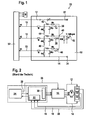
- FIG. 1 A typical application, in which Hall sensors are used both for control and for rotational speed or rotational position detection of an electronically commutated electric motor, is shown in FIG.
- Three phases of a three-phase working, electronically commutated electric motor M are controlled by an electronic control unit 10.
- the control electronics supplies via voltage supply lines 12 and 14 the power supply for Hall sensors H1, H2 and H3, via which the rotational position of the rotor of the electric motor M are detected.
- Output signals of the Hall sensors H1, H2 and H3 are fed via signal lines 16, 18 and 20 to a rotational position and direction detection device 22 whose output signals are fed to a controller 24 in which of the instantaneous rotational position and direction and the rotational speed and a desired position and / or target speed and / or desired direction of rotation dependent output signals are generated, which are supplied via a PWM signal line 26 of the control electronics 10 and fed via a further line 28 of a commutator 30, in which the necessary reversals of the motor M are calculated, then the control electronics 10 whose outputs control the windings of the motor M to the polarity and signal level (pulse width modulated signal).
- the units 22, 24, 30 and 10 with the associated connection lines are, for example, in an electronic control unit for controlling the motor M and for supplying power to the Hall sensors H1, H2 and H3, which are integral parts of the motor M united.
- the output signals of the Hall sensors alternate depending on the rotational position of the rotor of the motor M between a high level and a low level, wherein the Hall sensors are arranged such that constantly at least one high-level signal is present. Constantly is not to be understood in the strict sense of the word, since the high-level signals do not have to overlap.
- the output signals of the Hall sensors are advantageously digitized by corresponding A / D converter circuits, so that they are available in digital form (0 or 1) in the device 22 for evaluation.
- a problem of the arrangement described is that, for example due to high ohmic resistances or other errors in the power supply lines 12 or 14, the supply voltage of the Hall sensors below the specified supply voltage drops, so that their output signals for evaluation are insufficient and the rotational position of the motor M no longer be recognized. Since the state of the digitalized output signals of the Hall sensors is frozen in this case, the current error case is not recognized when the frozen Hall state is a plausible state. This is illustrated by Table 1, which indicates Hall sensor conditions.
- the fourth column indicates a frozen state in the event of an error, in which the output signal of the Hall sensors H1 and H3 is at low level and the output signal of the Hall sensor H2 is high.
- This condition is a plausible condition that is not recognized as an error.
- Error states are states 0 and 7, in which all output signals are simultaneously 0 or simultaneously 1, which can not be the case if the Hall sensors and the proper supply voltage function properly.
- the invention has for its object to provide a way by which an insufficient supply voltage of the Hall sensors can be reliably detected, so that the possibility that a frozen error case is considered plausible and is not recognized as an error, is excluded.
- a solution to this problem is achieved with a method for detecting an undervoltage supply of at least one Hall sensor, which detects a Hall sensor movement of a component and alternately emits a high level and a low level signal with moving component, the height of the high level signal from the height of the supply voltage of the Hall sensor Depends on which method that the height of the high-level signal is determined and falls below a predetermined threshold value is interpreted as an under voltage supply.
- An advantageous embodiment of the method according to the invention is that the movement of the component is detected by a plurality of Hall sensors (H1, H2, H3) located at a common supply voltage whose number and arrangement is such that at least one Hall sensor constantly outputs a high level signal Height is determined, and falls below a predetermined threshold by the high level signal is interpreted as undervoltage supply.
- a plurality of Hall sensors H1, H2, H3 located at a common supply voltage whose number and arrangement is such that at least one Hall sensor constantly outputs a high level signal Height is determined, and falls below a predetermined threshold by the high level signal is interpreted as undervoltage supply.
- An inventive device for detecting an undervoltage supply of a plurality of lying at a common voltage source Hall sensors which are arranged such that they emit at its output when moving a component alternately a high level signal and a low level signal, wherein the height of the high level signal depends on the level of the supply voltage and the arrangement and number of Hall sensors is such that constantly at least one Hall sensor emits a high level signal, characterized in that the outputs of the Hall sensors parallel to each other at a Voltage measuring means are located at the input of a voltage which corresponds substantially to the highest voltage of the output signals, and that the voltage measuring means generates an error signal when their input voltage falls below a predetermined threshold.
- each Hall sensor is connected via a rectifier diode to the input of the voltage measuring device.
- a resistor and, in parallel thereto, a capacitor are arranged between the input of the voltage measuring device and each Hall sensor, and via which the input of the voltage measuring device is connected to ground.
- the basic idea underlying the invention of determining the effective supply voltage of the Hall sensor (s) by evaluating their output signals can be used for a very wide variety of applications.
- the invention is used particularly advantageously for arrangements in which the Hall sensors form the rotational state determination sensor system of an electronically commutated electric motor.
- one of the outputs of the Hall sensors with the voltage measuring device and an evaluation circuit for comparing the input voltage of the voltage measuring device with the threshold value containing circuit are arranged on a circuit board.
- the error detection security can be detected by means for measuring a.
- Supply of the Hall sensors serving output voltage can be increased.
- a total of 32 designated electronic control device includes the modules 10, 22, 24 and 30.
- the power supply of the Hall sensors H1, H2 and H3 (Fig. 2) via terminals 33 and 34 at the ends of the supply lines 12 and 14th
- the output signals of the Hall sensors H1, H2 and H3 are supplied to the signal lines 16, 18 and 20 via the terminals 36, 38 and 40.
- For filtering the signals lying on the lines 16, 18 and 20 are each a resistor and a capacitor, which are connected in parallel.
- For adaptation serves a lying in the respective signal line ohmic resistance.
- the signal lines 16, 18 and 20 are each connected via a rectifier diode 42, 44 and 46 and an ohmic resistor to a common point 48 which is connected via a consisting of a resistor and a capacitor filter circuit with a socket 50 to which a signal can be tapped, which corresponds approximately to the respective maximum signal voltage of the Hall sensors H1, H2 and H3 and which is delayed with a given by the filter circuit time constant with respect to the respective maximum output voltage and optionally decays.
- the output voltages of the Hall sensors H1, H2 and H3 are "codified".
- the voltage which can be picked off at the socket 50 is largely independent of whether the output signals from one or two Hall sensors are at a high level.
- the aim of the illustrated in Fig. 1 circuit is that the tapped off at the socket 50 voltage is as independent as possible, whether one or more output signals of the Hall sensors are at their high level, thereby creating the smallest possible signal swing.
- a supply voltage which is too low at the Hall sensors and whose height influences the height of the high-level signal can be determined as accurately as possible.
- the decay time constant must be small enough to detect a drop in supply voltage fast enough.
- the voltage applied to the socket 50 is compared in a not shown evaluation circuit with a threshold value, which is selected such that above the threshold, a perfect processing of the output signals of the Hall sensors is guaranteed.
- Typical values are for example a stroke of the "grounded" Hall voltage at the socket 50 of less than 200 mV.
- a time constant of filtered, scaled hollow voltage of about 1 msec, for example, the A / D converted signal is sampled every 2.5 msec.
- the output voltage of the electronic control device 32 lying on the supply lines 12 and 14 is measured directly in the latter, so that fault-free operation of the electronic control device 32 can be ensured. Further, it is expedient to check the logic of the output signals of the Hall sensors in the electronic control device 32, so that the static error case of Table 1 can be detected.
- Table 2 below shows different possible error states and their recognizability.
- Table 2 Error conditions Status U Hall SG U Hall level Logic Hall signal malfunction comment 1 nok nok nok SG / cabling SG can be diagnosed when motor is disconnected 2 OK OK OK - Error-free state 3 OK OK nok Wiring / Hall sensors 4 OK nok OK cabling Contact resistance in cable / plug 5 OK nok OK Wiring / Hall sensor
- U Hall SG means the voltage applied to the supply lines 12 and 14 at the output of the electronic control device 32 and measured in the electronic control device 32.
- U Hall level means the voltage which can be removed at the socket 50.
- the error conditions 1, 3 and 5 can be detected by checking the output voltage of the electronic control device 32 or checking the logic of the output signals of the Hall sensors
- the error state 4 namely an error in the cabling of the Hall sensor only about the described evaluation of Output signals of the Hall sensors can be identified by determining the voltage at the socket 50.
- the described with reference to FIG. 1 circuit can be arranged in total on a board 52, which is for example arranged directly on the motor M and contains a specified AISIG.
- Exemplary values for the proper voltage at the output of the electronic controller 32, which is directly measured back in this, are between 4.5 and 5.5 volts.
- the signal level of the grounded Hall signals at jack 50 is rated as OK if it is between 4.0 to 6.0 volts.
- the state of the three reverb signals is OK unless it is 000 or 111.
- the evaluating or comparison circuit with an adjustable threshold value used for evaluating the signal level at the socket 50 and the signal level at an excessively low signal level is an error signal can be arranged on the board 52 or in the electronic control device 32.
Landscapes
- Physics & Mathematics (AREA)
- General Physics & Mathematics (AREA)
- Measuring Instrument Details And Bridges, And Automatic Balancing Devices (AREA)
- Transmission And Conversion Of Sensor Element Output (AREA)
- Measurement Of Current Or Voltage (AREA)
- Measuring Magnetic Variables (AREA)
- Control Of Motors That Do Not Use Commutators (AREA)
- Hall/Mr Elements (AREA)
Abstract
Description
- Hallsensoren, deren Messprinzip darauf beruht, dass die Ladungsträger eines stromdurchflossenen Leiters von einem senkrecht zur Bewegungsbahn verlaufenden Magnetfeld abgelenkt werden, so dass an dem Bauteil eine Hallspannung abgegriffen werden kann, werden üblicherweise zur Drehzahl- und/oder Positionserkennung von sich bewegenden Bauteilen eingesetzt.
- Eine typische Anwendung, bei der Hallsensoren sowohl zur Steuerung als auch zur Drehzahl- bzw. Drehpositionserkennung eines elektronisch kommutierten Elektromotors eingesetzt werden, ist in Fig. 2 dargestellt.
- Drei Phasen eines dreiphasig arbeitenden, elektronisch kommutierten Elektromotors M werden von einer Steuerelektronik 10 angesteuert. Die Steuerelektronik liefert über Spannungsversorgungsieitungen 12 und 14 die Spannungsversorgung für Hallsensoren H1, H2 und H3, über die die Drehstellung des Rotors des Elektromotors M erfasst werden.
- Ausgangssignale der Hallsensoren H1, H2 und H3 werden über Signalleitungen 16, 18 und 20 einer Drehstellungs- und Drehrichtungserfassungseinrichtung 22 zugeführt, deren Ausgangssignale einem Regler 24 zugeführt werden, in dem von dem von der augenblicklichen Drehstellung und Drehrichtung sowie der Drehgeschwindigkeit und einer Sollstellung und/oder Solldrehzahl und/oder Solldrehrichtung abhängige Ausgangssignale erzeugt werden, die über eine PWM-Signalleitung 26 der Steuerelektronik 10 zugeführt werden und über eine weitere Leitung 28 einer Kommutatorstufe 30 zugeführt werden, in der die notwendigen Umpolungen des Motors M berechnet werden, die dann der Steuerelektronik 10 zugeführt werden, deren Ausgänge die Wicklungen des Motors M nach Polung und Signalhöhe (Puls Weiten Moduliertes Signal) steuern. Die Einheiten 22, 24, 30 und 10 mit den zugehörigen Verbindungsleitungen sind beispielsweise in einem elektronischen Steuergerät zur Steuerung des Motors M und zur Spannungsversorgung der Hallsensoren H1, H2 und H3, die integrale Bestandteile des Motors M sind, vereint.
- Die Ausgangssignale der Hallsensoren alternieren je nach Drehstellung des Rotors des Motors M zwischen einem Hochpegel und einem Niederpegel, wobei die Hallsensoren derart angeordnet sind, dass ständig mindestens ein Hochpegelsignal vorhanden ist. Ständig ist dabei nicht im strengen Wortsinn zu verstehen, da die Hochpegelsignale nicht überlappen müssen. Die Ausgangssignale der Hallsensoren werden vorteilhafterweise durch entsprechende A/D-Wandlerschaltungen digitalisiert, so dass sie in digitaler Form (0 oder 1) in der Einrichtung 22 für eine Auswertung zur Verfügung stehen.
- Aufbau und Funktion der beschriebenen Anordnung, bei der der Motor M beispielsweise ein Aktor einer automatisch betätigten Kupplung oder ein Aktor eines automatischen Schaltgetriebes ist, sind an sich bekannt und werden daher nicht erläutert.
- Ein Problem der beschriebenen Anordnung besteht darin, dass beispielsweise aufgrund hoher ohmscher Widerstände oder sonstiger Fehler in den Spannungsversorgungsleitungen 12 oder 14 die Versorgungsspannung der Hallsensoren unter die spezifizierte Versorgungsspannung abfällt, so dass deren Ausgangssignale für eine Auswertung unzureichend sind und die Drehstellung des Motors M nicht mehr erkannt werden. Da der Zustand der digitalisierten Ausgangssignale der Hallsensoren in diesem Fall eingefroren wird, wird der aktuelle Fehlerfall nicht erkannt, wenn der eingefrorene Hallzustand ein plausibler Zustand ist. Dies ist anhand der Tabelle 1 dargestellt, die Hallsensorzustände angibt.

- In der vierten Spalte (Hallmuster 2) ist ein im Fehlerfall eingefrorener Zustand angegeben, bei dem das Ausgangssignal der Hallsensoren H1 und H3 auf Niederpegel ist und das Ausgangssignal des Hallsensors H2 auf Hochpegel ist. Dieser Zustand ist ein plausibler Zustand, der nicht als Fehler erkannt wird. Fehlerzustände sind die Zustände 0 und 7, bei denen alle Ausgangssignale gleichzeitig 0 oder gleichzeitig 1 ist, was bei ordnungsgemäßer Funktion der Hallsensoren und ordnungsgemäßer Versorgungsspannung nicht der Fall sein kann.
- Der Erfindung liegt die Aufgabe zugrunde, eine Möglichkeit anzugeben, mit der eine unzureichende Versorgungsspannung der Hallsensoren sicher erkannt werden kann, so dass die Möglichkeit, dass ein eingefrorener Fehlerfall als plausibel gewertet wird und nicht als Fehler erkannt wird, ausgeschlossen ist.
- Eine Lösung dieser Aufgabe wird mit einem Verfahren zum Erkennen einer Unterspannungsversorgung wenigstens eines Hallsensors erzielt, welcher Hallsensor eine Bewegung eines Bauteils erfasst und bei sich bewegendem Bauteil alternierend ein Hochpegel- und ein Niederpegelsignal abgibt, wobei die Höhe des Hochpegelsignals von der Höhe der Versorgungsspannung des Hallsensors abhängt, bei welchem Verfahren, dass die Höhe des Hochpegelsignals bestimmt wird und ein Unterschreiten eines vorbestimmten Schwellwertes als Unterspannungsversorgung gewertet wird.
- Eine vorteilhafte Durchführungsform des erfindungsgemäßen Verfahrens besteht darin, dass die Bewegung des Bauteils von mehreren, an einer gemeinsamen Versorgungsspannung liegenden Hallsensoren (H1, H2, H3) erfasst wird, deren Anzahl und Anordnung derart ist, dass ständig wenigstens ein Hallsensor ein Hochpegelsignal abgibt, dessen Höhe bestimmt wird, und ein Unterschreiten eines vorbestimmten Schwellwertes durch das Hochpegelsignal als Unterspannungsversorgung gewertet wird.
- Eine erfindungsgemäße Vorrichtung zum Erkennen einer Unterspannungsversorgung einer Mehrzahl von an einer gemeinsamen Spannungsquelle liegenden Hallsensoren, die derart angeordnet sind, dass sie an ihrem Ausgang bei Bewegung eines Bauteils alternierend ein Hochpegelsignal und ein Niederpegelsignal abgeben, wobei die Höhe des Hochpegelsignals von der Höhe der Versorgungsspannung abhängt und die Anordnung und Anzahl der Hallsensoren derart ist, dass ständig wenigstens ein Hallsensor ein Hochpegelsignal abgibt ist, dadurch gekennzeichnet, dass die Ausgänge der Hallsensoren parallel zueinander an einer Spannungsmesseinrichtung liegen, an deren Eingang eine Spannung liegt, die im wesentlichen der höchsten Spannung der Ausgangssignale entspricht, und dass die Spannungsmesseinrichtung ein Fehlersignal erzeugt, wenn ihre Eingangsspannung einen vorbestimmten Schwellwert unterschreitet.
- Vorteilhafterweise ist der Ausgang jedes Hallsensors über eine Gleichrichterdiode mit dem Eingang der Spannungsmesseinrichtung verbunden.
- In einer Weiterbildung der erfindungsgemäßen Vorrichtung sind zwischen dem Eingang der Spannungsmesseinrichtung und jedem Hallsensor allen Hallsensoren gemeinsam ein Widerstand und dazu parallel ein Kondensator angeordnet, über die der Eingang der Spannungsmesseinrichtung mit Masse verbunden ist.
- Der der Erfindung zugrunde liegende Grundgedanke, die effektive Versorgungsspannung des oder der Hallsensoren durch Auswertung von deren Ausgangssignalen zu ermitteln, kann für unterschiedlichste Anwendungen genutzt werden. Besonders vorteilhaft wird die Erfindung für Anordnungen angewendet, bei denen die Hallsensoren die Drehzustandsbestimmungssensorik eines elektronisch kommutierten Elektromotors bilden.
- Dabei ist vorteilhaft, dass eine die Ausgänge der Hallsensoren mit der Spannungsmesseinrichtung und eine Auswerteschaltung zum Vergleichen der Eingangsspannung der Spannungsmesseinrichtung mit dem Schwellwert enthaltende Schaltung auf einer Platine angeordnet sind.
- Die Fehlererkennungssicherheit kann durch eine Einrichtung zum Messen einer zur. Versorgung der Hallsensoren dienenden Ausgangsspannung vergrößert werden.
- Weiter ist vorteilhaft, die erfindungsgemäße Vorrichtung derart auszubilden, dass eine Einrichtung zum Überprüfen der Logik der Ausgangssignale der Hallsensoren vorgesehen ist.
- Die Erfindung wird im Folgenden anhand einer schematischen Zeichnung beispielsweise und mit weiteren Einzelheiten erläutert.
- In den Figuren stellen dar:
- Fig. 1
- eine Schaltung zur Erläuterung zur Erfindung und
- Fig. 2
- elektronisch kommutierten Gleichstrommotors mit dessen Steuerung gemäß dem Stand der Technik.
- In Fig. 1 enthält eine insgesamt mit 32 bezeichnete elektronische Steuereinrichtung die Baugruppen 10, 22, 24 und 30. Die Spannungsversorgung der Hallsensoren H1, H2 und H3 (Fig. 2) erfolgt über Anschlüsse 33 und 34 an den Enden der Versorgungsleitungen 12 und 14. Die Ausgangssignale der Hallsensoren H1, H2 und H3 werden den Signalleitungen 16, 18 und 20 über die Anschlüsse 36, 38 und 40 zugeführt. Zur Filterung der an den Leitungen 16, 18 und 20 liegenden Signalen dienen je ein Widerstand und ein Kondensator, die parallel zueinander geschaltet sind. Zur Anpassung dient ein in der jeweiligen Signalleitung liegender ohmsche Widerstand.
- Die Signalleitungen 16, 18 und 20 sind jeweils über eine Gleichrichterdiode 42, 44 und 46 und einen ohmschen Widerstand mit einem gemeinsamen Punkt 48 verbunden, der über eine aus einem Widerstand und einem Kondensator bestehende Filterschaltung mit einer Buchse 50 verbunden ist, an der ein Signal abgegriffen werden kann, das annähernd der jeweils maximalen Signalspannung der Hallsensoren H1, H2 und H3 entspricht und das mit einer durch die Filterschaltung gegebenen Zeitkonstanten gegenüber der jeweils maximalen Ausgangsspannung verzögert ist und gegebenenfalls abklingt.
- Mit Hilfe der Dioden 42, 44 und 46 werden die Ausgangsspannungen der Hallsensoren H1, H2 und H3 "verodert". Die an der Buchse 50 abgreifbare Spannung ist weitgehend unabhängig davon, ob die Ausgangssignale von ein oder zwei Hallsensoren auf einem Hochpegel liegen. Ziel der in Fig. 1 verdeutlichten Schaltung ist, dass die an der Buchse 50 abgreifbare Spannung möglichst unabhängig davon ist, ob sich ein oder mehrere Ausgangssignale der Hallsensoren auf ihrem Hochpegel befinden, so dass dadurch ein möglichst kleiner Signalhub entsteht. Dadurch kann eine zu niedrige an den Hallsensoren tatsächlich liegende Versorgungsspannung deren Höhe die Höhe des Hochpegelsignals beeinflusst, möglichst genau bestimmt werden. Andererseits muss die Abklingzeitkonstante klein genug sein, um einen Abfall der Versorgungsspannung schnell genug zu erkennen. Die an der Buchse 50 liegende Spannung wird in einer nicht dargestellten Auswerteschaltung mit einem Schwellwert verglichen, der derart gewählt ist, dass oberhalb des Schwellwertes eine einwandfreie Verarbeitung der Ausgangssignale der Hallsensoren gewährleistet ist.
- Typische Werte sind beispielsweise ein Hub der "veroderten" Hallspannung an der Buchse 50 von weniger als 200 mV. Eine Zeitkonstante der gefilterten, veroderten Hohlspannung von etwa 1 msec, wobei das A/D gewandelte Signal beispielsweise alle 2,5 msec abgetastet wird.
- Vorteilhafterweise wird die an den Versorgungsleitungen 12 und 14 liegende Ausgangsspannung der elektronischen Steuereinrichtung 32 direkt in dieser gemessen, so dass eine Fehlerfreiheit der elektronischen Steuereinrichtung 32 sichergestellt werden kann. Weiter ist es zweckmäßig, die Logik der Ausgangssignale der Hallsensoren in der elektronischen Steuereinrichtung 32 zu überprüfen, so dass der statische Fehlerfall der Tabelle 1 erkannt werden kann.
- In der nachfolgenden Tabelle 2 sind unterschiedliche mögliche Fehlerzustände und deren Erkennbarkeit angegeben.
Tabelle2: Fehlerzustände Zustand U Hall SG U Hall Pegel Logik Hallsignal Defekt Kommentar 1 n.o.k. n.o.k. n.o.k. SG / Verkabelung SG kann diagnostiziert werden wenn Motor abgesteckt 2 o.k. o.k. o.k. - Fehlerfreier Zustand 3 o.k. o.k. n.o.k. Verkabelung / Hallsensorik 4 o.k. n.o.k. o.k. Verkabelung Übergangswiderstand in Kabel / Stecker 5 o.k. n.o.k. o.k. Verkabelung / Hallsensorik - U Hall SG bedeutet dabei die an den Versorgungsleitungen 12 und 14 am Ausgang der elektronischen Steuereinrichtung 32 liegende und in der elektronischen Steuereinrichtung 32 gemessene Spannung. U Hall Pegel bedeutet die an der Buchse 50 abnehmbare Spannung. Die mit Defekt überschriebene Spalte gibt einen jeweils möglichen Defekt bzw. Fehlerzustand konkret an. Die mit Kommentar überschriebene Spalte kommentiert den jeweiligen Zustand.
- Wie ersichtlich, können alle aufgeführten Zustände detektiert werden. Während die Fehlerzustände 1, 3 und 5 über die Überprüfung der Ausgangsspannung der elektronischen Steuereinrichtung 32 bzw. die Überprüfung der Logik der Ausgangssignale der Hallsensoren erkannt werden können, kann der Fehlerzustand 4, nämlich ein Fehler in der Verkabelung der Hallsensorik nur über die geschilderte Auswertung der Ausgangssignale der Hallsensoren durch Bestimmung der Spannung an der Buchse 50 identifiziert werden.
- Die anhand der Fig. 1 geschilderte Schaltung kann insgesamt auf einer Platine 52 angeordnet werden, die beispielsweise unmittelbar am Motor M angeordnet ist und einen spezifizierten AISIG enthält.
- Beispielhafte Werte für die einwandfreie Spannung am Ausgang der elektronischen Steuereinrichtung 32, die unmittelbar in dieser rückgemessen wird, liegen zwischen 4,5 und 5,5 Volt.
- Der Signalpegel der veroderten Hallsignale an der Buchse 50 wird beispielsweise als in Ordnung gewertet, wenn er zwischen 4,0 bis 6,0 Volt beträgt.
- Der Zustand der drei Hallsignale ist in Ordnung, außer er ist 000 oder 111.
- Die zur Auswertung des an der Buchse 50 liegenden Signalpegel dienende Auswerte- bzw. Vergleichsschaltung mit einstellbarem Schwellwert die bei zu niedrigem Signalpegel ein Fehlersignal anzeigt kann auf der Platine 52 oder in der elektronischen Steuereinrichtung 32 angeordnet sein.
- Die geschilderte Anzahl von drei Hallsensoren ist nur beispielhaft. Es können auch mehrere Hallsensoren in der erfindungsgemäßen Weise ausgewertet werden.
-
- 10
- Steuerelektronik
- 12
- Spannungsversorgungsleitung
- 14
- Spannungsversorgungsleitung
- 16
- Signalleitung
- 18
- Signalleitung
- 20
- Signalleitung
- 22
- Drehstellungserfassungseinrichtung
- 24
- Regler
- 26
- PWM-Signalleitung
- 28
- Leitung
- 30
- Kommutatorstufe
- 32
- elektronische Steuereinrichtung
- 33
- Anschluss
- 34
- Anschluss
- 36
- Anschluss
- 38
- Anschluss
- 40
- Anschluss
- 42
- Gleichrichterdiode
- 44
- Gleichrichterdiode
- 46
- Gleichrichterdiode
- 48
- Punkt
- 50
- Buchse
- 52
- Platine
Claims (9)
- Verfahren zum Erkennen einer Unterspannungsversorgung wenigstens eines Hallsensors (H1, H2, H3), der eine Bewegung eines Bauteils erfasst und bei sich bewegendem Bauteil alternierend ein Hochpegel- und ein Niederpegelsignal abgibt, wobei die Höhe des Hochpegelsignals von der Höhe der Versorgungsspannung des Hallsensors abhängt, dadurch gekennzeichnet, dass die Höhe des Hochpegelsignals bestimmt wird und ein Unterschreiten eines vorbestimmten Schwellwertes als Unterspannungsversorgung gewertet wird.
- Verfahren nach Anspruch 1, dadurch gekennzeichnet, dass die Bewegung des Bauteils von mehreren, an einer gemeinsamen Versorgungsspannung liegenden Hallsensoren (H1, H2, H3) erfasst wird, deren Anzahl und Anordnung derart ist, dass ständig wenigstens ein Hallsensor ein Hochpegelsignal abgibt, dessen Höhe bestimmt wird, und ein Unterschreiten eines vorbestimmten Schwellwertes durch das Hochpegelsignal als Unterspannungsversorgung gewertet wird.
- Vorrichtung zum Erkennen einer Unterspannungsversorgung einer Mehrzahl von an einer gemeinsamen Spannungsquelle liegenden Hallsensoren (H1, H2, H3), die derart angeordnet sind, dass sie an ihrem Ausgang bei Bewegung eines Bauteils alternierend ein Hochpegelsignal und ein Niederpegelsignal abgeben, wobei die Höhe des Hochpegelsignals von der Höhe der Versorgungsspannung abhängt und die Anordnung und Anzahl der Hallsensoren derart ist, dass ständig wenigstens ein Hallsensor ein Hochpegelsignal abgibt,
dadurch gekennzeichnet, dass die Ausgänge der Hallsensoren (H1, H2, H3) parallel zueinander an einer Spannungsmesseinrichtung (50) liegen, an deren Eingang eine Spannung liegt, die im wesentlichen der höchsten Spannung der Ausgangssignale entspricht, und
dass die Spannungsmesseinrichtung ein Fehlersignal erzeugt, wenn ihre Eingangsspannung einen vorbestimmten Schwellwert unterschreitet. - Vorrichtung nach Anspruch 3, dadurch gekennzeichnet, dass der Ausgang jedes Hallsensors (H1, H2, H3) über eine Gleichrichterdiode (42, 44, 46) mit dem Eingang der Spannungsmesseinrichtung (50) verbunden ist.
- Vorrichtung nach Anspruch 4, dadurch gekennzeichnet, dass zwischen dem Eingang der Spannungsmesseinrichtung (50) und jedem Hallsensor (H1, H2, H3) allen Hallsensoren gemeinsam ein Widerstand und dazu parallel ein Kondensator angeordnet ist, über die der Eingang der Spannungsmesseinrichtung mit Masse verbunden ist.
- Vorrichtung nach einem der Ansprüche 3 bis 5, dadurch gekennzeichnet, dass die Hallsensoren (H1, H2, H3) die Drehzustandsbestimmungssensorik eines elektronisch kommutierten Elektromotors (M) bilden.
- Vorrichtung nach Anspruch 6, dadurch gekennzeichnet, dass eine die Ausgänge der Hallsensoren (H1, H2, H3) mit der Spannungsmesseinrichtung (50) und eine Auswerteschaltung zum Vergleichen der Eingangsspannung der Spannungsmesseinrichtung mit dem Schwellwert enthaltende Schaltung auf einer Platine (52) angeordnet sind.
- Vorrichtung nach Anspruch 6 oder 7, gekennzeichnet durch eine Einrichtung (32) zum Messen einer zur Versorgung der Hallsensoren (H1, H2, H3) dienenden Ausgangsspannung.
- Vorrichtung nach Anspruch einem der Ansprüche 6 bis 8, gekennzeichnet durch eine Einrichtung (32) zum Überprüfen der Logik der Ausgangssignale der Hallsensoren.
Applications Claiming Priority (1)
| Application Number | Priority Date | Filing Date | Title |
|---|---|---|---|
| DE102006037132 | 2006-08-09 |
Publications (4)
| Publication Number | Publication Date |
|---|---|
| EP1890159A2 true EP1890159A2 (de) | 2008-02-20 |
| EP1890159A3 EP1890159A3 (de) | 2009-04-22 |
| EP1890159B1 EP1890159B1 (de) | 2010-09-22 |
| EP1890159B8 EP1890159B8 (de) | 2010-11-24 |
Family
ID=38800943
Family Applications (1)
| Application Number | Title | Priority Date | Filing Date |
|---|---|---|---|
| EP07013188A Not-in-force EP1890159B8 (de) | 2006-08-09 | 2007-07-05 | Verfahren und Vorrichtung zum Erkennen einer Unterspannungsversorgung wenigstens eines Hallsensors |
Country Status (3)
| Country | Link |
|---|---|
| EP (1) | EP1890159B8 (de) |
| AT (1) | ATE482401T1 (de) |
| DE (1) | DE502007005127D1 (de) |
Cited By (2)
| Publication number | Priority date | Publication date | Assignee | Title |
|---|---|---|---|---|
| WO2016041749A1 (de) * | 2014-09-17 | 2016-03-24 | Continental Teves Ag & Co. Ohg | Raddrehzahlsensor |
| WO2025093764A1 (de) * | 2023-11-03 | 2025-05-08 | Brose Fahrzeugteile SE & Co. Kommanditgesellschaft, Coburg | Vorrichtung zur detektion einer rotationsrichtung eines elektromotors und montageverfahren zur montage eines antriebssystems |
Citations (3)
| Publication number | Priority date | Publication date | Assignee | Title |
|---|---|---|---|---|
| US5001406A (en) | 1988-10-19 | 1991-03-19 | Spectra-Physics, Inc. | Brushless DC motor speed control via power supply voltage level control |
| US20060006822A1 (en) | 2004-07-10 | 2006-01-12 | Luk Lamellen Und Kupplungsbau Beteiligungs Kg | Method for operating an electronically commutated (EC) motor |
| EP1339578B1 (de) | 2000-11-22 | 2006-04-19 | Continental Teves AG & Co. oHG | Aktiver magnetsensor für elektronische bremssysteme |
-
2007
- 2007-07-05 DE DE502007005127T patent/DE502007005127D1/de active Active
- 2007-07-05 EP EP07013188A patent/EP1890159B8/de not_active Not-in-force
- 2007-07-05 AT AT07013188T patent/ATE482401T1/de active
Patent Citations (3)
| Publication number | Priority date | Publication date | Assignee | Title |
|---|---|---|---|---|
| US5001406A (en) | 1988-10-19 | 1991-03-19 | Spectra-Physics, Inc. | Brushless DC motor speed control via power supply voltage level control |
| EP1339578B1 (de) | 2000-11-22 | 2006-04-19 | Continental Teves AG & Co. oHG | Aktiver magnetsensor für elektronische bremssysteme |
| US20060006822A1 (en) | 2004-07-10 | 2006-01-12 | Luk Lamellen Und Kupplungsbau Beteiligungs Kg | Method for operating an electronically commutated (EC) motor |
Cited By (3)
| Publication number | Priority date | Publication date | Assignee | Title |
|---|---|---|---|---|
| WO2016041749A1 (de) * | 2014-09-17 | 2016-03-24 | Continental Teves Ag & Co. Ohg | Raddrehzahlsensor |
| US10641785B2 (en) | 2014-09-17 | 2020-05-05 | Continental Teves Ag & Co. Ohg | Wheel speed sensor |
| WO2025093764A1 (de) * | 2023-11-03 | 2025-05-08 | Brose Fahrzeugteile SE & Co. Kommanditgesellschaft, Coburg | Vorrichtung zur detektion einer rotationsrichtung eines elektromotors und montageverfahren zur montage eines antriebssystems |
Also Published As
| Publication number | Publication date |
|---|---|
| EP1890159B1 (de) | 2010-09-22 |
| EP1890159B8 (de) | 2010-11-24 |
| EP1890159A3 (de) | 2009-04-22 |
| DE502007005127D1 (de) | 2010-11-04 |
| ATE482401T1 (de) | 2010-10-15 |
Similar Documents
| Publication | Publication Date | Title |
|---|---|---|
| DE102010007349B4 (de) | Anomalienüberwachungsvorrichtung | |
| DD296763A5 (de) | Vorrichtung und verfahren zum testen von an einer gleichstromquelle angeschlossenen elektischen verbrauchern eines kraftfahrzeuges | |
| DE102016011803B4 (de) | Testvorrichtung und Verfahren zur Überprüfung eines in einem Gerät angeordneten Vibrationsmotors | |
| EP1490700B1 (de) | Schaltungsanordnung und verfahren zum überprüfen eines stromkreises | |
| DE102014212572B4 (de) | Verfahren zur Erlangung eines Hinweises, insbesondere Anfangshinweises auf eine mögliche fehlerhafte Lastbedingung eines mehrphasigen Elektromotors | |
| DE102017126754A1 (de) | Eingangsschaltung zum fehlersicheren Einlesen eines analogen Eingangssignals | |
| WO2018219504A1 (de) | Stockwerkpositionserkennungsvorrichtung einer aufzuganlage und verfahren zur erzeugung eines stockwerksignals | |
| DE102019200091A1 (de) | Elektronische Steuervorrichtung mit Kurzschlussschutz zur Ansteuerung eines Elektromotors einer elektromechanischen Kraftfahrzeuglenkung | |
| DE112006001925T5 (de) | Codierer, der eine Anomaliedetektionsvorrichtung und ein zugehöriges Steuersystem enthält | |
| DE102007031385A1 (de) | Verfahren und Vorrichtung zum Erkennen einer Unterspannungsversorgung wenigstens eines Hallsensors | |
| DE102009020431A1 (de) | Sensoreinrichtung und Fehlererkennungsverfahren für elektronische Schaltungen in Kraftfahrzeugen | |
| WO2004031695A1 (de) | Messsystem und verfahren zu dessen funktionsüberprüfung | |
| EP1890159B1 (de) | Verfahren und Vorrichtung zum Erkennen einer Unterspannungsversorgung wenigstens eines Hallsensors | |
| DE102016102177B4 (de) | Motorsteuerungsvorrichtung mit einer Funktion zur Erkennung von Fehlverdrahtung | |
| EP3953715B1 (de) | Verfahren zur ermittlung einer drehzahl eines elektronisch kommutierten elektromotors | |
| DE19527744A1 (de) | Eingangsschaltung für einen Raddrehzahlsensor | |
| EP1759452B1 (de) | Generatorregler mit diagnosefunktion für halbleiterbauelemente | |
| EP2899559B1 (de) | Verfahren zur Diagnose eines Umrichters | |
| DE102005018570A1 (de) | Kommutator für einen Elektromotor | |
| EP2126536B1 (de) | Vorrichtung und verfahren für einen funktionstest einer bremse | |
| DE102011083217A1 (de) | Verfahren zur Überprüfung der Phasen eines elektrisch kommutierten Elektromotors | |
| DE102012223581A1 (de) | Vorrichtung und Verfahren zum Überwachen von Signalpegeln | |
| DE102014212795A1 (de) | Positionssensor für die Erfassung einer Lageposition eines Aktuators | |
| EP2517351B1 (de) | Netztrennung mit schaltern für elektrowerkzeuge | |
| EP3479468B1 (de) | Verfahren und vorrichtung zum überprüfen einer mehrphasigen anschlussleitung und brückenschaltung für einen mehrphasigen elektromotor |
Legal Events
| Date | Code | Title | Description |
|---|---|---|---|
| PUAI | Public reference made under article 153(3) epc to a published international application that has entered the european phase |
Free format text: ORIGINAL CODE: 0009012 |
|
| AK | Designated contracting states |
Kind code of ref document: A2 Designated state(s): AT BE BG CH CY CZ DE DK EE ES FI FR GB GR HU IE IS IT LI LT LU LV MC MT NL PL PT RO SE SI SK TR |
|
| AX | Request for extension of the european patent |
Extension state: AL BA HR MK YU |
|
| RIN1 | Information on inventor provided before grant (corrected) |
Inventor name: BUCHET, WAI-WAI Inventor name: ZIMMERMANN, MARTIN Inventor name: GERHART, JUERGEN |
|
| PUAL | Search report despatched |
Free format text: ORIGINAL CODE: 0009013 |
|
| AK | Designated contracting states |
Kind code of ref document: A3 Designated state(s): AT BE BG CH CY CZ DE DK EE ES FI FR GB GR HU IE IS IT LI LT LU LV MC MT NL PL PT RO SE SI SK TR |
|
| AX | Request for extension of the european patent |
Extension state: AL BA HR MK RS |
|
| 17P | Request for examination filed |
Effective date: 20091022 |
|
| 17Q | First examination report despatched |
Effective date: 20091116 |
|
| AKX | Designation fees paid |
Designated state(s): AT BE BG CH CY CZ DE DK EE ES FI FR GB GR HU IE IS IT LI LT LU LV MC MT NL PL PT RO SE SI SK TR |
|
| GRAP | Despatch of communication of intention to grant a patent |
Free format text: ORIGINAL CODE: EPIDOSNIGR1 |
|
| GRAS | Grant fee paid |
Free format text: ORIGINAL CODE: EPIDOSNIGR3 |
|
| GRAA | (expected) grant |
Free format text: ORIGINAL CODE: 0009210 |
|
| AK | Designated contracting states |
Kind code of ref document: B1 Designated state(s): AT BE BG CH CY CZ DE DK EE ES FI FR GB GR HU IE IS IT LI LT LU LV MC MT NL PL PT RO SE SI SK TR |
|
| REG | Reference to a national code |
Ref country code: GB Ref legal event code: FG4D Free format text: NOT ENGLISH |
|
| REG | Reference to a national code |
Ref country code: CH Ref legal event code: EP |
|
| REG | Reference to a national code |
Ref country code: IE Ref legal event code: FG4D Free format text: LANGUAGE OF EP DOCUMENT: GERMAN |
|
| RAP2 | Party data changed (patent owner data changed or rights of a patent transferred) |
Owner name: SCHAEFFLER TECHNOLOGIES GMBH & CO. KG |
|
| REF | Corresponds to: |
Ref document number: 502007005127 Country of ref document: DE Date of ref document: 20101104 Kind code of ref document: P |
|
| PG25 | Lapsed in a contracting state [announced via postgrant information from national office to epo] |
Ref country code: FI Free format text: LAPSE BECAUSE OF FAILURE TO SUBMIT A TRANSLATION OF THE DESCRIPTION OR TO PAY THE FEE WITHIN THE PRESCRIBED TIME-LIMIT Effective date: 20100922 Ref country code: LT Free format text: LAPSE BECAUSE OF FAILURE TO SUBMIT A TRANSLATION OF THE DESCRIPTION OR TO PAY THE FEE WITHIN THE PRESCRIBED TIME-LIMIT Effective date: 20100922 |
|
| REG | Reference to a national code |
Ref country code: NL Ref legal event code: VDEP Effective date: 20100922 |
|
| LTIE | Lt: invalidation of european patent or patent extension |
Effective date: 20100922 |
|
| PG25 | Lapsed in a contracting state [announced via postgrant information from national office to epo] |
Ref country code: SI Free format text: LAPSE BECAUSE OF FAILURE TO SUBMIT A TRANSLATION OF THE DESCRIPTION OR TO PAY THE FEE WITHIN THE PRESCRIBED TIME-LIMIT Effective date: 20100922 Ref country code: PL Free format text: LAPSE BECAUSE OF FAILURE TO SUBMIT A TRANSLATION OF THE DESCRIPTION OR TO PAY THE FEE WITHIN THE PRESCRIBED TIME-LIMIT Effective date: 20100922 |
|
| PG25 | Lapsed in a contracting state [announced via postgrant information from national office to epo] |
Ref country code: SE Free format text: LAPSE BECAUSE OF FAILURE TO SUBMIT A TRANSLATION OF THE DESCRIPTION OR TO PAY THE FEE WITHIN THE PRESCRIBED TIME-LIMIT Effective date: 20100922 Ref country code: GR Free format text: LAPSE BECAUSE OF FAILURE TO SUBMIT A TRANSLATION OF THE DESCRIPTION OR TO PAY THE FEE WITHIN THE PRESCRIBED TIME-LIMIT Effective date: 20101223 Ref country code: LV Free format text: LAPSE BECAUSE OF FAILURE TO SUBMIT A TRANSLATION OF THE DESCRIPTION OR TO PAY THE FEE WITHIN THE PRESCRIBED TIME-LIMIT Effective date: 20100922 |
|
| REG | Reference to a national code |
Ref country code: IE Ref legal event code: FD4D |
|
| PG25 | Lapsed in a contracting state [announced via postgrant information from national office to epo] |
Ref country code: IE Free format text: LAPSE BECAUSE OF FAILURE TO SUBMIT A TRANSLATION OF THE DESCRIPTION OR TO PAY THE FEE WITHIN THE PRESCRIBED TIME-LIMIT Effective date: 20100922 |
|
| PG25 | Lapsed in a contracting state [announced via postgrant information from national office to epo] |
Ref country code: SK Free format text: LAPSE BECAUSE OF FAILURE TO SUBMIT A TRANSLATION OF THE DESCRIPTION OR TO PAY THE FEE WITHIN THE PRESCRIBED TIME-LIMIT Effective date: 20100922 Ref country code: RO Free format text: LAPSE BECAUSE OF FAILURE TO SUBMIT A TRANSLATION OF THE DESCRIPTION OR TO PAY THE FEE WITHIN THE PRESCRIBED TIME-LIMIT Effective date: 20100922 Ref country code: IS Free format text: LAPSE BECAUSE OF FAILURE TO SUBMIT A TRANSLATION OF THE DESCRIPTION OR TO PAY THE FEE WITHIN THE PRESCRIBED TIME-LIMIT Effective date: 20110122 Ref country code: EE Free format text: LAPSE BECAUSE OF FAILURE TO SUBMIT A TRANSLATION OF THE DESCRIPTION OR TO PAY THE FEE WITHIN THE PRESCRIBED TIME-LIMIT Effective date: 20100922 Ref country code: IT Free format text: LAPSE BECAUSE OF FAILURE TO SUBMIT A TRANSLATION OF THE DESCRIPTION OR TO PAY THE FEE WITHIN THE PRESCRIBED TIME-LIMIT Effective date: 20100922 Ref country code: NL Free format text: LAPSE BECAUSE OF FAILURE TO SUBMIT A TRANSLATION OF THE DESCRIPTION OR TO PAY THE FEE WITHIN THE PRESCRIBED TIME-LIMIT Effective date: 20100922 Ref country code: CZ Free format text: LAPSE BECAUSE OF FAILURE TO SUBMIT A TRANSLATION OF THE DESCRIPTION OR TO PAY THE FEE WITHIN THE PRESCRIBED TIME-LIMIT Effective date: 20100922 Ref country code: PT Free format text: LAPSE BECAUSE OF FAILURE TO SUBMIT A TRANSLATION OF THE DESCRIPTION OR TO PAY THE FEE WITHIN THE PRESCRIBED TIME-LIMIT Effective date: 20110124 |
|
| PG25 | Lapsed in a contracting state [announced via postgrant information from national office to epo] |
Ref country code: ES Free format text: LAPSE BECAUSE OF FAILURE TO SUBMIT A TRANSLATION OF THE DESCRIPTION OR TO PAY THE FEE WITHIN THE PRESCRIBED TIME-LIMIT Effective date: 20110102 |
|
| PLBE | No opposition filed within time limit |
Free format text: ORIGINAL CODE: 0009261 |
|
| STAA | Information on the status of an ep patent application or granted ep patent |
Free format text: STATUS: NO OPPOSITION FILED WITHIN TIME LIMIT |
|
| 26N | No opposition filed |
Effective date: 20110623 |
|
| PG25 | Lapsed in a contracting state [announced via postgrant information from national office to epo] |
Ref country code: DK Free format text: LAPSE BECAUSE OF FAILURE TO SUBMIT A TRANSLATION OF THE DESCRIPTION OR TO PAY THE FEE WITHIN THE PRESCRIBED TIME-LIMIT Effective date: 20100922 |
|
| REG | Reference to a national code |
Ref country code: DE Ref legal event code: R097 Ref document number: 502007005127 Country of ref document: DE Effective date: 20110623 |
|
| PG25 | Lapsed in a contracting state [announced via postgrant information from national office to epo] |
Ref country code: MT Free format text: LAPSE BECAUSE OF FAILURE TO SUBMIT A TRANSLATION OF THE DESCRIPTION OR TO PAY THE FEE WITHIN THE PRESCRIBED TIME-LIMIT Effective date: 20100922 |
|
| BERE | Be: lapsed |
Owner name: LUK LAMELLEN UND KUPPLUNGSBAU BETEILIGUNGS K.G. Effective date: 20110731 |
|
| PG25 | Lapsed in a contracting state [announced via postgrant information from national office to epo] |
Ref country code: MC Free format text: LAPSE BECAUSE OF NON-PAYMENT OF DUE FEES Effective date: 20110731 |
|
| REG | Reference to a national code |
Ref country code: CH Ref legal event code: PL |
|
| GBPC | Gb: european patent ceased through non-payment of renewal fee |
Effective date: 20110705 |
|
| PG25 | Lapsed in a contracting state [announced via postgrant information from national office to epo] |
Ref country code: BE Free format text: LAPSE BECAUSE OF NON-PAYMENT OF DUE FEES Effective date: 20110731 Ref country code: LI Free format text: LAPSE BECAUSE OF NON-PAYMENT OF DUE FEES Effective date: 20110731 Ref country code: CH Free format text: LAPSE BECAUSE OF NON-PAYMENT OF DUE FEES Effective date: 20110731 |
|
| PG25 | Lapsed in a contracting state [announced via postgrant information from national office to epo] |
Ref country code: GB Free format text: LAPSE BECAUSE OF NON-PAYMENT OF DUE FEES Effective date: 20110705 |
|
| REG | Reference to a national code |
Ref country code: DE Ref legal event code: R081 Ref document number: 502007005127 Country of ref document: DE Owner name: SCHAEFFLER TECHNOLOGIES AG & CO. KG, DE Free format text: FORMER OWNER: SCHAEFFLER TECHNOLOGIES GMBH & CO. KG, 91074 HERZOGENAURACH, DE Effective date: 20120828 Ref country code: DE Ref legal event code: R081 Ref document number: 502007005127 Country of ref document: DE Owner name: SCHAEFFLER TECHNOLOGIES GMBH & CO. KG, DE Free format text: FORMER OWNER: SCHAEFFLER TECHNOLOGIES GMBH & CO. KG, 91074 HERZOGENAURACH, DE Effective date: 20120828 |
|
| PG25 | Lapsed in a contracting state [announced via postgrant information from national office to epo] |
Ref country code: LU Free format text: LAPSE BECAUSE OF NON-PAYMENT OF DUE FEES Effective date: 20110705 Ref country code: CY Free format text: LAPSE BECAUSE OF EXPIRATION OF PROTECTION Effective date: 20100922 |
|
| REG | Reference to a national code |
Ref country code: AT Ref legal event code: MM01 Ref document number: 482401 Country of ref document: AT Kind code of ref document: T Effective date: 20120731 |
|
| PG25 | Lapsed in a contracting state [announced via postgrant information from national office to epo] |
Ref country code: BG Free format text: LAPSE BECAUSE OF FAILURE TO SUBMIT A TRANSLATION OF THE DESCRIPTION OR TO PAY THE FEE WITHIN THE PRESCRIBED TIME-LIMIT Effective date: 20101222 Ref country code: TR Free format text: LAPSE BECAUSE OF FAILURE TO SUBMIT A TRANSLATION OF THE DESCRIPTION OR TO PAY THE FEE WITHIN THE PRESCRIBED TIME-LIMIT Effective date: 20100922 |
|
| PG25 | Lapsed in a contracting state [announced via postgrant information from national office to epo] |
Ref country code: HU Free format text: LAPSE BECAUSE OF FAILURE TO SUBMIT A TRANSLATION OF THE DESCRIPTION OR TO PAY THE FEE WITHIN THE PRESCRIBED TIME-LIMIT Effective date: 20100922 Ref country code: AT Free format text: LAPSE BECAUSE OF NON-PAYMENT OF DUE FEES Effective date: 20120731 |
|
| REG | Reference to a national code |
Ref country code: DE Ref legal event code: R081 Ref document number: 502007005127 Country of ref document: DE Owner name: SCHAEFFLER TECHNOLOGIES GMBH & CO. KG, DE Free format text: FORMER OWNER: SCHAEFFLER TECHNOLOGIES AG & CO. KG, 91074 HERZOGENAURACH, DE Effective date: 20140214 Ref country code: DE Ref legal event code: R081 Ref document number: 502007005127 Country of ref document: DE Owner name: SCHAEFFLER TECHNOLOGIES AG & CO. KG, DE Free format text: FORMER OWNER: SCHAEFFLER TECHNOLOGIES AG & CO. KG, 91074 HERZOGENAURACH, DE Effective date: 20140214 |
|
| REG | Reference to a national code |
Ref country code: DE Ref legal event code: R081 Ref document number: 502007005127 Country of ref document: DE Owner name: SCHAEFFLER TECHNOLOGIES AG & CO. KG, DE Free format text: FORMER OWNER: SCHAEFFLER TECHNOLOGIES GMBH & CO. KG, 91074 HERZOGENAURACH, DE Effective date: 20150223 |
|
| REG | Reference to a national code |
Ref country code: FR Ref legal event code: PLFP Year of fee payment: 9 |
|
| REG | Reference to a national code |
Ref country code: FR Ref legal event code: PLFP Year of fee payment: 10 |
|
| REG | Reference to a national code |
Ref country code: FR Ref legal event code: PLFP Year of fee payment: 11 |
|
| REG | Reference to a national code |
Ref country code: FR Ref legal event code: PLFP Year of fee payment: 12 |
|
| PGFP | Annual fee paid to national office [announced via postgrant information from national office to epo] |
Ref country code: DE Payment date: 20220920 Year of fee payment: 16 |
|
| PGFP | Annual fee paid to national office [announced via postgrant information from national office to epo] |
Ref country code: FR Payment date: 20220720 Year of fee payment: 16 |
|
| P01 | Opt-out of the competence of the unified patent court (upc) registered |
Effective date: 20230522 |
|
| REG | Reference to a national code |
Ref country code: DE Ref legal event code: R119 Ref document number: 502007005127 Country of ref document: DE |
|
| PG25 | Lapsed in a contracting state [announced via postgrant information from national office to epo] |
Ref country code: DE Free format text: LAPSE BECAUSE OF NON-PAYMENT OF DUE FEES Effective date: 20240201 |
|
| PG25 | Lapsed in a contracting state [announced via postgrant information from national office to epo] |
Ref country code: FR Free format text: LAPSE BECAUSE OF NON-PAYMENT OF DUE FEES Effective date: 20230731 |