EP1890159A2 - Procédé et dispositif destinés à la détection d'une alimentation en sous-tension d'au moins un capteur Hall - Google Patents
Procédé et dispositif destinés à la détection d'une alimentation en sous-tension d'au moins un capteur Hall Download PDFInfo
- Publication number
- EP1890159A2 EP1890159A2 EP07013188A EP07013188A EP1890159A2 EP 1890159 A2 EP1890159 A2 EP 1890159A2 EP 07013188 A EP07013188 A EP 07013188A EP 07013188 A EP07013188 A EP 07013188A EP 1890159 A2 EP1890159 A2 EP 1890159A2
- Authority
- EP
- European Patent Office
- Prior art keywords
- voltage
- hall sensors
- level signal
- supply
- hall
- Prior art date
- Legal status (The legal status is an assumption and is not a legal conclusion. Google has not performed a legal analysis and makes no representation as to the accuracy of the status listed.)
- Granted
Links
- 238000000034 method Methods 0.000 title claims abstract description 7
- 238000011156 evaluation Methods 0.000 claims description 6
- 239000003990 capacitor Substances 0.000 claims description 4
- 230000001419 dependent effect Effects 0.000 abstract description 2
- 238000001514 detection method Methods 0.000 description 4
- 230000007547 defect Effects 0.000 description 2
- 230000006978 adaptation Effects 0.000 description 1
- 230000005540 biological transmission Effects 0.000 description 1
- 239000002800 charge carrier Substances 0.000 description 1
- 239000004020 conductor Substances 0.000 description 1
- 230000003111 delayed effect Effects 0.000 description 1
- 238000013461 design Methods 0.000 description 1
- 238000011161 development Methods 0.000 description 1
- 238000001914 filtration Methods 0.000 description 1
- 230000007257 malfunction Effects 0.000 description 1
- 238000012545 processing Methods 0.000 description 1
- 230000003068 static effect Effects 0.000 description 1
- 238000004804 winding Methods 0.000 description 1
Images
Classifications
-
- G—PHYSICS
- G01—MEASURING; TESTING
- G01P—MEASURING LINEAR OR ANGULAR SPEED, ACCELERATION, DECELERATION, OR SHOCK; INDICATING PRESENCE, ABSENCE, OR DIRECTION, OF MOVEMENT
- G01P3/00—Measuring linear or angular speed; Measuring differences of linear or angular speeds
- G01P3/42—Devices characterised by the use of electric or magnetic means
- G01P3/44—Devices characterised by the use of electric or magnetic means for measuring angular speed
- G01P3/48—Devices characterised by the use of electric or magnetic means for measuring angular speed by measuring frequency of generated current or voltage
- G01P3/481—Devices characterised by the use of electric or magnetic means for measuring angular speed by measuring frequency of generated current or voltage of pulse signals
- G01P3/488—Devices characterised by the use of electric or magnetic means for measuring angular speed by measuring frequency of generated current or voltage of pulse signals delivered by variable reluctance detectors
-
- G—PHYSICS
- G01—MEASURING; TESTING
- G01P—MEASURING LINEAR OR ANGULAR SPEED, ACCELERATION, DECELERATION, OR SHOCK; INDICATING PRESENCE, ABSENCE, OR DIRECTION, OF MOVEMENT
- G01P21/00—Testing or calibrating of apparatus or devices covered by the preceding groups
- G01P21/02—Testing or calibrating of apparatus or devices covered by the preceding groups of speedometers
-
- G—PHYSICS
- G01—MEASURING; TESTING
- G01P—MEASURING LINEAR OR ANGULAR SPEED, ACCELERATION, DECELERATION, OR SHOCK; INDICATING PRESENCE, ABSENCE, OR DIRECTION, OF MOVEMENT
- G01P3/00—Measuring linear or angular speed; Measuring differences of linear or angular speeds
- G01P3/42—Devices characterised by the use of electric or magnetic means
- G01P3/44—Devices characterised by the use of electric or magnetic means for measuring angular speed
- G01P3/48—Devices characterised by the use of electric or magnetic means for measuring angular speed by measuring frequency of generated current or voltage
- G01P3/481—Devices characterised by the use of electric or magnetic means for measuring angular speed by measuring frequency of generated current or voltage of pulse signals
- G01P3/487—Devices characterised by the use of electric or magnetic means for measuring angular speed by measuring frequency of generated current or voltage of pulse signals delivered by rotating magnets
Definitions
- Hall sensors whose measuring principle is based on that the charge carriers of a current-carrying conductor are deflected by a perpendicular to the trajectory magnetic field, so that a Hall voltage can be tapped at the component, are usually used for speed and / or position detection of moving components.
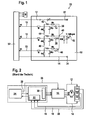
- FIG. 1 A typical application, in which Hall sensors are used both for control and for rotational speed or rotational position detection of an electronically commutated electric motor, is shown in FIG.
- Three phases of a three-phase working, electronically commutated electric motor M are controlled by an electronic control unit 10.
- the control electronics supplies via voltage supply lines 12 and 14 the power supply for Hall sensors H1, H2 and H3, via which the rotational position of the rotor of the electric motor M are detected.
- Output signals of the Hall sensors H1, H2 and H3 are fed via signal lines 16, 18 and 20 to a rotational position and direction detection device 22 whose output signals are fed to a controller 24 in which of the instantaneous rotational position and direction and the rotational speed and a desired position and / or target speed and / or desired direction of rotation dependent output signals are generated, which are supplied via a PWM signal line 26 of the control electronics 10 and fed via a further line 28 of a commutator 30, in which the necessary reversals of the motor M are calculated, then the control electronics 10 whose outputs control the windings of the motor M to the polarity and signal level (pulse width modulated signal).
- the units 22, 24, 30 and 10 with the associated connection lines are, for example, in an electronic control unit for controlling the motor M and for supplying power to the Hall sensors H1, H2 and H3, which are integral parts of the motor M united.
- the output signals of the Hall sensors alternate depending on the rotational position of the rotor of the motor M between a high level and a low level, wherein the Hall sensors are arranged such that constantly at least one high-level signal is present. Constantly is not to be understood in the strict sense of the word, since the high-level signals do not have to overlap.
- the output signals of the Hall sensors are advantageously digitized by corresponding A / D converter circuits, so that they are available in digital form (0 or 1) in the device 22 for evaluation.
- a problem of the arrangement described is that, for example due to high ohmic resistances or other errors in the power supply lines 12 or 14, the supply voltage of the Hall sensors below the specified supply voltage drops, so that their output signals for evaluation are insufficient and the rotational position of the motor M no longer be recognized. Since the state of the digitalized output signals of the Hall sensors is frozen in this case, the current error case is not recognized when the frozen Hall state is a plausible state. This is illustrated by Table 1, which indicates Hall sensor conditions.
- the fourth column indicates a frozen state in the event of an error, in which the output signal of the Hall sensors H1 and H3 is at low level and the output signal of the Hall sensor H2 is high.
- This condition is a plausible condition that is not recognized as an error.
- Error states are states 0 and 7, in which all output signals are simultaneously 0 or simultaneously 1, which can not be the case if the Hall sensors and the proper supply voltage function properly.
- the invention has for its object to provide a way by which an insufficient supply voltage of the Hall sensors can be reliably detected, so that the possibility that a frozen error case is considered plausible and is not recognized as an error, is excluded.
- a solution to this problem is achieved with a method for detecting an undervoltage supply of at least one Hall sensor, which detects a Hall sensor movement of a component and alternately emits a high level and a low level signal with moving component, the height of the high level signal from the height of the supply voltage of the Hall sensor Depends on which method that the height of the high-level signal is determined and falls below a predetermined threshold value is interpreted as an under voltage supply.
- An advantageous embodiment of the method according to the invention is that the movement of the component is detected by a plurality of Hall sensors (H1, H2, H3) located at a common supply voltage whose number and arrangement is such that at least one Hall sensor constantly outputs a high level signal Height is determined, and falls below a predetermined threshold by the high level signal is interpreted as undervoltage supply.
- a plurality of Hall sensors H1, H2, H3 located at a common supply voltage whose number and arrangement is such that at least one Hall sensor constantly outputs a high level signal Height is determined, and falls below a predetermined threshold by the high level signal is interpreted as undervoltage supply.
- An inventive device for detecting an undervoltage supply of a plurality of lying at a common voltage source Hall sensors which are arranged such that they emit at its output when moving a component alternately a high level signal and a low level signal, wherein the height of the high level signal depends on the level of the supply voltage and the arrangement and number of Hall sensors is such that constantly at least one Hall sensor emits a high level signal, characterized in that the outputs of the Hall sensors parallel to each other at a Voltage measuring means are located at the input of a voltage which corresponds substantially to the highest voltage of the output signals, and that the voltage measuring means generates an error signal when their input voltage falls below a predetermined threshold.
- each Hall sensor is connected via a rectifier diode to the input of the voltage measuring device.
- a resistor and, in parallel thereto, a capacitor are arranged between the input of the voltage measuring device and each Hall sensor, and via which the input of the voltage measuring device is connected to ground.
- the basic idea underlying the invention of determining the effective supply voltage of the Hall sensor (s) by evaluating their output signals can be used for a very wide variety of applications.
- the invention is used particularly advantageously for arrangements in which the Hall sensors form the rotational state determination sensor system of an electronically commutated electric motor.
- one of the outputs of the Hall sensors with the voltage measuring device and an evaluation circuit for comparing the input voltage of the voltage measuring device with the threshold value containing circuit are arranged on a circuit board.
- the error detection security can be detected by means for measuring a.
- Supply of the Hall sensors serving output voltage can be increased.
- a total of 32 designated electronic control device includes the modules 10, 22, 24 and 30.
- the power supply of the Hall sensors H1, H2 and H3 (Fig. 2) via terminals 33 and 34 at the ends of the supply lines 12 and 14th
- the output signals of the Hall sensors H1, H2 and H3 are supplied to the signal lines 16, 18 and 20 via the terminals 36, 38 and 40.
- For filtering the signals lying on the lines 16, 18 and 20 are each a resistor and a capacitor, which are connected in parallel.
- For adaptation serves a lying in the respective signal line ohmic resistance.
- the signal lines 16, 18 and 20 are each connected via a rectifier diode 42, 44 and 46 and an ohmic resistor to a common point 48 which is connected via a consisting of a resistor and a capacitor filter circuit with a socket 50 to which a signal can be tapped, which corresponds approximately to the respective maximum signal voltage of the Hall sensors H1, H2 and H3 and which is delayed with a given by the filter circuit time constant with respect to the respective maximum output voltage and optionally decays.
- the output voltages of the Hall sensors H1, H2 and H3 are "codified".
- the voltage which can be picked off at the socket 50 is largely independent of whether the output signals from one or two Hall sensors are at a high level.
- the aim of the illustrated in Fig. 1 circuit is that the tapped off at the socket 50 voltage is as independent as possible, whether one or more output signals of the Hall sensors are at their high level, thereby creating the smallest possible signal swing.
- a supply voltage which is too low at the Hall sensors and whose height influences the height of the high-level signal can be determined as accurately as possible.
- the decay time constant must be small enough to detect a drop in supply voltage fast enough.
- the voltage applied to the socket 50 is compared in a not shown evaluation circuit with a threshold value, which is selected such that above the threshold, a perfect processing of the output signals of the Hall sensors is guaranteed.
- Typical values are for example a stroke of the "grounded" Hall voltage at the socket 50 of less than 200 mV.
- a time constant of filtered, scaled hollow voltage of about 1 msec, for example, the A / D converted signal is sampled every 2.5 msec.
- the output voltage of the electronic control device 32 lying on the supply lines 12 and 14 is measured directly in the latter, so that fault-free operation of the electronic control device 32 can be ensured. Further, it is expedient to check the logic of the output signals of the Hall sensors in the electronic control device 32, so that the static error case of Table 1 can be detected.
- Table 2 below shows different possible error states and their recognizability.
- Table 2 Error conditions Status U Hall SG U Hall level Logic Hall signal malfunction comment 1 nok nok nok SG / cabling SG can be diagnosed when motor is disconnected 2 OK OK OK - Error-free state 3 OK OK nok Wiring / Hall sensors 4 OK nok OK cabling Contact resistance in cable / plug 5 OK nok OK Wiring / Hall sensor
- U Hall SG means the voltage applied to the supply lines 12 and 14 at the output of the electronic control device 32 and measured in the electronic control device 32.
- U Hall level means the voltage which can be removed at the socket 50.
- the error conditions 1, 3 and 5 can be detected by checking the output voltage of the electronic control device 32 or checking the logic of the output signals of the Hall sensors
- the error state 4 namely an error in the cabling of the Hall sensor only about the described evaluation of Output signals of the Hall sensors can be identified by determining the voltage at the socket 50.
- the described with reference to FIG. 1 circuit can be arranged in total on a board 52, which is for example arranged directly on the motor M and contains a specified AISIG.
- Exemplary values for the proper voltage at the output of the electronic controller 32, which is directly measured back in this, are between 4.5 and 5.5 volts.
- the signal level of the grounded Hall signals at jack 50 is rated as OK if it is between 4.0 to 6.0 volts.
- the state of the three reverb signals is OK unless it is 000 or 111.
- the evaluating or comparison circuit with an adjustable threshold value used for evaluating the signal level at the socket 50 and the signal level at an excessively low signal level is an error signal can be arranged on the board 52 or in the electronic control device 32.
Landscapes
- Physics & Mathematics (AREA)
- General Physics & Mathematics (AREA)
- Measuring Instrument Details And Bridges, And Automatic Balancing Devices (AREA)
- Transmission And Conversion Of Sensor Element Output (AREA)
- Measurement Of Current Or Voltage (AREA)
- Measuring Magnetic Variables (AREA)
- Control Of Motors That Do Not Use Commutators (AREA)
- Hall/Mr Elements (AREA)
Applications Claiming Priority (1)
| Application Number | Priority Date | Filing Date | Title |
|---|---|---|---|
| DE102006037132 | 2006-08-09 |
Publications (4)
| Publication Number | Publication Date |
|---|---|
| EP1890159A2 true EP1890159A2 (fr) | 2008-02-20 |
| EP1890159A3 EP1890159A3 (fr) | 2009-04-22 |
| EP1890159B1 EP1890159B1 (fr) | 2010-09-22 |
| EP1890159B8 EP1890159B8 (fr) | 2010-11-24 |
Family
ID=38800943
Family Applications (1)
| Application Number | Title | Priority Date | Filing Date |
|---|---|---|---|
| EP07013188A Not-in-force EP1890159B8 (fr) | 2006-08-09 | 2007-07-05 | Procédé et dispositif destinés à la détection d'une alimentation en sous-tension d'au moins un capteur Hall |
Country Status (3)
| Country | Link |
|---|---|
| EP (1) | EP1890159B8 (fr) |
| AT (1) | ATE482401T1 (fr) |
| DE (1) | DE502007005127D1 (fr) |
Cited By (2)
| Publication number | Priority date | Publication date | Assignee | Title |
|---|---|---|---|---|
| WO2016041749A1 (fr) * | 2014-09-17 | 2016-03-24 | Continental Teves Ag & Co. Ohg | Capteur de vitesse de rotation de roue |
| WO2025093764A1 (fr) * | 2023-11-03 | 2025-05-08 | Brose Fahrzeugteile SE & Co. Kommanditgesellschaft, Coburg | Dispositif de détection d'un sens de rotation d'un moteur électrique et procédé de montage pour monter un système d'entraînement |
Citations (3)
| Publication number | Priority date | Publication date | Assignee | Title |
|---|---|---|---|---|
| US5001406A (en) | 1988-10-19 | 1991-03-19 | Spectra-Physics, Inc. | Brushless DC motor speed control via power supply voltage level control |
| US20060006822A1 (en) | 2004-07-10 | 2006-01-12 | Luk Lamellen Und Kupplungsbau Beteiligungs Kg | Method for operating an electronically commutated (EC) motor |
| EP1339578B1 (fr) | 2000-11-22 | 2006-04-19 | Continental Teves AG & Co. oHG | Capteur magnetique actif destine a des systemes de freinage electriques |
-
2007
- 2007-07-05 DE DE502007005127T patent/DE502007005127D1/de active Active
- 2007-07-05 EP EP07013188A patent/EP1890159B8/fr not_active Not-in-force
- 2007-07-05 AT AT07013188T patent/ATE482401T1/de active
Patent Citations (3)
| Publication number | Priority date | Publication date | Assignee | Title |
|---|---|---|---|---|
| US5001406A (en) | 1988-10-19 | 1991-03-19 | Spectra-Physics, Inc. | Brushless DC motor speed control via power supply voltage level control |
| EP1339578B1 (fr) | 2000-11-22 | 2006-04-19 | Continental Teves AG & Co. oHG | Capteur magnetique actif destine a des systemes de freinage electriques |
| US20060006822A1 (en) | 2004-07-10 | 2006-01-12 | Luk Lamellen Und Kupplungsbau Beteiligungs Kg | Method for operating an electronically commutated (EC) motor |
Cited By (3)
| Publication number | Priority date | Publication date | Assignee | Title |
|---|---|---|---|---|
| WO2016041749A1 (fr) * | 2014-09-17 | 2016-03-24 | Continental Teves Ag & Co. Ohg | Capteur de vitesse de rotation de roue |
| US10641785B2 (en) | 2014-09-17 | 2020-05-05 | Continental Teves Ag & Co. Ohg | Wheel speed sensor |
| WO2025093764A1 (fr) * | 2023-11-03 | 2025-05-08 | Brose Fahrzeugteile SE & Co. Kommanditgesellschaft, Coburg | Dispositif de détection d'un sens de rotation d'un moteur électrique et procédé de montage pour monter un système d'entraînement |
Also Published As
| Publication number | Publication date |
|---|---|
| EP1890159B1 (fr) | 2010-09-22 |
| EP1890159B8 (fr) | 2010-11-24 |
| EP1890159A3 (fr) | 2009-04-22 |
| DE502007005127D1 (de) | 2010-11-04 |
| ATE482401T1 (de) | 2010-10-15 |
Similar Documents
| Publication | Publication Date | Title |
|---|---|---|
| DE102010007349B4 (de) | Anomalienüberwachungsvorrichtung | |
| DD296763A5 (de) | Vorrichtung und verfahren zum testen von an einer gleichstromquelle angeschlossenen elektischen verbrauchern eines kraftfahrzeuges | |
| DE102016011803B4 (de) | Testvorrichtung und Verfahren zur Überprüfung eines in einem Gerät angeordneten Vibrationsmotors | |
| EP1490700B1 (fr) | Dispositif et procede de controle d'un circuit electrique | |
| DE102014212572B4 (de) | Verfahren zur Erlangung eines Hinweises, insbesondere Anfangshinweises auf eine mögliche fehlerhafte Lastbedingung eines mehrphasigen Elektromotors | |
| DE102017126754A1 (de) | Eingangsschaltung zum fehlersicheren Einlesen eines analogen Eingangssignals | |
| WO2018219504A1 (fr) | Dispositif de reconnaissance de position d'étage d'une installation d'ascenseur et procédé destiné à produire un signal d'étage | |
| DE102019200091A1 (de) | Elektronische Steuervorrichtung mit Kurzschlussschutz zur Ansteuerung eines Elektromotors einer elektromechanischen Kraftfahrzeuglenkung | |
| DE112006001925T5 (de) | Codierer, der eine Anomaliedetektionsvorrichtung und ein zugehöriges Steuersystem enthält | |
| DE102007031385A1 (de) | Verfahren und Vorrichtung zum Erkennen einer Unterspannungsversorgung wenigstens eines Hallsensors | |
| DE102009020431A1 (de) | Sensoreinrichtung und Fehlererkennungsverfahren für elektronische Schaltungen in Kraftfahrzeugen | |
| WO2004031695A1 (fr) | Systeme de mesure et procede pour controler son fonctionnement | |
| EP1890159B1 (fr) | Procédé et dispositif destinés à la détection d'une alimentation en sous-tension d'au moins un capteur Hall | |
| DE102016102177B4 (de) | Motorsteuerungsvorrichtung mit einer Funktion zur Erkennung von Fehlverdrahtung | |
| EP3953715B1 (fr) | Procédé pour déterminer un régime d'un moteur électrique à commutation électronique | |
| DE19527744A1 (de) | Eingangsschaltung für einen Raddrehzahlsensor | |
| EP1759452B1 (fr) | Regulateur de generatrice a fonction diagnostique pour des composants semi-conducteurs | |
| EP2899559B1 (fr) | Procédé de diagnostic d'un convertisseur | |
| DE102005018570A1 (de) | Kommutator für einen Elektromotor | |
| EP2126536B1 (fr) | Dispositif et procédé pour un test de fonctionnement d'un frein | |
| DE102011083217A1 (de) | Verfahren zur Überprüfung der Phasen eines elektrisch kommutierten Elektromotors | |
| DE102012223581A1 (de) | Vorrichtung und Verfahren zum Überwachen von Signalpegeln | |
| DE102014212795A1 (de) | Positionssensor für die Erfassung einer Lageposition eines Aktuators | |
| EP2517351B1 (fr) | Séparation du réseau électrique avec commutateurs pour outils électriques | |
| EP3479468B1 (fr) | Procédé et appareil permettant de vérifier un câble de connexion multiphase et un circuit de pont pour un moteur électrique multiphase |
Legal Events
| Date | Code | Title | Description |
|---|---|---|---|
| PUAI | Public reference made under article 153(3) epc to a published international application that has entered the european phase |
Free format text: ORIGINAL CODE: 0009012 |
|
| AK | Designated contracting states |
Kind code of ref document: A2 Designated state(s): AT BE BG CH CY CZ DE DK EE ES FI FR GB GR HU IE IS IT LI LT LU LV MC MT NL PL PT RO SE SI SK TR |
|
| AX | Request for extension of the european patent |
Extension state: AL BA HR MK YU |
|
| RIN1 | Information on inventor provided before grant (corrected) |
Inventor name: BUCHET, WAI-WAI Inventor name: ZIMMERMANN, MARTIN Inventor name: GERHART, JUERGEN |
|
| PUAL | Search report despatched |
Free format text: ORIGINAL CODE: 0009013 |
|
| AK | Designated contracting states |
Kind code of ref document: A3 Designated state(s): AT BE BG CH CY CZ DE DK EE ES FI FR GB GR HU IE IS IT LI LT LU LV MC MT NL PL PT RO SE SI SK TR |
|
| AX | Request for extension of the european patent |
Extension state: AL BA HR MK RS |
|
| 17P | Request for examination filed |
Effective date: 20091022 |
|
| 17Q | First examination report despatched |
Effective date: 20091116 |
|
| AKX | Designation fees paid |
Designated state(s): AT BE BG CH CY CZ DE DK EE ES FI FR GB GR HU IE IS IT LI LT LU LV MC MT NL PL PT RO SE SI SK TR |
|
| GRAP | Despatch of communication of intention to grant a patent |
Free format text: ORIGINAL CODE: EPIDOSNIGR1 |
|
| GRAS | Grant fee paid |
Free format text: ORIGINAL CODE: EPIDOSNIGR3 |
|
| GRAA | (expected) grant |
Free format text: ORIGINAL CODE: 0009210 |
|
| AK | Designated contracting states |
Kind code of ref document: B1 Designated state(s): AT BE BG CH CY CZ DE DK EE ES FI FR GB GR HU IE IS IT LI LT LU LV MC MT NL PL PT RO SE SI SK TR |
|
| REG | Reference to a national code |
Ref country code: GB Ref legal event code: FG4D Free format text: NOT ENGLISH |
|
| REG | Reference to a national code |
Ref country code: CH Ref legal event code: EP |
|
| REG | Reference to a national code |
Ref country code: IE Ref legal event code: FG4D Free format text: LANGUAGE OF EP DOCUMENT: GERMAN |
|
| RAP2 | Party data changed (patent owner data changed or rights of a patent transferred) |
Owner name: SCHAEFFLER TECHNOLOGIES GMBH & CO. KG |
|
| REF | Corresponds to: |
Ref document number: 502007005127 Country of ref document: DE Date of ref document: 20101104 Kind code of ref document: P |
|
| PG25 | Lapsed in a contracting state [announced via postgrant information from national office to epo] |
Ref country code: FI Free format text: LAPSE BECAUSE OF FAILURE TO SUBMIT A TRANSLATION OF THE DESCRIPTION OR TO PAY THE FEE WITHIN THE PRESCRIBED TIME-LIMIT Effective date: 20100922 Ref country code: LT Free format text: LAPSE BECAUSE OF FAILURE TO SUBMIT A TRANSLATION OF THE DESCRIPTION OR TO PAY THE FEE WITHIN THE PRESCRIBED TIME-LIMIT Effective date: 20100922 |
|
| REG | Reference to a national code |
Ref country code: NL Ref legal event code: VDEP Effective date: 20100922 |
|
| LTIE | Lt: invalidation of european patent or patent extension |
Effective date: 20100922 |
|
| PG25 | Lapsed in a contracting state [announced via postgrant information from national office to epo] |
Ref country code: SI Free format text: LAPSE BECAUSE OF FAILURE TO SUBMIT A TRANSLATION OF THE DESCRIPTION OR TO PAY THE FEE WITHIN THE PRESCRIBED TIME-LIMIT Effective date: 20100922 Ref country code: PL Free format text: LAPSE BECAUSE OF FAILURE TO SUBMIT A TRANSLATION OF THE DESCRIPTION OR TO PAY THE FEE WITHIN THE PRESCRIBED TIME-LIMIT Effective date: 20100922 |
|
| PG25 | Lapsed in a contracting state [announced via postgrant information from national office to epo] |
Ref country code: SE Free format text: LAPSE BECAUSE OF FAILURE TO SUBMIT A TRANSLATION OF THE DESCRIPTION OR TO PAY THE FEE WITHIN THE PRESCRIBED TIME-LIMIT Effective date: 20100922 Ref country code: GR Free format text: LAPSE BECAUSE OF FAILURE TO SUBMIT A TRANSLATION OF THE DESCRIPTION OR TO PAY THE FEE WITHIN THE PRESCRIBED TIME-LIMIT Effective date: 20101223 Ref country code: LV Free format text: LAPSE BECAUSE OF FAILURE TO SUBMIT A TRANSLATION OF THE DESCRIPTION OR TO PAY THE FEE WITHIN THE PRESCRIBED TIME-LIMIT Effective date: 20100922 |
|
| REG | Reference to a national code |
Ref country code: IE Ref legal event code: FD4D |
|
| PG25 | Lapsed in a contracting state [announced via postgrant information from national office to epo] |
Ref country code: IE Free format text: LAPSE BECAUSE OF FAILURE TO SUBMIT A TRANSLATION OF THE DESCRIPTION OR TO PAY THE FEE WITHIN THE PRESCRIBED TIME-LIMIT Effective date: 20100922 |
|
| PG25 | Lapsed in a contracting state [announced via postgrant information from national office to epo] |
Ref country code: SK Free format text: LAPSE BECAUSE OF FAILURE TO SUBMIT A TRANSLATION OF THE DESCRIPTION OR TO PAY THE FEE WITHIN THE PRESCRIBED TIME-LIMIT Effective date: 20100922 Ref country code: RO Free format text: LAPSE BECAUSE OF FAILURE TO SUBMIT A TRANSLATION OF THE DESCRIPTION OR TO PAY THE FEE WITHIN THE PRESCRIBED TIME-LIMIT Effective date: 20100922 Ref country code: IS Free format text: LAPSE BECAUSE OF FAILURE TO SUBMIT A TRANSLATION OF THE DESCRIPTION OR TO PAY THE FEE WITHIN THE PRESCRIBED TIME-LIMIT Effective date: 20110122 Ref country code: EE Free format text: LAPSE BECAUSE OF FAILURE TO SUBMIT A TRANSLATION OF THE DESCRIPTION OR TO PAY THE FEE WITHIN THE PRESCRIBED TIME-LIMIT Effective date: 20100922 Ref country code: IT Free format text: LAPSE BECAUSE OF FAILURE TO SUBMIT A TRANSLATION OF THE DESCRIPTION OR TO PAY THE FEE WITHIN THE PRESCRIBED TIME-LIMIT Effective date: 20100922 Ref country code: NL Free format text: LAPSE BECAUSE OF FAILURE TO SUBMIT A TRANSLATION OF THE DESCRIPTION OR TO PAY THE FEE WITHIN THE PRESCRIBED TIME-LIMIT Effective date: 20100922 Ref country code: CZ Free format text: LAPSE BECAUSE OF FAILURE TO SUBMIT A TRANSLATION OF THE DESCRIPTION OR TO PAY THE FEE WITHIN THE PRESCRIBED TIME-LIMIT Effective date: 20100922 Ref country code: PT Free format text: LAPSE BECAUSE OF FAILURE TO SUBMIT A TRANSLATION OF THE DESCRIPTION OR TO PAY THE FEE WITHIN THE PRESCRIBED TIME-LIMIT Effective date: 20110124 |
|
| PG25 | Lapsed in a contracting state [announced via postgrant information from national office to epo] |
Ref country code: ES Free format text: LAPSE BECAUSE OF FAILURE TO SUBMIT A TRANSLATION OF THE DESCRIPTION OR TO PAY THE FEE WITHIN THE PRESCRIBED TIME-LIMIT Effective date: 20110102 |
|
| PLBE | No opposition filed within time limit |
Free format text: ORIGINAL CODE: 0009261 |
|
| STAA | Information on the status of an ep patent application or granted ep patent |
Free format text: STATUS: NO OPPOSITION FILED WITHIN TIME LIMIT |
|
| 26N | No opposition filed |
Effective date: 20110623 |
|
| PG25 | Lapsed in a contracting state [announced via postgrant information from national office to epo] |
Ref country code: DK Free format text: LAPSE BECAUSE OF FAILURE TO SUBMIT A TRANSLATION OF THE DESCRIPTION OR TO PAY THE FEE WITHIN THE PRESCRIBED TIME-LIMIT Effective date: 20100922 |
|
| REG | Reference to a national code |
Ref country code: DE Ref legal event code: R097 Ref document number: 502007005127 Country of ref document: DE Effective date: 20110623 |
|
| PG25 | Lapsed in a contracting state [announced via postgrant information from national office to epo] |
Ref country code: MT Free format text: LAPSE BECAUSE OF FAILURE TO SUBMIT A TRANSLATION OF THE DESCRIPTION OR TO PAY THE FEE WITHIN THE PRESCRIBED TIME-LIMIT Effective date: 20100922 |
|
| BERE | Be: lapsed |
Owner name: LUK LAMELLEN UND KUPPLUNGSBAU BETEILIGUNGS K.G. Effective date: 20110731 |
|
| PG25 | Lapsed in a contracting state [announced via postgrant information from national office to epo] |
Ref country code: MC Free format text: LAPSE BECAUSE OF NON-PAYMENT OF DUE FEES Effective date: 20110731 |
|
| REG | Reference to a national code |
Ref country code: CH Ref legal event code: PL |
|
| GBPC | Gb: european patent ceased through non-payment of renewal fee |
Effective date: 20110705 |
|
| PG25 | Lapsed in a contracting state [announced via postgrant information from national office to epo] |
Ref country code: BE Free format text: LAPSE BECAUSE OF NON-PAYMENT OF DUE FEES Effective date: 20110731 Ref country code: LI Free format text: LAPSE BECAUSE OF NON-PAYMENT OF DUE FEES Effective date: 20110731 Ref country code: CH Free format text: LAPSE BECAUSE OF NON-PAYMENT OF DUE FEES Effective date: 20110731 |
|
| PG25 | Lapsed in a contracting state [announced via postgrant information from national office to epo] |
Ref country code: GB Free format text: LAPSE BECAUSE OF NON-PAYMENT OF DUE FEES Effective date: 20110705 |
|
| REG | Reference to a national code |
Ref country code: DE Ref legal event code: R081 Ref document number: 502007005127 Country of ref document: DE Owner name: SCHAEFFLER TECHNOLOGIES AG & CO. KG, DE Free format text: FORMER OWNER: SCHAEFFLER TECHNOLOGIES GMBH & CO. KG, 91074 HERZOGENAURACH, DE Effective date: 20120828 Ref country code: DE Ref legal event code: R081 Ref document number: 502007005127 Country of ref document: DE Owner name: SCHAEFFLER TECHNOLOGIES GMBH & CO. KG, DE Free format text: FORMER OWNER: SCHAEFFLER TECHNOLOGIES GMBH & CO. KG, 91074 HERZOGENAURACH, DE Effective date: 20120828 |
|
| PG25 | Lapsed in a contracting state [announced via postgrant information from national office to epo] |
Ref country code: LU Free format text: LAPSE BECAUSE OF NON-PAYMENT OF DUE FEES Effective date: 20110705 Ref country code: CY Free format text: LAPSE BECAUSE OF EXPIRATION OF PROTECTION Effective date: 20100922 |
|
| REG | Reference to a national code |
Ref country code: AT Ref legal event code: MM01 Ref document number: 482401 Country of ref document: AT Kind code of ref document: T Effective date: 20120731 |
|
| PG25 | Lapsed in a contracting state [announced via postgrant information from national office to epo] |
Ref country code: BG Free format text: LAPSE BECAUSE OF FAILURE TO SUBMIT A TRANSLATION OF THE DESCRIPTION OR TO PAY THE FEE WITHIN THE PRESCRIBED TIME-LIMIT Effective date: 20101222 Ref country code: TR Free format text: LAPSE BECAUSE OF FAILURE TO SUBMIT A TRANSLATION OF THE DESCRIPTION OR TO PAY THE FEE WITHIN THE PRESCRIBED TIME-LIMIT Effective date: 20100922 |
|
| PG25 | Lapsed in a contracting state [announced via postgrant information from national office to epo] |
Ref country code: HU Free format text: LAPSE BECAUSE OF FAILURE TO SUBMIT A TRANSLATION OF THE DESCRIPTION OR TO PAY THE FEE WITHIN THE PRESCRIBED TIME-LIMIT Effective date: 20100922 Ref country code: AT Free format text: LAPSE BECAUSE OF NON-PAYMENT OF DUE FEES Effective date: 20120731 |
|
| REG | Reference to a national code |
Ref country code: DE Ref legal event code: R081 Ref document number: 502007005127 Country of ref document: DE Owner name: SCHAEFFLER TECHNOLOGIES GMBH & CO. KG, DE Free format text: FORMER OWNER: SCHAEFFLER TECHNOLOGIES AG & CO. KG, 91074 HERZOGENAURACH, DE Effective date: 20140214 Ref country code: DE Ref legal event code: R081 Ref document number: 502007005127 Country of ref document: DE Owner name: SCHAEFFLER TECHNOLOGIES AG & CO. KG, DE Free format text: FORMER OWNER: SCHAEFFLER TECHNOLOGIES AG & CO. KG, 91074 HERZOGENAURACH, DE Effective date: 20140214 |
|
| REG | Reference to a national code |
Ref country code: DE Ref legal event code: R081 Ref document number: 502007005127 Country of ref document: DE Owner name: SCHAEFFLER TECHNOLOGIES AG & CO. KG, DE Free format text: FORMER OWNER: SCHAEFFLER TECHNOLOGIES GMBH & CO. KG, 91074 HERZOGENAURACH, DE Effective date: 20150223 |
|
| REG | Reference to a national code |
Ref country code: FR Ref legal event code: PLFP Year of fee payment: 9 |
|
| REG | Reference to a national code |
Ref country code: FR Ref legal event code: PLFP Year of fee payment: 10 |
|
| REG | Reference to a national code |
Ref country code: FR Ref legal event code: PLFP Year of fee payment: 11 |
|
| REG | Reference to a national code |
Ref country code: FR Ref legal event code: PLFP Year of fee payment: 12 |
|
| PGFP | Annual fee paid to national office [announced via postgrant information from national office to epo] |
Ref country code: DE Payment date: 20220920 Year of fee payment: 16 |
|
| PGFP | Annual fee paid to national office [announced via postgrant information from national office to epo] |
Ref country code: FR Payment date: 20220720 Year of fee payment: 16 |
|
| P01 | Opt-out of the competence of the unified patent court (upc) registered |
Effective date: 20230522 |
|
| REG | Reference to a national code |
Ref country code: DE Ref legal event code: R119 Ref document number: 502007005127 Country of ref document: DE |
|
| PG25 | Lapsed in a contracting state [announced via postgrant information from national office to epo] |
Ref country code: DE Free format text: LAPSE BECAUSE OF NON-PAYMENT OF DUE FEES Effective date: 20240201 |
|
| PG25 | Lapsed in a contracting state [announced via postgrant information from national office to epo] |
Ref country code: FR Free format text: LAPSE BECAUSE OF NON-PAYMENT OF DUE FEES Effective date: 20230731 |