EP1890429B1 - Élément de matériel de mise en réseau pour coupler des éléments de réseau informatique et procédé d'affichage d'une carte d'agencement du réseau sur celui-ci - Google Patents
Élément de matériel de mise en réseau pour coupler des éléments de réseau informatique et procédé d'affichage d'une carte d'agencement du réseau sur celui-ci Download PDFInfo
- Publication number
- EP1890429B1 EP1890429B1 EP07253235.1A EP07253235A EP1890429B1 EP 1890429 B1 EP1890429 B1 EP 1890429B1 EP 07253235 A EP07253235 A EP 07253235A EP 1890429 B1 EP1890429 B1 EP 1890429B1
- Authority
- EP
- European Patent Office
- Prior art keywords
- hardware element
- networking hardware
- computer network
- network
- network elements
- Prior art date
- Legal status (The legal status is an assumption and is not a legal conclusion. Google has not performed a legal analysis and makes no representation as to the accuracy of the status listed.)
- Not-in-force
Links
Images


Classifications
-
- H—ELECTRICITY
- H04—ELECTRIC COMMUNICATION TECHNIQUE
- H04L—TRANSMISSION OF DIGITAL INFORMATION, e.g. TELEGRAPHIC COMMUNICATION
- H04L41/00—Arrangements for maintenance, administration or management of data switching networks, e.g. of packet switching networks
- H04L41/22—Arrangements for maintenance, administration or management of data switching networks, e.g. of packet switching networks comprising specially adapted graphical user interfaces [GUI]
-
- H—ELECTRICITY
- H04—ELECTRIC COMMUNICATION TECHNIQUE
- H04L—TRANSMISSION OF DIGITAL INFORMATION, e.g. TELEGRAPHIC COMMUNICATION
- H04L41/00—Arrangements for maintenance, administration or management of data switching networks, e.g. of packet switching networks
- H04L41/12—Discovery or management of network topologies
Definitions
- This invention relates generally to computer networks, and relates more particularly to the monitoring and management of computer networks.
- Computer networks include a variety of elements such as computers, printers, modems, and the like. Computer networks also often include networking hardware elements, such as wireless and/or wired routers, to electrically couple the various computer network elements to each other. From time to time, however, these computer networks have performance problems. Computer network administrators or other users attempting to address such performance problems often receive information about the computer system through a display on the networking hardware elements, and/or through a user interface on the computers.
- Existing user interfaces vary widely with respect to the nature and the amount of interaction they allow, but none are ideal in terms of the diagnostic information and problem solving advice they provide to the user. In addition, user interfaces are often complicated and difficult for a novice user to understand and use. Accordingly, there exists a need for an improved apparatus and method to monitor and manage computer networks.
- WO Patent Application Publication No. WO 00/56017 describes a method of using a general purpose computer as a multiprotocol label switching-enabled router.
- the general purpose computer executes software that allows it to communicate with other label switched routers using label distribution protocol.
- the general purpose computer includes a central processor, a memory, network interface cards and also typically includes local I/O such as a keyboard, a mouse, and a display device for communicating with a local user.
- U.S. Patent Application Publication No. 2003/0112958 describes a method and system for a telecommunication network management tool to represent a telecommunication network layout including a plurality of distinct network entities related to one another by a variety of attributes.
- a user interface can be used for altering a display of a network representation model to help a system manager to systematically navigate the distinct network entities and associated attributes of the selected network.
- An overlay view selector is used for effecting the display content of the representation on the user interface.
- the view selector contains a plurality of presentation modes for altering the presentation of desired elements selected from the network layout. Presentation of the selected network includes an information subset displayed over a reference view, which helps the user to maintain the information subset in context of the network layout.
- the management tool can be used to select and highlight specific network entities in context to help increase network manager efficiency in network layout and maintenance.
- European Patent Application Publication No. 1 463 236 A2 describes an information processing apparatus that includes a network device configured to be connectable to a network.
- the apparatus further includes a unit which displays a connection diagram showing a connection between the network device and the network on a display device of the information processing apparatus, a unit which performs a diagnosis of a network connection of the network device, a unit which displays a portion of the network connection where a problem of the network connection is detected by the diagnosis, on the connection diagram, and a unit which displays a message to indicate a solution to the detected problem on the display device.
- U.S. Patent Application Publication No. 2004/0218541 describes a router device that includes a router integrated circuit coupled to a processor device, one or more couplers for coupling to network systems or end users, a display for information displaying purposes, a fictitious cable detecting circuit, and a button coupled to the processor device for actuating the fictitious cable detecting circuit to detect the communication between the router device and the network systems.
- the present invention provides a networking hardware element to couple computer network elements, comprising: one or more transceivers configured to receive communication signals from one or more of the computer network elements and to forward the communication signals to one or more of the computer network elements; a network diagnostic mechanism in the networking hardware element that is capable of: iteratively scanning the transceivers to monitor the computer network elements; mapping the computer network elements; and determining a connection status for the computer network elements coupled to the networking hardware element based on monitoring the computer network elements; and a display at a surface of the networking hardware element and capable of: communicating with the network diagnostic mechanism; and displaying a network layout map of the computer network elements based on the mapping by the network diagnostic mechanism, the network layout map being iconographic and comprising: representations of the computer network elements; and representations of the connection status of the computer network elements; wherein the networking hardware element is a non-general purpose computer unit selected from the group consisting essentially of a router, a hub or a switch, and the representations of the connection status are configured to be
- the present invention provides a method of displaying information about computer network elements coupled to a networking hardware element, the method comprising: using the network hardware element to iteratively scan transceivers of the networking hardware element to: monitor the computer network elements; and forward communication signals from one or more of the computer network elements to one or more different ones of the computer network elements; determining a connection status for the computer network elements; and then displaying at a surface of the networking hardware element an iconographic network layout map of: representations of the computer network elements, and representations of the connection status of any of the computer network elements, wherein: the networking hardware element is a non-general purpose computer unit selected from the group consisting essentially of a router, a hub or a switch, and the connection status is configured to be indicative of at least one of: a communication problem with at least a first one of the computer network elements; or a non-presence of at least the first one of the computer network elements.
- a networking hardware element capable of coupling computer network elements comprises a network diagnostic mechanism that is capable of mapping the computer network elements and that is also capable of determining a connection status for the computer network elements.
- the networking hardware element also comprises a display that is capable of communicating with the network diagnostic mechanism and that is also capable of displaying a network layout map of representations of the computer network elements and the connection status of the computer network elements.
- a networking hardware element to allow computer network elements to communicate with each other includes: (a) network communication ports to couple to the computer network elements; (b) a network mapping routine capable of: (1) scanning the network communication ports for communication signals; and (2) establishing a communication status for each of the network communication ports; (c) a network arrangement representation based on information from the network mapping routine, including: (1) icons for the computer network elements; and (2) the communication status of each of the network communication ports.
- a first one of the icons can represent one or more of a type of computer network element. In the same or different embodiment, the first one of the icons can indicate a quantity of the computer network elements it represents.
- the networking hardware element can further include an LCD.
- the LCD can display the network arrangement representation.
- the networking hardware element can further include: (a) an LCD; (b) a network troubleshooting advice; and (c) an additional network troubleshooting advice.
- the LCD can display the network troubleshooting advice.
- the LCD can also display the additional network troubleshooting advice in response to an input pertaining to the network troubleshooting advice.
- the networking hardware element can further include: (a) an LCD; (b) a network setup advice; and (c) an additional network setup advice.
- the LCD can display the network setup advice.
- the LCD can also display the additional network setup advice in response to an input pertaining to the network setup advice.
- the computer network elements are selected from the group consisting essentially of: (a) a modem; (b) the internet; (c) one or more wired computers; (d) one or more wireless computers; and (e) a printer.
- the networking hardware element can further include a network information listing.
- the network information listing can list information selected from the group consisting essentially of (a) a network security indicator; (b) a service set identifier; (c) a network speed; and (d) a network security standard.
- the networking hardware element can further include: (a) an LCD; and (b) a network information listing,
- a first one of the icons can represent one or more of a type of computer network element.
- the LCD can display the network arrangement representation.
- the computer network elements can be selected from the group consisting essentially of (a) a modem: (b) the internet; (c) one or more wired computers; (d) one or more wireless computers, and (e) a printer.
- the network information listing lists information can be selected from the group consisting essentially of: (a) a network security indicator; (b) a service set identifier, (c) a network speed; and (d) a network security standard.
- the networking hardware element can further include: (a) a network setup advice; and (b) an additional network setup advice.
- the LCD can further display the network setup advice.
- the LCD can also indicate at least one of the icons corresponding to the network setup advice.
- the LCD can also display the additional network setup advice in response to an input pertaining to the network setup advice.
- the networking hardware element can further include: (a) a network troubleshooting advice; and (b) an additional network troubleshooting advice.
- the LCD can display the network troubleshooting advice.
- the LCD can indicate at least one of the icons corresponding to the network troubleshooting advice.
- the LCD can display the additional network troubleshooting advice in response to an input pertaining to the network troubleshooting advice.
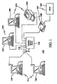
- FIG- 1 illustrates a computer network 1000.
- Computer network 1000 includes computer network elements 1010 and a networking hardware element 1100.
- Networking hardware element 1100 couples computer network elements 1010 together and, as explained in more detail hereinafter, is capable of displaying a network layout map of computer network 1000.
- Networking hardware element 1100 can represent, for example, a router, a hub such as a networking hub or a universal serial bus hub, a switch, a wireless network access point, a wireless networking card, or any other device used to couple computer network elements 1010 and to route communication signals between computer network elements 1410.
- Networking hardware element 1100 is not a computer.
- computer network elements 1010 can include at least one modem 1500, one or more wired computers 1300 connected through networking hardware element 1100 through a wired connection, one or more wireless computers 1200 connected to networking hardware element 1100 through a wireless connection, one or more printers 1400, and Internet 1604.
- Modem 1500 couples networking hardware element 1100 to Internet 1600,
- Each of computer network elements 1010 are coupled through wired or wireless connections to networking hardware element 1100 via terminals 1120 of networking hardware element 1100.
- Terminals 1120 can be mechanical terminals such as Universal Serial Bus (USB) ports, telephone jacks such as of the RJ-11 and RJ-14 types, Ethernet jacks such as of the RJ-45 type, or any other suitable connection mechanism to couple computer network elements 1010.
- Terminals 1120 can also be wireless terminals, such as one or more antennae to send and receive signals in accordance to wireless communications standards like IEEE 802.11.
- Terminals 1120 can also be referred to as router terminals when networking hardware element 1100 is a router.
- printer 1400 and modem 1500 are illustrated in FIG. 1 to be hardwired to networking hardware element 1100, one skilled in the art will understand that either or both of printer 1400 and modem 1500 can be coupled to networking hardware element 1100 via a wireless connection.
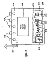
- FIG. 2 illustrates networking hardware element 1100. Regardless of whether networking hardware element 1100 is a wired device, a wireless device, or both, networking hardware element 1100 comprises one or more transceivers 2130. Transceivers 2130 are capable of sending and receiving communication signals between any of computer network elements 1010 ( FIG. 1 ) coupled to networking hardware element 1100.
- Networking hardware element 1100 further comprises a network diagnostic mechanism 2140, which is capable of monitoring transceivers 2130 in order to map each of computer network elements 1010 ( FIG. 1 ), and which is also capable of determining the connection status of each of computer network elements 1010.
- network diagnostic mechanism 2140 can be referred to as a network mapping routine, and connection status can be referred to as a communication status.
- the network mapping routine/network diagnostic mechanism 2140 may be implemented for networking hardware element 1100 through software, firmware, or hardware, or through a combination of these approaches.
- Networking hardware element 1100 is also capable of displaying a network layout map 2111.
- network layout map 2111 can be referred to as a network arrangement representation.
- Networking hardware element 1100 also comprises a display 2110, which is capable of communicating with network diagnostic mechanism 2140 and which is also capable of displaying network layout map 2111.
- display 2110 comprises a Liquid Crystal Display (LCD).
- LCD Liquid Crystal Display
- display 2110 is iconographic, denoting representations 2112 of computer network elements 1010 ( FIG. 1 ) through icons.
- display 2110 can also comprise Light Emitting Diode (LED) sets, comprising one or more LEDs, where the LED sets correspond to representations 2112 of computer network elements 1010.
- LED Light Emitting Diode
- display 2110 While communicating with network diagnostic mechanism 2140, display 2110 can access information, for example, about which of computer network elements 1010 are present, and about the connection status of each of computer network elements 1010. Display 2110 can then display network layout map 2111 on networking hardware element 1100, based on the information gathered from network diagnostic mechanism 2140.
- Network layout map 2111 on display 2110 comprises representations 2112 of computer network elements 1010 ( FIG. 1 ), along with an indication of the connection status for computer network elements 1010 (FTG. 1).
- Network layout map 2111 is arranged so as to convey information to a user about the composition of computer network 1000 through representations 2112.
- each of representations 2112 can represent a different one of computer network elements 1010 coupled to networking hardware element 1100 in computer network 1000.
- one or more of representations 2112 can represent a set or group of similar ones of computer network elements 1010, as explained in more detail hereinafter.
- Representations 2112 can also represent the interconnections between computer network elements 1100 and networking hardware element 1100.
- the connection status for each of computer network elements 1010 can also be indicated through display 2110, such as by causing the corresponding one of representations 2112 to blink and/or change colors, or by otherwise making display 2110 point to the corresponding one of representations 2112.
- the connection status can be indicated through one or more LED sets that correspond to particular computer network elements 1010.
- display 2110 is also capable of displaying a network information set 2113, which can provide users with information such as the connectivity, security, and speed of computer network 1000.
- network information set 2113 can be referred to as a network information listing.
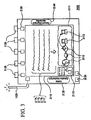
- FIG. 3 illustrates a networking hardware element 3100, which is a different embodiment of networking hardware element 1100 of FIG. 2 .
- Networking hardware element 3100 includes a display 3100.
- display 3110 is capable of accomplishing the same tasks as display 2110 on networking hardware element 1100, but is also capable of displaying a network troubleshooting advice 3114.
- Network troubleshooting advice 3114 can be presented, for example, to guide and interact with a user while troubleshooting the connection status of computer network elements 1010 coupled through networking hardware element 3100.
- display 3110 is capable of accomplishing the same tasks as display 2110 on networking hardware element 1100, but is also capable of displaying a network setup advice 3115.
- Network setup advice 3115 can be presented, for example, to interact with the user during the setup of computer network 1000 by guiding the user through the coupling of different computer network elements 1010 to networking hardware element 3110.
- user input regarding network troubleshooting advice 3114 and network setup advice 3115 may be gathered through user interface 3130.
- User interface 3130 can be implemented on networking hardware element 3100, or externally through one of computer network elements 1010 coupled to networking hardware element 3100.
- Networking hardware element 3100 can select the network troubleshooting advice 3114 and network setup advice 3115 for display 3110 through an advice selection mechanism 3120.
- Advice selection mechanism 3120 can be implemented through software, firmware, or hardware, or through a combination of these approaches, locally in networking hardware element 3100 or via one of computer network elements 1010 coupled to networking hardware element 3100.
- advice selection mechanism 3120 can be a subpart of network diagnostic mechanism 2140.
- Networking hardware element 3100 can be configured to select proper network troubleshooting advice 3114 or network setup advice 3115 via advice selection mechanism 3120, based on interaction with the user, or based on computer network information gathered via network diagnostic mechanism 2140.
- networking hardware element 3100 is capable of interpreting input from a user responding to network troubleshooting advice 3114 and/or network setup advice 3115 displayed on display 3110, and then causing display 3110 to display an additional network troubleshooting advice 3116 and/or network setup advice 3117.
- display 3110 displays the additional network troubleshooting advice 3116 and/or network setup advice 3117 in response to network diagnostic mechanism 2140 identifying a change in the connection status of one or more of computer network elements 1010 ( FIG. 1 ).
- networking hardware element 3104 is further capable of indicating on display 3110 which of representations 2112 of computer network elements 1010 correspond to network troubleshooting advice 3114 or network setup advice 3115. This indication can be done by causing corresponding representations 2112 to blink or change colors, or by otherwise making display 3110 point to or illustrate corresponding representations 2112.
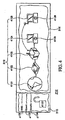
- FIG. 4 illustrates display 2110 of networking hardware elements 1100 and 3100, from FIGs. 2 and 3 , respectively.
- display 2110 comprises network layout map 2111, which includes representations 2112 of computer network elements 1010 on computer network 1000, and the connection status of computer network elements 1010.
- display 2110 can also comprise a network information set 2113, which can present information about computer network 1000 such as a network security indicator 41131, a service set identifier 41132, a network speed 41133, and a network security standard 41134.
- a network information set 2113 can present information about computer network 1000 such as a network security indicator 41131, a service set identifier 41132, a network speed 41133, and a network security standard 41134.
- Network layout map 21I1 in display 2110 illustrates a set of computer network element representations 2112, which can include an Internet connection representation 41121, a modem representation 41122, a networking hardware element representation 41123, a wired computer representation 41124, and a wireless computer representation 41125, along with representations for interconnections between computer network elements 1010.
- a first one of representations 2112 represents a plurality of one type of computer network elements 1010.
- wired computer representation 41124 can represent a set of one of more computers mechanically connected via wire or cable to computer network 1000 via networking hardware element 1100.
- wireless computer representation 41125 can represent a set of one or more computers connected wirelessly to computer network 1000 via networking hardware element 1100.
- representations 2112 can further indicate the quantity of the plurality of computer network elements 1010 they represent. This quantity indication can be accomplished, for instance, through computer network element counters 41126 corresponding to particular ones of representations 2112.
- FIG. 5 illustrates a display 5110, which is a different embodiment of display 2210 illustrated in FIG. 4 .
- Display 5110 comprises a network layout map 5111 that includes representations 5112 of computer network elements 1010.
- Network layout map 5111 and representations 5112 in FIG. 5 are similar to network layout map 2111 and representations 2112 in FIGs. 2 , 3 , and 4 .
- each of representations 5112 can represent only an individual one of computer network elements 1010, rather than being able to represent a plurality of one type of computer network elements 1010.
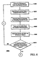
- FIG. 6 illustrates a flowchart of a method 6000 for displaying a network layout map on a networking hardware element.
- a step 6100 of method 6000 involves monitoring for computer network elements through transceivers in a networking hardware element.
- the monitoring of step 6100 can be performed by iteratively scanning for communication signals from computer network elements, which are coupled to the networking hardware element, or which are otherwise present in a computer network.
- the networking hardware element in step 6100 can be networking hardware element 1100 of FIGs. 1 and 2 , or networking hardware element 3100 of FIG. 3 .
- these same networking hardware elements can perform step 6100 in FIG. 6 for a computer network, such as computer network 1000 ( FIG. 1 ), by scanning for computer network elements, such as computer network elements 1010 ( FIG. 1 ), through network diagnostic mechanism 2140, as described in FIG. 2 .
- a step 6200 of method 6000 involves determining a connection status for any of the computer network elements coupled to the networking hardware element. This step can be accomplished, for example, by processing information gathered in step 6100 from monitoring transceivers in the networking hardware element. In the same or a different example, determining the connection status can be accomplished through a mechanism such as network diagnostic mechanism 2140, as described in FIG. 2 . In the same or a different example, steps 6100 and 6200 of method 6000 can be subparts of a single step.
- a step 6300 of method 6000 in FIG. 6 involves displaying a network layout map by showing the computer network elements present in the computer network and the interconnections between the computer network elements.
- the network layout map can be based on information gathered in step 6200 about the computer network elements and about the connection status of the computer network elements.
- step 6300 can produce a network layout map on a display similar to network layout map 2111 on display 2110 in FIGs. 2 and 4 , and/or similar to network layout map 5111 on display 5110 in FIG. 5 .
- a step 6400 of method 6000 in FIG. 6 involves displaying a connection status for the computer network elements displayed on network layout map of step 6300.
- the connection status of the computer network elements can be indicated, as described in FIG. 2 and FIG. 3 , such as by causing any appropriate ones of representations 2112 to blink or change colors, or by otherwise making display 2110 point to any appropriate ones of representations 2112.
- steps 6300 and 6400 of method 6000 can be subparts of a single step, or their sequence can be reversed.
- a step 6500 of method 6000 involves displaying a network information set.
- the information to be displayed can be determined, for instance, by processing the information gathered in step 6100 from monitoring the transceivers in the networking hardware element.
- the network information set can be indicated as illustrated by network information set 2113 from FIG. 4 .
- steps 6300, 6400, and 6500 of method 6000 can be subparts of a single step, or their sequence can be changed.
- a decision step 6600 of method 6000 involves determining whether the networking hardware element is equipped to render a network setup and/or troubleshooting advice to a user.
- the network setup and/or troubleshooting advice can be as described for network troubleshooting advice 3114 and/or network setup advice 3115 in FIG. 3 . If the networking hardware element is not equipped to provide the network setup and/or troubleshooting advice, then method 6000 proceeds along a path "A", which repeats method 6000 at step 6100. If the networking hardware element is equipped to provide the network setup and/or troubleshooting advice, then method 6000 proceeds along a path "B", which continues method 6000 as a method 7000, as shown hereinafter in FIG. 7 .
- FIG. 7 illustrates a flowchart of method 7000 for displaying a network setup and/or troubleshooting advice on a networking hardware element.
- the network setup and/or troubleshooting advice can encompass both setup advice and troubleshooting advice, such as network setup advice 3115 and network troubleshooting advice 3114 ( FIG. 3 ).
- network setup and/or troubleshooting advice can encompass only setup advice.
- network setup and/or troubleshooting advice can encompass only troubleshooting advice.
- a step 7100 of method 7000 involves determining whether displaying of network setup and/or troubleshooting advice on networking hardware element is required. In one example, step 7100 is reached from path "B" from FIG. 6 . If the network setup and/or troubleshooting advice is not required, then method 7000 ends, and the process proceeds along path "A" to step 6100 of method 6000 ( FIG. 6 ). If the network setup and/or troubleshooting advice is required, then method 7000 continues with a step 7200.
- determining in step 7100 whether the network setup and/or troubleshooting advice is required can be done via an advice selection mechanism and/or a network diagnostic mechanism in the networking hardware element, such as advice selection mechanism 3120 ( FIG. 3 ) and/or network diagnostic mechanism 2140 ( FIGS. 2 and 3 ) in networking hardware element 3100 ( FIG. 3 ).
- the advice selection mechanism can select the proper network setup and/or troubleshooting advice based on information gathered during steps 6100 and 6200 from FIG. 6 , as related to the connection status of the computer network elements in the computer network.
- the advice selection mechanism can select the proper network setup and/or troubleshooting advice based on interpreting a user input or request entered, such as described for user interface 3130 on FIG. 3 .
- a step 7200 of method 7000 in FiG, 7 involves displaying the network setup and/or troubleshooting advice, as determined in step 7100, on the networking hardware element.
- step 7200 can be accomplished on the networking hardware element through a display like display 3110 for network setup advice 3115 and network troubleshooting advice 3114 ( FIG. 3 ).
- a step 7300 of method 7000 in FIG- 7 comprises indicating on the networking hardware element any representations of the computer network elements corresponding to the network setup and/or troubleshooting advice displayed per step 7200.
- step 7300 can be implemented as described for FIG. 3 by causing corresponding representations 2112 to blink or change colors, or by otherwise making display 3110 point to or illustrate corresponding ones of representations 2112.
- method 7000 skips or omits step 7300 such that step 7200 proceeds directly to step 7400.
- a step 7400 of method 7000 in FIG. 7 comprises interpreting input responding to the network setup and/or troubleshooting advice displayed.
- the input can be entered by a user, such as described for user interface 3130 ( FIG. 3 ).
- the input can be received automatically from any mechanism monitoring computer network, such as described for network diagnostic mechanism 2140 ( FIGs. 2 and 3 ) and which can also be referred to as user input.
- method 7010 does not include step 7010.
- a step 7500 of method 7000 comprises determining whether the network setup and/or troubleshooting advice process is finished, based on interpreting input received in step 7400 or based on new information determined by the network diagnostic mechanism.
- determining whether the network setup and/or troubleshooting advice process is finished can be done via the advice selection mechanism in networking hardware element, such as advice selection mechanism 3120 in networking hardware element 3100 ( FIG. 3 ) or network diagnostic mechanism 2140 ( FIGs. 2 and 3 ). If the network setup and/or troubleshooting advice process is finished, then method 7000 ends, and the process proceeds to path "A", which repeats method 6000 ( FIG. 6 ) in a cycle starting at step 6100 ( FIG. 6 ). If the network setup and/or troubleshooting process is not yet finished, then method 7000 proceeds to a step 7600.
- Step 7600 comprises displaying on networking hardware element an additional network setup and/or troubleshooting advice. Additional network setup and/or troubleshooting advice can be selected based on the interpretation, in step 7400, of input that responded to the network setup and/or troubleshooting advice displayed previously. As an example, step 7600 can be accomplished on a networking hardware element through an advice selection mechanism, such as advice selection mechanism 3120 in networking hardware element 3100, as described for both additional network setup advice 3117 and additional network troubleshooting advice 3116 ( FIG. 3 ).
- an advice selection mechanism such as advice selection mechanism 3120 in networking hardware element 3100, as described for both additional network setup advice 3117 and additional network troubleshooting advice 3116 ( FIG. 3 ).
- step 7700 in method 7000 in FIG. 7 involves indicating on the networking hardware element any representations of the computer network elements corresponding to the displayed additional network setup and/or additional troubleshooting advice of step 7600.
- step 7700 can be implemented as described for FIG. 3 by causing corresponding representations 2112 to blink or change colors, or by otherwise making display 3110 point to or illustrate corresponding ones of representations 2112.
- method 7000 skips or omits step 7700.
- steps 7400, 7500, 7600, and 7700 can be subparts of a single step.
- step 7700 Upon completion of step 7700, method 7000 proceeds back to step 7400, waiting to interpret input responding to the network setup and/or troubleshooting advice displayed. Steps 7400 - 7700 repeat until the network setup and/or troubleshooting advice process is finished, as determined in step 7500. When network setup and/or troubleshooting advice process is finished, method 7000 proceeds from step 7500 to path "A", which repeats method 6000 in a cycle starting at step 6100.
- step 7300 could occur before step 7200. Accordingly, the detailed description of the drawings, and the drawings themselves, disclose at least one preferred embodiment of the invention, and may disclose alternative embodiments of the invention.
- embodiments and limitations disclosed herein are not dedicated to the public under the doctrine of dedication if the embodiments and/or limitations: (1) are not expressly claimed in the claims; and (2) are or are potentially equivalents of express elements and/or limitations in the claims under the doctrine of equivalents.
Landscapes
- Engineering & Computer Science (AREA)
- Computer Networks & Wireless Communication (AREA)
- Signal Processing (AREA)
- Human Computer Interaction (AREA)
- Computer And Data Communications (AREA)
- Data Exchanges In Wide-Area Networks (AREA)
- Small-Scale Networks (AREA)
- Mobile Radio Communication Systems (AREA)
Claims (19)
- Un élément de matériel de mise en réseau (1100, 3100) destiné à coupler des éléments de réseau informatique (1010), comprenant :un ou plusieurs émetteurs-récepteurs (2130) configurés de façon à recevoir des signaux de communication provenant d'un ou de plusieurs des éléments de réseau informatique et à transmettre les signaux de communication à un ou plusieurs des éléments de réseau informatique,un mécanisme de diagnostic de réseau (2140) dans l'élément de matériel de mise en réseau qui est capable de :balayer de manière itérative les émetteurs-récepteurs de façon à surveiller les éléments de réseau informatique,mettre en correspondance les éléments de réseau informatique, etdéterminer un état de connexion pour les éléments de réseau informatique couplés à l'élément de matériel de mise en réseau en fonction de la surveillance des éléments de réseau informatique,
etun dispositif d'affichage (2110, 3110, 5110) au niveau d'une surface de l'élément de matériel de mise en réseau et capable de :communiquer avec le mécanisme de diagnostic de réseau, etafficher une carte de topologie de réseau (2111, 5111) des éléments de réseau informatique en fonction de la mise en correspondance effectuée par le mécanisme de diagnostic de réseau,la carte de topologie de réseau étant iconographique et comprenant :des représentations des éléments de réseau informatique,des représentations de l'état de connexion des éléments de réseau informatique, où :l'élément de matériel de mise en réseau est une unité informatique à usage non général sélectionnée dans le groupe se composant essentiellement d'un routeur, d'un concentrateur ou d'un commutateur, etles représentations de l'état de connexion sont configurées de façon à être indicatives d'au moins un élément parmi :un problème de communication avec au moins un premier des éléments de réseau informatique, ouune non-présence d'au moins le premier des éléments de réseau informatique. - L'élément de matériel de mise en réseau selon la Revendication 1, comprenant en outre :un logement renfermant au moins partiellement :les un ou plusieurs émetteurs-récepteurs,le mécanisme de diagnostic de réseau, etle dispositif d'affichage,où les un ou plusieurs émetteurs-récepteurs sont configurés de façon à recevoir les signaux de communication provenant d'un premier des éléments de réseau informatique et à transmettre les signaux de communication à un deuxième des éléments de réseau informatique.
- L'élément de matériel de mise en réseau selon l'une quelconque des Revendications précédentes, où :les éléments de réseau informatique sont sélectionnés dans le groupe se composant essentiellement de :un modem,l'Internet,un ou plusieurs ordinateurs câblés,un ou plusieurs ordinateurs sans fil, etune imprimante.
- L'élément de matériel de mise en réseau selon l'une quelconque des Revendications précédentes, où :le dispositif d'affichage comprend en outre un dispositif d'affichage à cristaux liquides.
- L'élément de matériel de mise en réseau selon l'une quelconque des Revendications précédentes, où :une première des représentations des éléments de réseau informatique représente une pluralité d'un type d'éléments de réseau informatique.
- L'élément de matériel de mise en réseau selon la Revendication 5, où :la première des représentations des éléments de réseau informatique indique une quantité de la pluralité du type d'éléments de réseau informatique.
- L'élément de matériel de mise en réseau selon l'une quelconque des Revendications 1 à 4, où :chacune des représentations des éléments de réseau informatique représente un élément de réseau informatique individuel.
- L'élément de matériel de mise en réseau selon l'une quelconque des Revendications précédentes, où :le dispositif d'affichage est en outre capable d'afficher un ensemble d'informations de réseau sélectionné dans le groupe se composant essentiellement de :un indicateur de sécurité de réseau,un identifiant d'ensemble de services,une vitesse de réseau, etune norme de sécurité de réseau.
- L'élément de matériel de mise en réseau selon l'une quelconque des Revendications précédentes, où :le dispositif d'affichage est capable d'afficher un conseil d'établissement de réseau.
- L'élément de matériel de mise en réseau selon la Revendication 9, où :l'élément de matériel de mise en réseau est capable de :interpréter une entrée provenant d'un utilisateur en réponse au conseil d'établissement de réseau, et ensuite amener le dispositif d'affichage à afficher un conseil d'établissement de réseau additionnel.
- L'élément de matériel de mise en réseau selon la Revendication 9 ou 10, où :le dispositif d'affichage est capable d'indiquer l'une quelconque des représentations correspondant au conseil d'établissement de réseau.
- L'élément de matériel de mise en réseau selon l'une quelconque des Revendications précédentes, où :le dispositif d'affichage est capable d'afficher un conseil de dépannage de réseau.
- L'élément de matériel de mise en réseau selon la Revendication 12, comprenant en outre :l'élément de matériel de mise en réseau est capable de :interpréter une entrée provenant d'un utilisateur en réponse au conseil de dépannage de réseau, et ensuiteamener le dispositif d'affichage à afficher un conseil de dépannage de réseau additionnel.
- L'élément de matériel de mise en réseau of claims 12 ou 13, où :le dispositif d'affichage est capable d'indiquer l'une quelconque des représentations correspondant au conseil de dépannage de réseau.
- L'élément de matériel de mise en réseau selon la Revendication 1, où la carte de topologie de réseau comprend en outre des représentations d'interconnexions entre l'élément de matériel de mise en réseau et les éléments de réseau informatique.
- Un procédé d'affichage d'informations relatives à des éléments de réseau informatique (1010) couplés à un élément de matériel de mise en réseau (1100, 3100), le procédé comprenant :l'utilisation de l'élément de matériel de réseau de façon à balayer de manière itérative des émetteurs-récepteurs (2130) de l'élément de matériel de mise en réseau de façon à :où :surveiller les éléments de réseau informatique, ettransmettre des signaux de communication provenant d'un ou de plusieurs des éléments de réseau informatique à un ou plusieurs éléments différents des éléments de réseau informatique,déterminer un état de connexion pour les éléments de réseau informatique, et ensuiteafficher au niveau d'une surface de l'élément de matériel de mise en réseau une carte de topologie de réseau iconographique de :représentations des éléments de réseau informatique,représentations de l'état de connexion de l'un quelconque des éléments de réseau informatique,l'élément de matériel de mise en réseau est une unité informatique à usage non général sélectionnée dans le groupe se composant essentiellement d'un routeur, d'un concentrateur ou d'un commutateur, et l'état de connexion est configuré de façon à être indicatif d'au moins un élément parmi :un problème de communication avec au moins un premier des éléments de réseau informatique, ouune non-présence d'au moins le premier des éléments de réseau informatique.
- Le procédé selon la Revendication 16, comprenant en outre :l'affichage d'un conseil de réseau comprenant au moins un élément parmi : un conseil d'établissement au niveau de l'élément de matériel de mise en réseau ou un conseil de dépannage,l'interprétation d'une entrée utilisateur en réponse au conseil d'établissement de réseau, etl'affichage d'un conseil d'établissement de réseau additionnel en fonction de l'entrée utilisateur, le conseil de réseau additionnel comprenant au moins un élément parmi : un conseil d'établissement additionnel ou un conseil de dépannage additionnel.
- Le procédé selon la Revendication 16, comprenant en outre :l'affichage d'un conseil de dépannage au niveau de l'élément de matériel de mise en réseau,l'interprétation d'une entrée utilisateur en réponse au conseil de dépannage, etl'affichage d'un conseil de dépannage additionnel en fonction de l'entrée utilisateur.
- Le procédé selon la Revendication 16, où l'affichage de la carte de topologie de réseau iconographique implique l'affichage de représentations d'interconnexions entre l'élément de matériel de mise en réseau et les éléments de réseau informatique.
Applications Claiming Priority (1)
| Application Number | Priority Date | Filing Date | Title |
|---|---|---|---|
| US11/506,351 US7675862B2 (en) | 2006-08-17 | 2006-08-17 | Networking hardware element to couple computer network elements and method of displaying a network layout map thereon |
Publications (3)
| Publication Number | Publication Date |
|---|---|
| EP1890429A2 EP1890429A2 (fr) | 2008-02-20 |
| EP1890429A3 EP1890429A3 (fr) | 2008-05-21 |
| EP1890429B1 true EP1890429B1 (fr) | 2014-03-19 |
Family
ID=38799382
Family Applications (1)
| Application Number | Title | Priority Date | Filing Date |
|---|---|---|---|
| EP07253235.1A Not-in-force EP1890429B1 (fr) | 2006-08-17 | 2007-08-16 | Élément de matériel de mise en réseau pour coupler des éléments de réseau informatique et procédé d'affichage d'une carte d'agencement du réseau sur celui-ci |
Country Status (6)
| Country | Link |
|---|---|
| US (2) | US7675862B2 (fr) |
| EP (1) | EP1890429B1 (fr) |
| JP (1) | JP2008125052A (fr) |
| AU (1) | AU2007209808B2 (fr) |
| NZ (1) | NZ560717A (fr) |
| TW (1) | TWI431974B (fr) |
Families Citing this family (37)
| Publication number | Priority date | Publication date | Assignee | Title |
|---|---|---|---|---|
| US9584406B2 (en) | 2004-09-08 | 2017-02-28 | Cradlepoint, Inc. | Data path switching |
| US8249052B2 (en) | 2004-09-08 | 2012-08-21 | Cradlepoint, Inc. | Automated access of an enhanced command set |
| US8732808B2 (en) | 2004-09-08 | 2014-05-20 | Cradlepoint, Inc. | Data plan activation and modification |
| US9232461B2 (en) | 2004-09-08 | 2016-01-05 | Cradlepoint, Inc. | Hotspot communication limiter |
| US9237102B2 (en) | 2004-09-08 | 2016-01-12 | Cradlepoint, Inc. | Selecting a data path |
| US8477639B2 (en) * | 2004-09-08 | 2013-07-02 | Cradlepoint, Inc. | Communicating network status |
| US7817733B2 (en) * | 2006-06-30 | 2010-10-19 | Motorola Mobility, Inc. | Method and system for peak power reduction |
| US9021081B2 (en) | 2007-02-12 | 2015-04-28 | Cradlepoint, Inc. | System and method for collecting individualized network usage data in a personal hotspot wireless network |
| US8644272B2 (en) * | 2007-02-12 | 2014-02-04 | Cradlepoint, Inc. | Initiating router functions |
| US8208386B2 (en) * | 2007-03-05 | 2012-06-26 | Hewlett-Packard Development Company, L.P. | Discovery of network devices |
| KR101038882B1 (ko) * | 2007-05-31 | 2011-06-02 | 미쓰비시덴키 가부시키가이샤 | 제어 시스템 엔지니어링 장치 |
| US20090003345A1 (en) * | 2007-06-27 | 2009-01-01 | Steve Chen-Lin Chang | Network device dynamic help |
| US8316236B2 (en) * | 2007-08-31 | 2012-11-20 | Cisco Technology, Inc. | Determining security states using binary output sequences |
| WO2009064889A2 (fr) | 2007-11-14 | 2009-05-22 | Cradlepoint, Inc. | Configuration d'un routeur sans fil |
| US9812047B2 (en) | 2010-02-25 | 2017-11-07 | Manufacturing Resources International, Inc. | System and method for remotely monitoring the operating life of electronic displays |
| US10755592B2 (en) * | 2009-07-24 | 2020-08-25 | Tutor Group Limited | Facilitating diagnosis and correction of operational problems |
| TWI501209B (zh) * | 2009-07-24 | 2015-09-21 | Cheng Ta Yang | 網路互動式教學管理系統 |
| US10872535B2 (en) * | 2009-07-24 | 2020-12-22 | Tutor Group Limited | Facilitating facial recognition, augmented reality, and virtual reality in online teaching groups |
| US8712023B2 (en) * | 2010-11-23 | 2014-04-29 | Verizon Patent And Licensing Inc. | Methods and systems for aggregating and graphically representing information associated with a telecommunications circuit |
| US8555047B2 (en) | 2011-03-16 | 2013-10-08 | Rammohan Malasani | Wi-Fi router with integrated touch-screen and enhanced security features |
| JP2012221184A (ja) * | 2011-04-08 | 2012-11-12 | Buffalo Inc | 管理方法 |
| JP5807364B2 (ja) * | 2011-04-08 | 2015-11-10 | 株式会社バッファロー | 管理装置、管理方法、プログラムおよび記録媒体 |
| EP2873193B1 (fr) * | 2012-07-13 | 2023-11-01 | Adaptive Spectrum and Signal Alignment, Inc. | Procédé et système pour utiliser un agent téléchargeable pour un système, un dispositif ou une liaison de communication |
| US10411966B2 (en) | 2015-02-26 | 2019-09-10 | Red Hat, Inc. | Host network analyzer |
| WO2017044952A1 (fr) | 2015-09-10 | 2017-03-16 | Manufacturing Resources International, Inc. | Système et procédé pour la détection générale d'erreurs d'affichage |
| TWI622026B (zh) * | 2017-04-12 | 2018-04-21 | Tutor Group Ltd | Interactive teaching system |
| US10908863B2 (en) | 2018-07-12 | 2021-02-02 | Manufacturing Resources International, Inc. | System and method for providing access to co-located operations data for an electronic display |
| US11645029B2 (en) | 2018-07-12 | 2023-05-09 | Manufacturing Resources International, Inc. | Systems and methods for remotely monitoring electronic displays |
| US11402940B2 (en) | 2019-02-25 | 2022-08-02 | Manufacturing Resources International, Inc. | Monitoring the status of a touchscreen |
| WO2020176416A1 (fr) | 2019-02-25 | 2020-09-03 | Manufacturing Resources International, Inc. | Surveillance de l'état d'un écran tactile |
| JP7713210B2 (ja) * | 2021-05-15 | 2025-07-25 | 旭光電機株式会社 | 通信状態表示中継装置 |
| US11921010B2 (en) | 2021-07-28 | 2024-03-05 | Manufacturing Resources International, Inc. | Display assemblies with differential pressure sensors |
| US11965804B2 (en) | 2021-07-28 | 2024-04-23 | Manufacturing Resources International, Inc. | Display assemblies with differential pressure sensors |
| US11972672B1 (en) | 2022-10-26 | 2024-04-30 | Manufacturing Resources International, Inc. | Display assemblies providing open and unlatched alerts, systems and methods for the same |
| US12027132B1 (en) | 2023-06-27 | 2024-07-02 | Manufacturing Resources International, Inc. | Display units with automated power governing |
| US20250150108A1 (en) * | 2023-11-07 | 2025-05-08 | Leroy Robinson | Power Backup Wi-Fi Router Device |
| US12393241B1 (en) | 2024-04-04 | 2025-08-19 | Manufacturing Resources International, Inc. | Display assembly using air characteristic data to verify display assembly operating conditions, systems and methods for the same |
Citations (3)
| Publication number | Priority date | Publication date | Assignee | Title |
|---|---|---|---|---|
| US4638428A (en) * | 1983-12-14 | 1987-01-20 | Hitachi, Ltd. | Polling control method and system |
| EP0777357A2 (fr) * | 1995-11-28 | 1997-06-04 | NCR International, Inc. | Système de gestion de réseau avec surveillance et détection améliorée de noeuds |
| WO1997037292A2 (fr) * | 1996-03-21 | 1997-10-09 | Cabletron Systems, Inc. | Controleur de l'etat des connexions dans un reseau et affichage correspondant |
Family Cites Families (59)
| Publication number | Priority date | Publication date | Assignee | Title |
|---|---|---|---|---|
| US4134537A (en) | 1977-04-25 | 1979-01-16 | Transaction Technology, Inc. | Transaction terminal |
| US4814588A (en) | 1980-05-12 | 1989-03-21 | Hitachi Heating Appliances Co., Ltd. | Foodstuffs heating apparatus using information cards for automatic mode setting or the like |
| DE3340543A1 (de) | 1983-11-09 | 1985-05-23 | Bosch-Siemens Hausgeräte GmbH, 7000 Stuttgart | Haushaltgeraet mit einem bedienungsfeld |
| US4680455A (en) | 1986-03-31 | 1987-07-14 | Aurora Mechatronecs Corp. | Method of manipulating a calculation and device used therewith |
| US5113612A (en) | 1987-10-20 | 1992-05-19 | Jamco International, Inc. | Method of providing a set of instructions |
| JPH01147444U (fr) * | 1988-04-01 | 1989-10-12 | ||
| US5276789A (en) | 1990-05-14 | 1994-01-04 | Hewlett-Packard Co. | Graphic display of network topology |
| US5192150A (en) | 1991-09-10 | 1993-03-09 | Rueggeberg Karl A | Computer keyboard template selector |
| US5363366A (en) | 1993-01-11 | 1994-11-08 | Forte Networks, Inc. | Token ring local area network testing apparatus for obtaining beacon domain information |
| JP2606166B2 (ja) * | 1994-11-11 | 1997-04-30 | 日本電気株式会社 | ルーティングテーブル採集方法 |
| US5825775A (en) | 1994-11-14 | 1998-10-20 | Bay Networks, Inc. | Method and apparatus for managing an integrated router/hub |
| DE69535394T2 (de) | 1994-12-28 | 2007-10-31 | Omron Corp. | Verkehrsinformationssystem |
| JPH09181722A (ja) | 1995-12-26 | 1997-07-11 | Kodo Tsushin Syst Kenkyusho:Kk | Bgpルーティング情報を用いたネットワークマップの自動生成方式 |
| US6067093A (en) | 1996-08-14 | 2000-05-23 | Novell, Inc. | Method and apparatus for organizing objects of a network map |
| US5732464A (en) | 1996-08-21 | 1998-03-31 | Seagate Technology, Inc. | Method of facilitating installation or use of an electromechanical information-storage device drive assembly |
| JP2886150B2 (ja) * | 1997-02-03 | 1999-04-26 | キヤノン株式会社 | ネットワークデバイス制御装置及び方法 |
| JP3323881B2 (ja) | 1997-05-28 | 2002-09-09 | シャープ株式会社 | 薄型ケーブルモデム及びその載置用スタンド |
| US6160872A (en) | 1998-01-15 | 2000-12-12 | Casio Communications, Inc. | Apparatus and method for preventing disconnection of consumer premises equipment |
| NL1009688C2 (nl) | 1998-07-17 | 2000-01-18 | Koninkl Kpn Nv | Toestandsindicatie voor datacommunicatie-eindapparatuur. |
| US6177873B1 (en) | 1999-02-08 | 2001-01-23 | International Business Machines Corporation | Weather warning apparatus and method |
| WO2000056017A1 (fr) | 1999-03-12 | 2000-09-21 | Fujitsu Limited | Mise en oeuvre de routeurs de commutation de labels multi-protocole |
| WO2001001677A1 (fr) | 1999-06-28 | 2001-01-04 | United Video Properties, Inc. | Systeme et procede de guide interactif de programmes de television a plaques tournante de niches |
| JP4428844B2 (ja) * | 1999-10-01 | 2010-03-10 | キヤノン株式会社 | 情報処理装置、データ処理方法及び記録媒体 |
| US6438363B1 (en) | 1999-11-15 | 2002-08-20 | Lucent Technologies Inc. | Wireless modem alignment in a multi-cell environment |
| JP2001337763A (ja) * | 2000-05-30 | 2001-12-07 | Toshiba Corp | ネットワークシステムの構成表示方法及び表示装置 |
| US20010053134A1 (en) | 2000-06-16 | 2001-12-20 | Fillebrown Lisa A. | Router for a personal wireless network |
| JP2002190872A (ja) * | 2000-12-20 | 2002-07-05 | Nec Corp | 通信システム |
| US6885667B1 (en) | 2000-12-26 | 2005-04-26 | Cisco Technology, Inc. | Redirection to a virtual router |
| EP1246053A1 (fr) | 2001-03-26 | 2002-10-02 | Hewlett Packard Company, a Delaware Corporation | Module de communication |
| DE10117292A1 (de) | 2001-04-06 | 2002-10-10 | Bsh Bosch Siemens Hausgeraete | Verfahren zum Betreiben eines programmgesteuerten Haushaltgerätes |
| US7010593B2 (en) | 2001-04-30 | 2006-03-07 | Hewlett-Packard Development Company, L.P. | Dynamic generation of context-sensitive data and instructions for troubleshooting problem events in a computing environment |
| US6474378B1 (en) | 2001-05-07 | 2002-11-05 | S-B Power Tool Company | Plunge router having electronic depth adjustment |
| US20030112958A1 (en) | 2001-12-13 | 2003-06-19 | Luc Beaudoin | Overlay view method and system for representing network topology |
| US7965842B2 (en) | 2002-06-28 | 2011-06-21 | Wavelink Corporation | System and method for detecting unauthorized wireless access points |
| JP2004056604A (ja) * | 2002-07-23 | 2004-02-19 | Fujitsu Ltd | ネットワーク運用監視装置 |
| JP2004072211A (ja) * | 2002-08-02 | 2004-03-04 | Nec Engineering Ltd | バスリピータ装置のステータス情報収集システム、ハブ装置、及びバスリピータ装置 |
| JP2004080645A (ja) * | 2002-08-21 | 2004-03-11 | Sony Corp | ルータ装置、閉域網接続方法、閉域網接続プログラム |
| JP2004234330A (ja) | 2003-01-30 | 2004-08-19 | Toshiba Corp | 情報処理装置およびネットワーク接続診断方法 |
| US7181546B2 (en) | 2003-03-21 | 2007-02-20 | Cameo Communications Inc. | Network communication display device |
| US20040218541A1 (en) | 2003-05-02 | 2004-11-04 | Ray Lee | Router capable of detecting network system |
| US20040218544A1 (en) * | 2003-05-02 | 2004-11-04 | Ray Lee | Router capable of displaying network system |
| US7421495B2 (en) | 2003-06-27 | 2008-09-02 | Computer Associates Think, Inc. | System and method for monitoring network devices |
| US20050015644A1 (en) * | 2003-06-30 | 2005-01-20 | Microsoft Corporation | Network connection agents and troubleshooters |
| JP3961462B2 (ja) | 2003-07-30 | 2007-08-22 | インターナショナル・ビジネス・マシーンズ・コーポレーション | コンピュータ装置、無線lanシステム、プロファイルの更新方法、およびプログラム |
| US20050108557A1 (en) | 2003-10-11 | 2005-05-19 | Kayo David G. | Systems and methods for detecting and preventing unauthorized access to networked devices |
| TWI262011B (en) | 2003-11-06 | 2006-09-11 | Buffalo Inc | System, access point and method for setting of encryption key and authentication code |
| US7769837B2 (en) | 2003-12-12 | 2010-08-03 | Brother Kogyo Kabushiki Kaisha | Wireless LAN setting system and communication terminal |
| JP2005285091A (ja) | 2004-03-04 | 2005-10-13 | Sony Corp | 画像表示装置、情報端末装置、ネットワークシステム及びネットワーク設定方法 |
| US7142106B2 (en) | 2004-06-15 | 2006-11-28 | Elster Electricity, Llc | System and method of visualizing network layout and performance characteristics in a wireless network |
| US20060028398A1 (en) | 2004-07-23 | 2006-02-09 | Willmore Charles E | Wireless interactive multi-user display system and method |
| US7925729B2 (en) | 2004-12-07 | 2011-04-12 | Cisco Technology, Inc. | Network management |
| JP4414305B2 (ja) | 2004-08-19 | 2010-02-10 | 富士通株式会社 | 中継装置および中継装置の再起動方法並びに中継装置用ソフトウェアプログラム |
| JP2006157671A (ja) * | 2004-11-30 | 2006-06-15 | Toshiba Corp | 通信装置、通信システム、及び通信制御方法 |
| US20060155835A1 (en) | 2005-01-12 | 2006-07-13 | Babak Forutanpour | Schedulable network-enabled device with internal data delivery unit for use with a visusal medium and methods of use thereof |
| US7577458B2 (en) * | 2005-01-30 | 2009-08-18 | Cisco Technology, Inc. | LCD display on wireless router |
| US7603479B2 (en) | 2005-02-02 | 2009-10-13 | At&T Mobility Ii Llc | Portable diagnostic device for trouble-shooting a wireless network and a method for trouble-shooting a wireless network |
| US7587675B2 (en) * | 2006-02-28 | 2009-09-08 | Microsoft Corporation | Network map |
| US20080046561A1 (en) * | 2006-08-17 | 2008-02-21 | Belkin International, Inc. | Networking hardware element to couple computer network elements and method of displaying information thereon |
| US20080095086A1 (en) | 2006-10-23 | 2008-04-24 | Janne Linkola | Method of deploying an access point for an ip-based wireless network |
-
2006
- 2006-08-17 US US11/506,351 patent/US7675862B2/en not_active Expired - Fee Related
-
2007
- 2007-08-16 EP EP07253235.1A patent/EP1890429B1/fr not_active Not-in-force
- 2007-08-16 TW TW096130371A patent/TWI431974B/zh not_active IP Right Cessation
- 2007-08-16 JP JP2007235914A patent/JP2008125052A/ja active Pending
- 2007-08-17 AU AU2007209808A patent/AU2007209808B2/en not_active Ceased
- 2007-08-17 NZ NZ560717A patent/NZ560717A/en not_active IP Right Cessation
-
2010
- 2010-02-05 US US12/700,915 patent/US20100138519A1/en not_active Abandoned
Patent Citations (3)
| Publication number | Priority date | Publication date | Assignee | Title |
|---|---|---|---|---|
| US4638428A (en) * | 1983-12-14 | 1987-01-20 | Hitachi, Ltd. | Polling control method and system |
| EP0777357A2 (fr) * | 1995-11-28 | 1997-06-04 | NCR International, Inc. | Système de gestion de réseau avec surveillance et détection améliorée de noeuds |
| WO1997037292A2 (fr) * | 1996-03-21 | 1997-10-09 | Cabletron Systems, Inc. | Controleur de l'etat des connexions dans un reseau et affichage correspondant |
Also Published As
| Publication number | Publication date |
|---|---|
| JP2008125052A (ja) | 2008-05-29 |
| EP1890429A3 (fr) | 2008-05-21 |
| US20080043626A1 (en) | 2008-02-21 |
| NZ560717A (en) | 2008-11-28 |
| TWI431974B (zh) | 2014-03-21 |
| EP1890429A2 (fr) | 2008-02-20 |
| AU2007209808B2 (en) | 2011-09-08 |
| TW200830785A (en) | 2008-07-16 |
| US20100138519A1 (en) | 2010-06-03 |
| AU2007209808A1 (en) | 2008-03-06 |
| US7675862B2 (en) | 2010-03-09 |
Similar Documents
| Publication | Publication Date | Title |
|---|---|---|
| EP1890429B1 (fr) | Élément de matériel de mise en réseau pour coupler des éléments de réseau informatique et procédé d'affichage d'une carte d'agencement du réseau sur celui-ci | |
| EP1890430A1 (fr) | Élément de matériel de mise en réseau pour coupler des éléments de réseau informatique et procédé d'affichage d'informations sur celui-ci | |
| CN104539640B (zh) | 管理的连接性设备、系统和方法 | |
| US9989724B2 (en) | Data center network | |
| US6629269B1 (en) | Apparatus and method for trouble-shooting desktop connectivity problems | |
| JP2003289313A (ja) | 仮想ローカル・エリア・ネットワーク(vlan)を設定する方法 | |
| US8934340B1 (en) | Apparatus and method for identifying, based on an alternating pattern, a port to which a cable is connected | |
| US20210398056A1 (en) | Mobile application for assisting a technician in carrying out an electronic work order | |
| AU2012340634A1 (en) | Intelligent infrastructure management user device | |
| CN103563324A (zh) | 用于多路连接器的标识符编码方案 | |
| EP1587248B1 (fr) | Liste de connecteurs à liaisons multiples | |
| CN105242169B (zh) | 一种配线架的信号发送端和信号接收端判断装置 | |
| US20190279484A1 (en) | Visible indication of a port as configured to management functionality | |
| CN106443242A (zh) | 一种用于汽车电子产品的自动测试系统架构及测试方法 | |
| CN120045488A (zh) | 硬件控制系统、方法、装置、存储介质及电子设备 | |
| US20110313692A1 (en) | Enhanced Intelligent Patch Panel Diagnostic Management | |
| JP3241648B2 (ja) | ネットワーク接続機器管理アプリケーション開発方式 | |
| US10374920B2 (en) | Communication media and methods for providing indication of signal power to a network entity | |
| CN109002415A (zh) | 一种服务器及其基于bmc的数据传输装置 | |
| AU2007209806B2 (en) | Networking hardware element to couple computer network elements and method of displaying information thereon | |
| JP4755118B2 (ja) | 電力線通信装置、電力線通信の親機・子機判定方法、及び、電力線通信の親機特定方法 | |
| CN109120440A (zh) | 一种网口定位方法及应用其的网络设备 | |
| JP2006040302A (ja) | 通信ネットワークシステム |
Legal Events
| Date | Code | Title | Description |
|---|---|---|---|
| PUAI | Public reference made under article 153(3) epc to a published international application that has entered the european phase |
Free format text: ORIGINAL CODE: 0009012 |
|
| AK | Designated contracting states |
Kind code of ref document: A2 Designated state(s): AT BE BG CH CY CZ DE DK EE ES FI FR GB GR HU IE IS IT LI LT LU LV MC MT NL PL PT RO SE SI SK TR |
|
| AX | Request for extension of the european patent |
Extension state: AL BA HR MK YU |
|
| PUAL | Search report despatched |
Free format text: ORIGINAL CODE: 0009013 |
|
| AK | Designated contracting states |
Kind code of ref document: A3 Designated state(s): AT BE BG CH CY CZ DE DK EE ES FI FR GB GR HU IE IS IT LI LT LU LV MC MT NL PL PT RO SE SI SK TR |
|
| AX | Request for extension of the european patent |
Extension state: AL BA HR MK RS |
|
| 17P | Request for examination filed |
Effective date: 20081119 |
|
| AKX | Designation fees paid |
Designated state(s): AT BE BG CH CY CZ DE DK EE ES FI FR GB GR HU IE IS IT LI LT LU LV MC MT NL PL PT RO SE SI SK TR |
|
| 17Q | First examination report despatched |
Effective date: 20091120 |
|
| RAP1 | Party data changed (applicant data changed or rights of an application transferred) |
Owner name: BELKIN INTERNATIONAL, INC. |
|
| REG | Reference to a national code |
Ref country code: DE Ref legal event code: R079 Ref document number: 602007035638 Country of ref document: DE Free format text: PREVIOUS MAIN CLASS: H04L0012260000 Ipc: H04L0012240000 |
|
| GRAP | Despatch of communication of intention to grant a patent |
Free format text: ORIGINAL CODE: EPIDOSNIGR1 |
|
| RIC1 | Information provided on ipc code assigned before grant |
Ipc: H04L 12/26 20060101ALI20121030BHEP Ipc: H04L 12/24 20060101AFI20121030BHEP |
|
| RIN1 | Information on inventor provided before grant (corrected) |
Inventor name: LIN, STEVEN Inventor name: PHAM, ANTHONY Inventor name: BETTINO, JONATHAN Inventor name: HOARD, DAVID W. |
|
| GRAP | Despatch of communication of intention to grant a patent |
Free format text: ORIGINAL CODE: EPIDOSNIGR1 |
|
| INTG | Intention to grant announced |
Effective date: 20130802 |
|
| GRAP | Despatch of communication of intention to grant a patent |
Free format text: ORIGINAL CODE: EPIDOSNIGR1 |
|
| INTG | Intention to grant announced |
Effective date: 20140109 |
|
| GRAS | Grant fee paid |
Free format text: ORIGINAL CODE: EPIDOSNIGR3 |
|
| GRAA | (expected) grant |
Free format text: ORIGINAL CODE: 0009210 |
|
| AK | Designated contracting states |
Kind code of ref document: B1 Designated state(s): AT BE BG CH CY CZ DE DK EE ES FI FR GB GR HU IE IS IT LI LT LU LV MC MT NL PL PT RO SE SI SK TR |
|
| REG | Reference to a national code |
Ref country code: GB Ref legal event code: FG4D |
|
| REG | Reference to a national code |
Ref country code: CH Ref legal event code: EP |
|
| REG | Reference to a national code |
Ref country code: IE Ref legal event code: FG4D |
|
| REG | Reference to a national code |
Ref country code: AT Ref legal event code: REF Ref document number: 658294 Country of ref document: AT Kind code of ref document: T Effective date: 20140415 |
|
| REG | Reference to a national code |
Ref country code: DE Ref legal event code: R096 Ref document number: 602007035638 Country of ref document: DE Effective date: 20140430 |
|
| REG | Reference to a national code |
Ref country code: NL Ref legal event code: T3 |
|
| PG25 | Lapsed in a contracting state [announced via postgrant information from national office to epo] |
Ref country code: LT Free format text: LAPSE BECAUSE OF FAILURE TO SUBMIT A TRANSLATION OF THE DESCRIPTION OR TO PAY THE FEE WITHIN THE PRESCRIBED TIME-LIMIT Effective date: 20140319 |
|
| REG | Reference to a national code |
Ref country code: AT Ref legal event code: MK05 Ref document number: 658294 Country of ref document: AT Kind code of ref document: T Effective date: 20140319 |
|
| REG | Reference to a national code |
Ref country code: LT Ref legal event code: MG4D |
|
| PG25 | Lapsed in a contracting state [announced via postgrant information from national office to epo] |
Ref country code: SE Free format text: LAPSE BECAUSE OF FAILURE TO SUBMIT A TRANSLATION OF THE DESCRIPTION OR TO PAY THE FEE WITHIN THE PRESCRIBED TIME-LIMIT Effective date: 20140319 Ref country code: CY Free format text: LAPSE BECAUSE OF FAILURE TO SUBMIT A TRANSLATION OF THE DESCRIPTION OR TO PAY THE FEE WITHIN THE PRESCRIBED TIME-LIMIT Effective date: 20140319 Ref country code: FI Free format text: LAPSE BECAUSE OF FAILURE TO SUBMIT A TRANSLATION OF THE DESCRIPTION OR TO PAY THE FEE WITHIN THE PRESCRIBED TIME-LIMIT Effective date: 20140319 |
|
| PG25 | Lapsed in a contracting state [announced via postgrant information from national office to epo] |
Ref country code: LV Free format text: LAPSE BECAUSE OF FAILURE TO SUBMIT A TRANSLATION OF THE DESCRIPTION OR TO PAY THE FEE WITHIN THE PRESCRIBED TIME-LIMIT Effective date: 20140319 |
|
| PG25 | Lapsed in a contracting state [announced via postgrant information from national office to epo] |
Ref country code: BG Free format text: LAPSE BECAUSE OF FAILURE TO SUBMIT A TRANSLATION OF THE DESCRIPTION OR TO PAY THE FEE WITHIN THE PRESCRIBED TIME-LIMIT Effective date: 20140619 Ref country code: CZ Free format text: LAPSE BECAUSE OF FAILURE TO SUBMIT A TRANSLATION OF THE DESCRIPTION OR TO PAY THE FEE WITHIN THE PRESCRIBED TIME-LIMIT Effective date: 20140319 Ref country code: RO Free format text: LAPSE BECAUSE OF FAILURE TO SUBMIT A TRANSLATION OF THE DESCRIPTION OR TO PAY THE FEE WITHIN THE PRESCRIBED TIME-LIMIT Effective date: 20140319 Ref country code: BE Free format text: LAPSE BECAUSE OF FAILURE TO SUBMIT A TRANSLATION OF THE DESCRIPTION OR TO PAY THE FEE WITHIN THE PRESCRIBED TIME-LIMIT Effective date: 20140319 Ref country code: EE Free format text: LAPSE BECAUSE OF FAILURE TO SUBMIT A TRANSLATION OF THE DESCRIPTION OR TO PAY THE FEE WITHIN THE PRESCRIBED TIME-LIMIT Effective date: 20140319 Ref country code: IS Free format text: LAPSE BECAUSE OF FAILURE TO SUBMIT A TRANSLATION OF THE DESCRIPTION OR TO PAY THE FEE WITHIN THE PRESCRIBED TIME-LIMIT Effective date: 20140719 |
|
| PG25 | Lapsed in a contracting state [announced via postgrant information from national office to epo] |
Ref country code: ES Free format text: LAPSE BECAUSE OF FAILURE TO SUBMIT A TRANSLATION OF THE DESCRIPTION OR TO PAY THE FEE WITHIN THE PRESCRIBED TIME-LIMIT Effective date: 20140319 Ref country code: PL Free format text: LAPSE BECAUSE OF FAILURE TO SUBMIT A TRANSLATION OF THE DESCRIPTION OR TO PAY THE FEE WITHIN THE PRESCRIBED TIME-LIMIT Effective date: 20140319 Ref country code: SK Free format text: LAPSE BECAUSE OF FAILURE TO SUBMIT A TRANSLATION OF THE DESCRIPTION OR TO PAY THE FEE WITHIN THE PRESCRIBED TIME-LIMIT Effective date: 20140319 Ref country code: AT Free format text: LAPSE BECAUSE OF FAILURE TO SUBMIT A TRANSLATION OF THE DESCRIPTION OR TO PAY THE FEE WITHIN THE PRESCRIBED TIME-LIMIT Effective date: 20140319 |
|
| REG | Reference to a national code |
Ref country code: DE Ref legal event code: R097 Ref document number: 602007035638 Country of ref document: DE |
|
| PG25 | Lapsed in a contracting state [announced via postgrant information from national office to epo] |
Ref country code: PT Free format text: LAPSE BECAUSE OF FAILURE TO SUBMIT A TRANSLATION OF THE DESCRIPTION OR TO PAY THE FEE WITHIN THE PRESCRIBED TIME-LIMIT Effective date: 20140721 |
|
| PLBE | No opposition filed within time limit |
Free format text: ORIGINAL CODE: 0009261 |
|
| STAA | Information on the status of an ep patent application or granted ep patent |
Free format text: STATUS: NO OPPOSITION FILED WITHIN TIME LIMIT |
|
| PG25 | Lapsed in a contracting state [announced via postgrant information from national office to epo] |
Ref country code: DK Free format text: LAPSE BECAUSE OF FAILURE TO SUBMIT A TRANSLATION OF THE DESCRIPTION OR TO PAY THE FEE WITHIN THE PRESCRIBED TIME-LIMIT Effective date: 20140319 |
|
| 26N | No opposition filed |
Effective date: 20141222 |
|
| PG25 | Lapsed in a contracting state [announced via postgrant information from national office to epo] |
Ref country code: MC Free format text: LAPSE BECAUSE OF FAILURE TO SUBMIT A TRANSLATION OF THE DESCRIPTION OR TO PAY THE FEE WITHIN THE PRESCRIBED TIME-LIMIT Effective date: 20140319 Ref country code: IT Free format text: LAPSE BECAUSE OF FAILURE TO SUBMIT A TRANSLATION OF THE DESCRIPTION OR TO PAY THE FEE WITHIN THE PRESCRIBED TIME-LIMIT Effective date: 20140319 Ref country code: LU Free format text: LAPSE BECAUSE OF FAILURE TO SUBMIT A TRANSLATION OF THE DESCRIPTION OR TO PAY THE FEE WITHIN THE PRESCRIBED TIME-LIMIT Effective date: 20140816 |
|
| REG | Reference to a national code |
Ref country code: CH Ref legal event code: PL |
|
| REG | Reference to a national code |
Ref country code: DE Ref legal event code: R097 Ref document number: 602007035638 Country of ref document: DE Effective date: 20141222 |
|
| PG25 | Lapsed in a contracting state [announced via postgrant information from national office to epo] |
Ref country code: LI Free format text: LAPSE BECAUSE OF NON-PAYMENT OF DUE FEES Effective date: 20140831 Ref country code: CH Free format text: LAPSE BECAUSE OF NON-PAYMENT OF DUE FEES Effective date: 20140831 |
|
| REG | Reference to a national code |
Ref country code: IE Ref legal event code: MM4A |
|
| PG25 | Lapsed in a contracting state [announced via postgrant information from national office to epo] |
Ref country code: SI Free format text: LAPSE BECAUSE OF FAILURE TO SUBMIT A TRANSLATION OF THE DESCRIPTION OR TO PAY THE FEE WITHIN THE PRESCRIBED TIME-LIMIT Effective date: 20140319 |
|
| REG | Reference to a national code |
Ref country code: FR Ref legal event code: PLFP Year of fee payment: 9 |
|
| PG25 | Lapsed in a contracting state [announced via postgrant information from national office to epo] |
Ref country code: IE Free format text: LAPSE BECAUSE OF NON-PAYMENT OF DUE FEES Effective date: 20140816 |
|
| PG25 | Lapsed in a contracting state [announced via postgrant information from national office to epo] |
Ref country code: GR Free format text: LAPSE BECAUSE OF FAILURE TO SUBMIT A TRANSLATION OF THE DESCRIPTION OR TO PAY THE FEE WITHIN THE PRESCRIBED TIME-LIMIT Effective date: 20140620 Ref country code: MT Free format text: LAPSE BECAUSE OF FAILURE TO SUBMIT A TRANSLATION OF THE DESCRIPTION OR TO PAY THE FEE WITHIN THE PRESCRIBED TIME-LIMIT Effective date: 20140319 |
|
| PG25 | Lapsed in a contracting state [announced via postgrant information from national office to epo] |
Ref country code: TR Free format text: LAPSE BECAUSE OF FAILURE TO SUBMIT A TRANSLATION OF THE DESCRIPTION OR TO PAY THE FEE WITHIN THE PRESCRIBED TIME-LIMIT Effective date: 20140319 Ref country code: HU Free format text: LAPSE BECAUSE OF FAILURE TO SUBMIT A TRANSLATION OF THE DESCRIPTION OR TO PAY THE FEE WITHIN THE PRESCRIBED TIME-LIMIT; INVALID AB INITIO Effective date: 20070816 |
|
| REG | Reference to a national code |
Ref country code: FR Ref legal event code: PLFP Year of fee payment: 10 |
|
| REG | Reference to a national code |
Ref country code: FR Ref legal event code: PLFP Year of fee payment: 11 |
|
| REG | Reference to a national code |
Ref country code: FR Ref legal event code: PLFP Year of fee payment: 12 |
|
| PGFP | Annual fee paid to national office [announced via postgrant information from national office to epo] |
Ref country code: NL Payment date: 20180826 Year of fee payment: 12 Ref country code: FR Payment date: 20180827 Year of fee payment: 12 Ref country code: DE Payment date: 20180829 Year of fee payment: 12 |
|
| PGFP | Annual fee paid to national office [announced via postgrant information from national office to epo] |
Ref country code: GB Payment date: 20180828 Year of fee payment: 12 |
|
| REG | Reference to a national code |
Ref country code: DE Ref legal event code: R119 Ref document number: 602007035638 Country of ref document: DE |
|
| REG | Reference to a national code |
Ref country code: NL Ref legal event code: MM Effective date: 20190901 |
|
| GBPC | Gb: european patent ceased through non-payment of renewal fee |
Effective date: 20190816 |
|
| PG25 | Lapsed in a contracting state [announced via postgrant information from national office to epo] |
Ref country code: DE Free format text: LAPSE BECAUSE OF NON-PAYMENT OF DUE FEES Effective date: 20200303 Ref country code: NL Free format text: LAPSE BECAUSE OF NON-PAYMENT OF DUE FEES Effective date: 20190901 Ref country code: FR Free format text: LAPSE BECAUSE OF NON-PAYMENT OF DUE FEES Effective date: 20190831 |
|
| PG25 | Lapsed in a contracting state [announced via postgrant information from national office to epo] |
Ref country code: GB Free format text: LAPSE BECAUSE OF NON-PAYMENT OF DUE FEES Effective date: 20190816 |