EP1890853B1 - Procede de fabrication de panneaux de plancher - Google Patents
Procede de fabrication de panneaux de plancher Download PDFInfo
- Publication number
- EP1890853B1 EP1890853B1 EP06727536A EP06727536A EP1890853B1 EP 1890853 B1 EP1890853 B1 EP 1890853B1 EP 06727536 A EP06727536 A EP 06727536A EP 06727536 A EP06727536 A EP 06727536A EP 1890853 B1 EP1890853 B1 EP 1890853B1
- Authority
- EP
- European Patent Office
- Prior art keywords
- panels
- guiding groove
- aforementioned
- guiding
- edge regions
- Prior art date
- Legal status (The legal status is an assumption and is not a legal conclusion. Google has not performed a legal analysis and makes no representation as to the accuracy of the status listed.)
- Expired - Lifetime
Links
Images






Classifications
-
- E—FIXED CONSTRUCTIONS
- E04—BUILDING
- E04F—FINISHING WORK ON BUILDINGS, e.g. STAIRS, FLOORS
- E04F15/00—Flooring
- E04F15/02—Flooring or floor layers composed of a number of similar elements
- E04F15/02038—Flooring or floor layers composed of a number of similar elements characterised by tongue and groove connections between neighbouring flooring elements
-
- B—PERFORMING OPERATIONS; TRANSPORTING
- B27—WORKING OR PRESERVING WOOD OR SIMILAR MATERIAL; NAILING OR STAPLING MACHINES IN GENERAL
- B27B—SAWS FOR WOOD OR SIMILAR MATERIAL; COMPONENTS OR ACCESSORIES THEREFOR
- B27B31/00—Arrangements for conveying, loading, turning, adjusting, or discharging the log or timber, specially designed for saw mills or sawing machines
- B27B31/006—Arrangements for conveying, loading, turning, adjusting, or discharging the log or timber, specially designed for saw mills or sawing machines with chains or belts
-
- B—PERFORMING OPERATIONS; TRANSPORTING
- B27—WORKING OR PRESERVING WOOD OR SIMILAR MATERIAL; NAILING OR STAPLING MACHINES IN GENERAL
- B27B—SAWS FOR WOOD OR SIMILAR MATERIAL; COMPONENTS OR ACCESSORIES THEREFOR
- B27B31/00—Arrangements for conveying, loading, turning, adjusting, or discharging the log or timber, specially designed for saw mills or sawing machines
- B27B31/06—Adjusting equipment, e.g. using optical projection
-
- B—PERFORMING OPERATIONS; TRANSPORTING
- B27—WORKING OR PRESERVING WOOD OR SIMILAR MATERIAL; NAILING OR STAPLING MACHINES IN GENERAL
- B27B—SAWS FOR WOOD OR SIMILAR MATERIAL; COMPONENTS OR ACCESSORIES THEREFOR
- B27B5/00—Sawing machines working with circular or cylindrical saw blades; Components or equipment therefor
- B27B5/02—Sawing machines working with circular or cylindrical saw blades; Components or equipment therefor characterised by a special purpose only
- B27B5/06—Sawing machines working with circular or cylindrical saw blades; Components or equipment therefor characterised by a special purpose only for dividing plates in parts of determined size, e.g. panels
-
- B—PERFORMING OPERATIONS; TRANSPORTING
- B27—WORKING OR PRESERVING WOOD OR SIMILAR MATERIAL; NAILING OR STAPLING MACHINES IN GENERAL
- B27C—PLANING, DRILLING, MILLING, TURNING OR UNIVERSAL MACHINES FOR WOOD OR SIMILAR MATERIAL
- B27C5/00—Machines designed for producing special profiles or shaped work, e.g. by rotary cutters; Equipment therefor
- B27C5/02—Machines with table
- B27C5/06—Arrangements for clamping or feeding work
-
- B—PERFORMING OPERATIONS; TRANSPORTING
- B27—WORKING OR PRESERVING WOOD OR SIMILAR MATERIAL; NAILING OR STAPLING MACHINES IN GENERAL
- B27F—DOVETAILED WORK; TENONS; SLOTTING MACHINES FOR WOOD OR SIMILAR MATERIAL; NAILING OR STAPLING MACHINES
- B27F1/00—Dovetailed work; Tenons; Making tongues or grooves; Groove- and- tongue jointed work; Finger- joints
- B27F1/02—Making tongues or grooves, of indefinite length
- B27F1/06—Making tongues or grooves, of indefinite length simultaneously along opposite edges of a board
-
- B—PERFORMING OPERATIONS; TRANSPORTING
- B27—WORKING OR PRESERVING WOOD OR SIMILAR MATERIAL; NAILING OR STAPLING MACHINES IN GENERAL
- B27F—DOVETAILED WORK; TENONS; SLOTTING MACHINES FOR WOOD OR SIMILAR MATERIAL; NAILING OR STAPLING MACHINES
- B27F5/00—Slotted or mortised work
- B27F5/02—Slotting or mortising machines tools therefor
- B27F5/026—Slotting a workpiece before introducing into said slot a guide which belongs to a following working device, and which is parallel to the feed movement of this working device
-
- B—PERFORMING OPERATIONS; TRANSPORTING
- B65—CONVEYING; PACKING; STORING; HANDLING THIN OR FILAMENTARY MATERIAL
- B65B—MACHINES, APPARATUS OR DEVICES FOR, OR METHODS OF, PACKAGING ARTICLES OR MATERIALS; UNPACKING
- B65B11/00—Wrapping, e.g. partially or wholly enclosing, articles or quantities of material, in strips, sheets or blanks, of flexible material
- B65B11/004—Wrapping, e.g. partially or wholly enclosing, articles or quantities of material, in strips, sheets or blanks, of flexible material in blanks, e.g. sheets precut and creased for folding
-
- B—PERFORMING OPERATIONS; TRANSPORTING
- B65—CONVEYING; PACKING; STORING; HANDLING THIN OR FILAMENTARY MATERIAL
- B65B—MACHINES, APPARATUS OR DEVICES FOR, OR METHODS OF, PACKAGING ARTICLES OR MATERIALS; UNPACKING
- B65B35/00—Supplying, feeding, arranging or orientating articles to be packaged
- B65B35/30—Arranging and feeding articles in groups
- B65B35/44—Arranging and feeding articles in groups by endless belts or chains
-
- B—PERFORMING OPERATIONS; TRANSPORTING
- B65—CONVEYING; PACKING; STORING; HANDLING THIN OR FILAMENTARY MATERIAL
- B65B—MACHINES, APPARATUS OR DEVICES FOR, OR METHODS OF, PACKAGING ARTICLES OR MATERIALS; UNPACKING
- B65B5/00—Packaging individual articles in containers or receptacles, e.g. bags, sacks, boxes, cartons, cans, jars
-
- E—FIXED CONSTRUCTIONS
- E04—BUILDING
- E04F—FINISHING WORK ON BUILDINGS, e.g. STAIRS, FLOORS
- E04F15/00—Flooring
- E04F15/02—Flooring or floor layers composed of a number of similar elements
-
- E—FIXED CONSTRUCTIONS
- E04—BUILDING
- E04F—FINISHING WORK ON BUILDINGS, e.g. STAIRS, FLOORS
- E04F15/00—Flooring
- E04F15/02—Flooring or floor layers composed of a number of similar elements
- E04F15/02005—Construction of joints, e.g. dividing strips
- E04F15/02033—Joints with beveled or recessed upper edges
-
- E—FIXED CONSTRUCTIONS
- E04—BUILDING
- E04F—FINISHING WORK ON BUILDINGS, e.g. STAIRS, FLOORS
- E04F15/00—Flooring
- E04F15/02—Flooring or floor layers composed of a number of similar elements
- E04F15/04—Flooring or floor layers composed of a number of similar elements only of wood or with a top layer of wood, e.g. with wooden or metal connecting members
-
- F—MECHANICAL ENGINEERING; LIGHTING; HEATING; WEAPONS; BLASTING
- F16—ENGINEERING ELEMENTS AND UNITS; GENERAL MEASURES FOR PRODUCING AND MAINTAINING EFFECTIVE FUNCTIONING OF MACHINES OR INSTALLATIONS; THERMAL INSULATION IN GENERAL
- F16B—DEVICES FOR FASTENING OR SECURING CONSTRUCTIONAL ELEMENTS OR MACHINE PARTS TOGETHER, e.g. NAILS, BOLTS, CIRCLIPS, CLAMPS, CLIPS OR WEDGES; JOINTS OR JOINTING
- F16B5/00—Joining sheets or plates, e.g. panels, to one another or to strips or bars parallel to them
- F16B5/0004—Joining sheets, plates or panels in abutting relationship
-
- F—MECHANICAL ENGINEERING; LIGHTING; HEATING; WEAPONS; BLASTING
- F16—ENGINEERING ELEMENTS AND UNITS; GENERAL MEASURES FOR PRODUCING AND MAINTAINING EFFECTIVE FUNCTIONING OF MACHINES OR INSTALLATIONS; THERMAL INSULATION IN GENERAL
- F16B—DEVICES FOR FASTENING OR SECURING CONSTRUCTIONAL ELEMENTS OR MACHINE PARTS TOGETHER, e.g. NAILS, BOLTS, CIRCLIPS, CLAMPS, CLIPS OR WEDGES; JOINTS OR JOINTING
- F16B5/00—Joining sheets or plates, e.g. panels, to one another or to strips or bars parallel to them
- F16B5/0004—Joining sheets, plates or panels in abutting relationship
- F16B5/0008—Joining sheets, plates or panels in abutting relationship by moving the sheets, plates or panels substantially in their own plane, perpendicular to the abutting edge
-
- F—MECHANICAL ENGINEERING; LIGHTING; HEATING; WEAPONS; BLASTING
- F16—ENGINEERING ELEMENTS AND UNITS; GENERAL MEASURES FOR PRODUCING AND MAINTAINING EFFECTIVE FUNCTIONING OF MACHINES OR INSTALLATIONS; THERMAL INSULATION IN GENERAL
- F16B—DEVICES FOR FASTENING OR SECURING CONSTRUCTIONAL ELEMENTS OR MACHINE PARTS TOGETHER, e.g. NAILS, BOLTS, CIRCLIPS, CLAMPS, CLIPS OR WEDGES; JOINTS OR JOINTING
- F16B5/00—Joining sheets or plates, e.g. panels, to one another or to strips or bars parallel to them
- F16B5/0004—Joining sheets, plates or panels in abutting relationship
- F16B5/0008—Joining sheets, plates or panels in abutting relationship by moving the sheets, plates or panels substantially in their own plane, perpendicular to the abutting edge
- F16B5/0012—Joining sheets, plates or panels in abutting relationship by moving the sheets, plates or panels substantially in their own plane, perpendicular to the abutting edge a tongue on the edge of one sheet, plate or panel co-operating with a groove in the edge of another sheet, plate or panel
-
- F—MECHANICAL ENGINEERING; LIGHTING; HEATING; WEAPONS; BLASTING
- F16—ENGINEERING ELEMENTS AND UNITS; GENERAL MEASURES FOR PRODUCING AND MAINTAINING EFFECTIVE FUNCTIONING OF MACHINES OR INSTALLATIONS; THERMAL INSULATION IN GENERAL
- F16B—DEVICES FOR FASTENING OR SECURING CONSTRUCTIONAL ELEMENTS OR MACHINE PARTS TOGETHER, e.g. NAILS, BOLTS, CIRCLIPS, CLAMPS, CLIPS OR WEDGES; JOINTS OR JOINTING
- F16B5/00—Joining sheets or plates, e.g. panels, to one another or to strips or bars parallel to them
- F16B5/0004—Joining sheets, plates or panels in abutting relationship
- F16B5/008—Joining sheets, plates or panels in abutting relationship by a rotating or sliding and rotating movement
-
- E—FIXED CONSTRUCTIONS
- E04—BUILDING
- E04F—FINISHING WORK ON BUILDINGS, e.g. STAIRS, FLOORS
- E04F2201/00—Joining sheets or plates or panels
-
- E—FIXED CONSTRUCTIONS
- E04—BUILDING
- E04F—FINISHING WORK ON BUILDINGS, e.g. STAIRS, FLOORS
- E04F2201/00—Joining sheets or plates or panels
- E04F2201/01—Joining sheets, plates or panels with edges in abutting relationship
-
- E—FIXED CONSTRUCTIONS
- E04—BUILDING
- E04F—FINISHING WORK ON BUILDINGS, e.g. STAIRS, FLOORS
- E04F2201/00—Joining sheets or plates or panels
- E04F2201/01—Joining sheets, plates or panels with edges in abutting relationship
- E04F2201/0107—Joining sheets, plates or panels with edges in abutting relationship by moving the sheets, plates or panels substantially in their own plane, perpendicular to the abutting edges
-
- E—FIXED CONSTRUCTIONS
- E04—BUILDING
- E04F—FINISHING WORK ON BUILDINGS, e.g. STAIRS, FLOORS
- E04F2201/00—Joining sheets or plates or panels
- E04F2201/01—Joining sheets, plates or panels with edges in abutting relationship
- E04F2201/0107—Joining sheets, plates or panels with edges in abutting relationship by moving the sheets, plates or panels substantially in their own plane, perpendicular to the abutting edges
- E04F2201/0115—Joining sheets, plates or panels with edges in abutting relationship by moving the sheets, plates or panels substantially in their own plane, perpendicular to the abutting edges with snap action of the edge connectors
-
- E—FIXED CONSTRUCTIONS
- E04—BUILDING
- E04F—FINISHING WORK ON BUILDINGS, e.g. STAIRS, FLOORS
- E04F2201/00—Joining sheets or plates or panels
- E04F2201/01—Joining sheets, plates or panels with edges in abutting relationship
- E04F2201/0123—Joining sheets, plates or panels with edges in abutting relationship by moving the sheets, plates or panels parallel to the abutting edges
-
- E—FIXED CONSTRUCTIONS
- E04—BUILDING
- E04F—FINISHING WORK ON BUILDINGS, e.g. STAIRS, FLOORS
- E04F2201/00—Joining sheets or plates or panels
- E04F2201/01—Joining sheets, plates or panels with edges in abutting relationship
- E04F2201/0123—Joining sheets, plates or panels with edges in abutting relationship by moving the sheets, plates or panels parallel to the abutting edges
- E04F2201/013—Joining sheets, plates or panels with edges in abutting relationship by moving the sheets, plates or panels parallel to the abutting edges with snap action of the edge connectors
-
- E—FIXED CONSTRUCTIONS
- E04—BUILDING
- E04F—FINISHING WORK ON BUILDINGS, e.g. STAIRS, FLOORS
- E04F2201/00—Joining sheets or plates or panels
- E04F2201/01—Joining sheets, plates or panels with edges in abutting relationship
- E04F2201/0138—Joining sheets, plates or panels with edges in abutting relationship by moving the sheets, plates or panels perpendicular to the main plane
-
- E—FIXED CONSTRUCTIONS
- E04—BUILDING
- E04F—FINISHING WORK ON BUILDINGS, e.g. STAIRS, FLOORS
- E04F2201/00—Joining sheets or plates or panels
- E04F2201/01—Joining sheets, plates or panels with edges in abutting relationship
- E04F2201/0138—Joining sheets, plates or panels with edges in abutting relationship by moving the sheets, plates or panels perpendicular to the main plane
- E04F2201/0146—Joining sheets, plates or panels with edges in abutting relationship by moving the sheets, plates or panels perpendicular to the main plane with snap action of the edge connectors
-
- E—FIXED CONSTRUCTIONS
- E04—BUILDING
- E04F—FINISHING WORK ON BUILDINGS, e.g. STAIRS, FLOORS
- E04F2201/00—Joining sheets or plates or panels
- E04F2201/01—Joining sheets, plates or panels with edges in abutting relationship
- E04F2201/0153—Joining sheets, plates or panels with edges in abutting relationship by rotating the sheets, plates or panels around an axis which is parallel to the abutting edges, possibly combined with a sliding movement
-
- E—FIXED CONSTRUCTIONS
- E04—BUILDING
- E04F—FINISHING WORK ON BUILDINGS, e.g. STAIRS, FLOORS
- E04F2201/00—Joining sheets or plates or panels
- E04F2201/01—Joining sheets, plates or panels with edges in abutting relationship
- E04F2201/0153—Joining sheets, plates or panels with edges in abutting relationship by rotating the sheets, plates or panels around an axis which is parallel to the abutting edges, possibly combined with a sliding movement
- E04F2201/0161—Joining sheets, plates or panels with edges in abutting relationship by rotating the sheets, plates or panels around an axis which is parallel to the abutting edges, possibly combined with a sliding movement with snap action of the edge connectors
-
- E—FIXED CONSTRUCTIONS
- E04—BUILDING
- E04F—FINISHING WORK ON BUILDINGS, e.g. STAIRS, FLOORS
- E04F2201/00—Joining sheets or plates or panels
- E04F2201/01—Joining sheets, plates or panels with edges in abutting relationship
- E04F2201/0169—Joining sheets, plates or panels with edges in abutting relationship by rotating the sheets, plates or panels around an axis which is perpendicular to the abutting edges and parallel to the main plane, possibly combined with a sliding movement
- E04F2201/0176—Joining sheets, plates or panels with edges in abutting relationship by rotating the sheets, plates or panels around an axis which is perpendicular to the abutting edges and parallel to the main plane, possibly combined with a sliding movement with snap action of the edge connectors
-
- E—FIXED CONSTRUCTIONS
- E04—BUILDING
- E04F—FINISHING WORK ON BUILDINGS, e.g. STAIRS, FLOORS
- E04F2201/00—Joining sheets or plates or panels
- E04F2201/01—Joining sheets, plates or panels with edges in abutting relationship
- E04F2201/0184—Joining sheets, plates or panels with edges in abutting relationship by rotating the sheets, plates or panels around an axis which is perpendicular to the abutting edges and perpendicular to the main plane, possibly combined with a sliding movement
-
- E—FIXED CONSTRUCTIONS
- E04—BUILDING
- E04F—FINISHING WORK ON BUILDINGS, e.g. STAIRS, FLOORS
- E04F2201/00—Joining sheets or plates or panels
- E04F2201/01—Joining sheets, plates or panels with edges in abutting relationship
- E04F2201/0184—Joining sheets, plates or panels with edges in abutting relationship by rotating the sheets, plates or panels around an axis which is perpendicular to the abutting edges and perpendicular to the main plane, possibly combined with a sliding movement
- E04F2201/0192—Joining sheets, plates or panels with edges in abutting relationship by rotating the sheets, plates or panels around an axis which is perpendicular to the abutting edges and perpendicular to the main plane, possibly combined with a sliding movement with snap action of the edge connectors
-
- E—FIXED CONSTRUCTIONS
- E04—BUILDING
- E04F—FINISHING WORK ON BUILDINGS, e.g. STAIRS, FLOORS
- E04F2201/00—Joining sheets or plates or panels
- E04F2201/02—Non-undercut connections, e.g. tongue and groove connections
-
- E—FIXED CONSTRUCTIONS
- E04—BUILDING
- E04F—FINISHING WORK ON BUILDINGS, e.g. STAIRS, FLOORS
- E04F2201/00—Joining sheets or plates or panels
- E04F2201/03—Undercut connections, e.g. using undercut tongues or grooves
-
- F—MECHANICAL ENGINEERING; LIGHTING; HEATING; WEAPONS; BLASTING
- F16—ENGINEERING ELEMENTS AND UNITS; GENERAL MEASURES FOR PRODUCING AND MAINTAINING EFFECTIVE FUNCTIONING OF MACHINES OR INSTALLATIONS; THERMAL INSULATION IN GENERAL
- F16B—DEVICES FOR FASTENING OR SECURING CONSTRUCTIONAL ELEMENTS OR MACHINE PARTS TOGETHER, e.g. NAILS, BOLTS, CIRCLIPS, CLAMPS, CLIPS OR WEDGES; JOINTS OR JOINTING
- F16B5/00—Joining sheets or plates, e.g. panels, to one another or to strips or bars parallel to them
- F16B5/0004—Joining sheets, plates or panels in abutting relationship
- F16B5/0008—Joining sheets, plates or panels in abutting relationship by moving the sheets, plates or panels substantially in their own plane, perpendicular to the abutting edge
- F16B5/0012—Joining sheets, plates or panels in abutting relationship by moving the sheets, plates or panels substantially in their own plane, perpendicular to the abutting edge a tongue on the edge of one sheet, plate or panel co-operating with a groove in the edge of another sheet, plate or panel
- F16B5/0016—Joining sheets, plates or panels in abutting relationship by moving the sheets, plates or panels substantially in their own plane, perpendicular to the abutting edge a tongue on the edge of one sheet, plate or panel co-operating with a groove in the edge of another sheet, plate or panel with snap action
-
- Y—GENERAL TAGGING OF NEW TECHNOLOGICAL DEVELOPMENTS; GENERAL TAGGING OF CROSS-SECTIONAL TECHNOLOGIES SPANNING OVER SEVERAL SECTIONS OF THE IPC; TECHNICAL SUBJECTS COVERED BY FORMER USPC CROSS-REFERENCE ART COLLECTIONS [XRACs] AND DIGESTS
- Y10—TECHNICAL SUBJECTS COVERED BY FORMER USPC
- Y10T—TECHNICAL SUBJECTS COVERED BY FORMER US CLASSIFICATION
- Y10T156/00—Adhesive bonding and miscellaneous chemical manufacture
- Y10T156/10—Methods of surface bonding and/or assembly therefor
- Y10T156/1002—Methods of surface bonding and/or assembly therefor with permanent bending or reshaping or surface deformation of self sustaining lamina
- Y10T156/1039—Surface deformation only of sandwich or lamina [e.g., embossed panels]
- Y10T156/1041—Subsequent to lamination
Definitions
- the invention relates to a method for manufacturing floor panels.
- the invention relates to hard floor panels, which, at two or more sides, are provided with coupling parts and which can be provided on an existing subfloor, either floatingly.or glued, or in any other manner, in order to form a floor covering.
- the invention is intended in particular for laminate panels, for example, with a printed decor and a top structure on the basis of synthetic material, prefabricated parquet, with panels mostly consisting of several layers of material with, at the upper side, a top layer of solid wood with a thickness of several millimeters, veneer parquet consisting of panels having a layer of veneer at their upper side, or solid parquet.
- the invention relates to a method for manufacturing floor panels, which, as aforementioned, are provided with coupling parts at least at two opposite sides.
- a method for manufacturing floor panels wherein the panels, at their lower side, are provided with a guiding groove and these panels, at least at two opposite sides are provided with coupling parts, in the form of a tongue and a groove, the latter being limited by means of a lower and an upper lip.
- the guiding groove is provided along one of the longitudinal sides of the panels which are to be profiled close to the area to be profiled.
- WO 2005/068747 which is a document falling under Art. 54(3) EPC and which is not relevant to the question of inventive step, discloses a method for manufacturing floor panels, wherein the panels, at their lower sides, are provided with a guiding groove.
- the panels at least at two opposite sides are provided with coupling parts that form a so-called locking system allowing two such panels to become mutually locked in a horizontal as well as in a vertical direction.
- the guiding groove is provided in an edge portion of the panels where some parts of the locking system are formed.
- the present invention now relates to a method for manufacturing floor panels that allows to obtain a better and/or cheaper and/or more flexible and/or more reliable finishing of the floor panels.
- the invention relates to the method of claim 1, wherein is started from panels, these panels, at their lower side, are provided with at least one guiding groove and these panels, at least at two opposite sides, are provided with profiled edge regions that comprise coupling parts, with the characteristic that at least one of the aforementioned two profiled edge regions is formed such that this region, seen in a cross-section of the panel, transverse to the guiding groove, extends at the lower side of the panel at least up to the guiding groove.
- profiled edge region any treated region is understood that is situated at the respective edge or in the direct proximity of the respective edge of the floor panel.
- profiled edge regions may comprise regions having a specific function, such as, for example, the function of coupling parts, as well as regions without function.
- the guiding groove is no longer conspicuously present on the lower side of such panels.
- the absence of these guiding groove outside of the profiled edge regions of a floor panel means the absence of a local weakening, which weakening might lead to a variety of undesired effects, such as, for example, enlarging the risk of warping of floor panels under the influence of heat and/or humidity. It is clear that these effects are of huge importance with thin floor panels, having dimensions between 5 and 15 mm.
- the panels from which is started may be obtained from a larger board, for example, by means of a saw treatment.
- a board consists, for example, of a board-shaped laminate material, in the case of the production of laminate floor panels, or of another material, which then is chosen in function of the floor panels to be manufactured.
- Such board-shaped laminate material comprises at least a core, whether or not composed of several parts, a decor, as well as a top layer on the basis of synthetic material.
- the top layer mostly consists of a number of carrier sheets, for example, of paper, which are soaked in resin, for example, a melamine resin.
- DPL Direct Pressure Laminate
- HPL High Pressure Laminate
- top layer is formed, for example, by making use of films, applying a substance to be hardened, such as a varnish or the like, or in any other manner.
- the decor is mostly printed, either directly on the core, with the possible intermediary of a primer, or on one or more of said carrier sheets or on the aforementioned film.
- the core of such laminate material mostly consists of a wood-based material, such as, for example, MDF (Medium Density Fiberboard) ⁇ or HDF (High density Fiberboard).
- MDF Medium Density Fiberboard
- HDF High density Fiberboard
- Laminate material as described herein above, is mostly provided with a backing layer at the lower side in order to counteract possible deformations under the influence of humidity and/or crimping effects as a result of the press treatment performed in manufacturing.
- this backing layer then mostly also consists of a carrier sheet soaked in resin, which is provided against the lower side by means of a press treatment.
- Such backing layer offers a balance against possible tensile forces that are present in the material, and in this manner can counteract a possible warping of the material.
- a backing layer which does not necessarily have to consist of a carrier sheet soaked in resin. So, such backing layer may also consist, for example, of wood, for example, when manufacturing the aforesaid prefabricated parquet.
- a guiding groove at the lower side of a panel leads to a repeatable positioning during several processing steps of the manufacture of a floor panel.
- the same guiding groove can in fact be applied during different processing steps; amongst others, it may, however, not necessarily, be applied for guiding the panels during the forming of at least a portion of the profiled edge regions, wherein the panels to this aim are moved with the guiding groove over one or more guiding portions. In this latter case, the parallelism of the profiled edge regions is guaranteed in an optimum manner.
- the guiding groove is at least applied for guiding the panels while providing the aforementioned coupling parts, as a consequence of which a production of uniform coupling parts within narrow tolerance limits can be guaranteed.
- providing a guiding groove at the lower side of the panels does not necessarily have to take place after the panels have been brought approximately to their finished dimensions, however, according to the invention, may also take place beforehand, for example, by providing such guiding groove in the lower side of a board, from which several of such panels are formed.
- elements such as pressure shoes
- elements which press the panels, in the immediate proximity of both opposite edge regions to be profiled, with at least one of their flat panel sides onto elements, such as sliding shoes.
- the aforementioned pressure-exerting elements or pressure shoes are movable independently from the aforementioned guiding portion, whereby preferably the guiding portion is fixedly installed, more particularly, is rigidly connected to a frame of the processing machine.
- This installation allows a very stable transport of the panels and a correspondingly high quality of the processing in the machine.
- the accuracy of the guiding of the panels is independent of the wear, the positioning and/or the accuracy of the pressing shoes.
- the invention preferably is performed on continuous machines, wherein the panels are transported in a continuous or almost continuous movement along one or more processing stations, for example, processing stations with rotating mechanical cutting tools.
- continuous machines wherein the transport, as aforementioned, takes place by means of belts and an air bed, whereby high passage speeds can be achieved, even up to more than 300 m/min.
- the invention is performed on continuous machines, whereby the panels are transported in another manner. Other possibilities are described hereafter.
- the panels are moved over at least two guiding portions, between which, at least at the height of the guiding groove, a gap is present, wherein one or more processing tools and/or auxiliary tools for forming at least a portion of the respective profiled edge region are active in said gap.
- the guiding groove and the profiled edge regions are performed such that the guiding groove, in a coupled condition of two of such floor panels, is covered at least partially, for example, at least halfway, is covered by a material portion. Still better, the guiding groove is covered at least up to three quarters or even entirely, or almost entirely, as a result of which influences from below can be restricted.
- the method When in the method according to the invention, it is started from a panel that is provided with a backing layer, the method has particular advantages, in particular in the case that the guiding groove is performed completely through the thickness of such backing layer.
- the backing layer at least for forming this guiding groove, is not interrupted locally, which provides for that the balance between the tensile forces in the backing layer and the tensile forces in the remaining material at least is not interrupted by forming the respective guiding groove, such that the risk of warping is minimized.
- the aforementioned coupling parts are performed with locking parts, such that, in a coupled condition of at least two of said floor panels, a mutual locking is obtained in a horizontal as well as a vertical direction.
- the coupling parts are substantially performed in the form of a tongue and a groove that is bordered by means of a lower and an upper lip, wherein then the profiled edge region extending at the lower side of the panel at least up to the guiding groove is performed at that side of the panel at which the aforementioned tongue is formed.
- the guiding groove is situated at the tongue side at such a distance from the vertical plane in which the coupled floor panels adjoin with their upper side against each other, that one or both of the following criteria are met:
- the aforementioned material portion that at least partially covers the guiding groove can be formed by a portion of the lower lip.
- the lower lip has a portion that extends beyond the upper lip, and the aforementioned locking parts comprise portions that engage behind each other and in this manner effect a locking in horizontal direction, wherein one of these locking parts is situated in the portion of the lower lip that extends beyond the upper lip, and the aforementioned material portion also is situated in the portion of the lower lip that extends beyond the upper lip.
- the aforementioned locking part that is situated at the lower lip, in the coupled condition of two of such floor panels, preferably is situated at least partially in the guiding groove, or at least in a space originally forming part of the guiding groove.
- Such configuration minimizes the risk of dust and moisture penetrating into the connection system.
- At least a remainder of the aforementioned guiding groove remains present, in other words, at least two lateral flank portions of this guiding groove are maintained, such that the remainder of the guiding groove still can be applied, for example, for other treatments, or for further conveyance of the floor panels.
- the guiding groove is particularly useful when manufacturing the floor panels, and that such guiding groove does not necessarily have to remain present at floor panels. that are obtained by the application of a method according to the invention.
- the fact that such profiled edge region according to the invention is performed at least up to the guiding groove does not exclude that such edge region is performed up to entirely beyond the guiding groove and, as a result hereof, the guiding groove is completely removed from the final floor panel.
- this backing layer is uninterrupted over the entire lower side of the floor panels, in other words, outside of the profiled edge regions.
- the guiding groove can be applied before, during as well as after forming the actual profiled edge regions, thus, the portion of the edge regions exclusive of the guiding groove.
- a portion of the actual coupling parts is formed, as well as simultaneously a material portion, which extends up to at least the location where the guiding groove is formed or shall be formed, is removed.
- a method according to the invention can also be applied for manufacturing floor panels, where the aforementioned profiled edge regions at the upper edge of the floor panels are provided with a surface that is obtained by removing a material portion, for example, in the form of a bevelled edge.
- a material portion for example, in the form of a bevelled edge.
- the floor panel, during forming, for example, milling, such bevelled edge preferably will be guided by means of the guiding groove.
- the panels are provided with a guiding groove at their upper side instead of at their lower side, wherein at least one of the aforementioned two profiled edge regions is formed such that this region, seen in a cross-section of the panel, transverse to the guiding groove, extends at the upper side of the panel at least up to the guiding groove.
- the guiding groove is performed at the groove side of the panel, wherein a longer lower lip is formed at the groove, and the guiding groove is performed in the projecting longer portion of the lower lip and/or is performed in the material portion that originally is situated above the projecting longer portion of the lower lip.
- the guiding groove can be provided in any manner. So, for example, it may be formed by the application of a machining operation, such as sawing, milling, planing or the like. According to an alternative embodiment, the guiding groove consists of an impression that is applied, for example, by means of a press treatment. This alternative form of embodiment entrains a broad range of advantages. So, for example, it becomes possible to obtain a guiding groove in the lower side of the panels without interrupting a possible backing layer, such that the above-mentioned disadvantages of interrupting the backing layer do not occur.
- the present invention does not exclude that the panels from which is started may also consist of other than the aforementioned materials, such as synthetic materials. Amongst others according to its first and second aspect, the invention also does not exclude that the panels from which is started are obtained in another manner than from a larger board, for example, by extrusion.
- floor panels can be obtained which, at least at two opposite sides, are provided with profiled edge regions, which comprise at least coupling parts, which consist at least of a tongue and a groove, with which, in the coupled condition of two of such panels, a locking in vertical direction is obtained, as well as locking parts, which, in a coupled condition of two of such panels, effect a locking in horizontal direction, wherein these locking parts have contact surfaces effecting at least the aforementioned locking in horizontal direction, wherein, at the lower side of the floor panel, close to the side of the floor panel that is provided with the aforementioned tongue, a groove with, at opposite sides, two substantially parallel and substantially vertical flanks is present, wherein this groove integrally forms part of the respective profiled edge region and wherein these flanks and said contact surfaces consist of different surfaces.
- the aforementioned two flanks at opposite sides of the groove are extremely well suited for receiving a guiding element and, thus, for serving as a guiding groove when transporting such floor panels before, during or after their manufacture.
- the groove of the floor panels can be performed such that in respect to positioning in respect to other parts of the floor panel the same properties are obtained as described in respect to the guiding groove of the invention.
- the particularity herein is that, for example, the groove, in the coupled condition of two floor panels, is at least partially covered by a portion of the aforementioned lower lip.
- the invention offers an enhanced stability when performing profiled edge regions at opposite sides of a panel.
- the method of the first particular embodiment is of the type that comprises at least the following steps:
- flat panel sides generally the two largest surfaces of the panels are meant, or, in other words, the surfaces that, in the normal use of the floor panel, form the lower side and the upper side or the decorative side, respectively.
- plane is used only for indicating the upper side and lower side and does not mean that these sides must have a completely flat shape. It is noted that it is also not excluded that the aforementioned flat panel sides have impressions or other unevennesses.
- a method of said type is known, for example, from DE 200 20 505 U1 .
- a belt supported by travel wheels is applied as a first movable carrier element, and, on the other hand, a conveyor chain fixedly installed in a direction of the respective flat panel side is used as a second carrier element.
- the travel wheels press the belt in the aforementioned direction against the respective flat panel side, such that the opposite flat panel side comes into contact with the fixedly installed conveyor chain.
- the first carrier element adapts in the aforementioned direction to the location of each respective floor panel.
- the second mechanical carrier element also, at least at the height of the respective contact with the flat panel side, is freely movable in a direction transverse to the respective flat panel side, more particularly such that both carrier elements adapt themselves according to the aforementioned direction to the location of each respective floor panel at the height of the aforesaid carrier elements.
- the mobility of the mechanical carrier elements at the height of said contact can be obtained in any manner.
- one or both of the applied carrier elements, at the height of said contact may consist of a compressible material. It is clear that the invention also relates to a method in which both possibilities are combined.
- mechanical carrier elements are applied, which, at least at the height of the contact with the floor panels, are freely movable in the aforementioned direction over a distance of at least 0.3 millimeters, and still better at least 0.6 millimeters.
- a method according to said first particular embodiment of the invention can preferably be realized with a first and second mechanical carrier element, which both are formed by a belt that, by means of travel wheels, then is pressed against the respective flat panel side.
- a method, in which only one mechanical carrier element is applied that comprises such positively supported belt, as such is known from the above-mentioned WO 2004/037502 , however, the present invention, according to a preferred form of embodiment, relates to a method, where the aforementioned first as well as the aforementioned second mechanical carrier element is performed in such manner.
- the use of belts has the additional advantage that the so-called "polygon effect" will not occur.
- the polygon effect occurs at conveyor chains, there, where the chain is reversed over a so-called return wheel.
- the chain bends irregularly when reversing. This irregular reversion results in speed variations of the chain and the panels transported thereby. These speed variations in their turn may lead to an inferior processing quality.
- one or both of the aforementioned mechanical carrier elements, according to the sixth aspect of the invention may also be performed as a chain that is at least movable at the height of said contact with the flat panel side.
- the method also comprises the step of guiding the panels by means of a guiding portion that engages in said guiding groove, while the panels, as aforementioned, are transported through the processing machine.
- pressure-exerting elements such as pressure shoes
- the aforementioned pressure-exerting elements are movable independently from said guiding portion, or even better is said guiding portion fixedly installed, or is more particularly rigidly connected to a frame of the processing machine. This arrangement allows a very stable transport of the panels and a correspondingly high quality of the treatments in the machine.
- a method which, applies a first and a second mechanical carrier element for transporting the panels through a processing machine, wherein both carrier elements are formed by positively supporting belts, as such is of particular importance.
- Such method is in fact cheaper and more simple than a method, in which the panels are transported between a belt and a conveyor chain, or between a belt and an air bed, whereas such method still allows to obtain an accurate processing. Therefore, the method of the invention, according to a second particular embodiment , comprises at least the following steps:
- Such mechanical support of the belts may be obtained, for example, by applying belts, which are pressed, by means of travel wheels, in the direction of the aforementioned flat panel sides.
- the method also comprises the step of guiding the panels by means of a guiding portion that engages in said guiding groove, while they, as aforementioned, are transported through the processing machine.
- the aforementioned panels in the immediate proximity of both opposite edge regions to be profiled, are pressed by means of a pressure-exerting element, such as a pressure shoe, with at least one of their flat panel sides onto a counter element, such as a sliding shoe.
- a pressure-exerting element such as a pressure shoe
- the aforementioned pressure-exerting elements can be moved independently from the aforesaid guiding portion, or, still better, said guiding portion is fixedly installed and more particularly is rigidly connected to a frame of the processing machine. This arrangement allows a very stable transport of the panels and a correspondingly high quality of the treatments in the machine.
- FIG. 1 schematically shows how floor panels 1 can be obtained by means of a method according to the present invention.
- this relates to rectangular floor panels 1, which, by means of two processing machines, more particularly continuous machines 2, are provided with profiled edge regions 5A-5B at their longitudinal sides 3A-3B as well as at their transverse or short sides 4A-4B.
- continuous milling is applied.
- the panels 1 are moved with their longitudinal sides 3A-3B over the mechanical cutting tools 6.
- their short or transverse sides 4A-4B are subjected to similar treatments.
- Figures 2 and 3 represent how such panels 1 can be transported through the first processing machine 2.
- the machine 2 has an air bed 7 and belts, more particularly upper belts 8.
- the air bed 7 presses the panels 2, which are lying upside down, with their lower side 9 against the driven upper belts 8, which carry the panels 1 along by means of friction.
- the panels 1, by means of shoes or supports 10 are maintained on a well-defined level, whereas the panels 1 are directed with their decorative side 11. downward.
- the represented panels 1 consist of laminate material of the "DPL" type, however, as explained in the introduction, it is clear that the invention is not restricted to the manufacture of panels 1 consisting of such material.
- the represented laminate material comprises a core 12, a decor layer 13, as well as a so-called overlay 14, whereby the decor layer 13 and overlay 14 together form the top layer 15 and consist of carrier sheets impregnated with synthetic material, which are pressed upon the core 12 and whereby the decor layer 13 also is provided with a printed decor.
- the core 12 consists, for example, of a wood-based material, such as MDF or HDF.
- the panels 1 are provided with a backing layer 16, which consists of a carrier sheet soaked in resin.
- Figure 2 shows that the profiled edge regions 5A-5B to be formed of the floor panels 1 comprise coupling parts 17A-17B, more particularly in the form of a tongue 18 and a groove 19.
- the tongue 19 is bordered by means of a lower lip 20 and upper lip 21, whereby in the example, the lower lip 20 to be formed extends beyond the upper lip 21.
- the represented coupling parts 17A-17B in a horizontal as well as in a vertical direction, result in a mutual locking of the respective floor panels 1.
- a guiding groove 22 is formed at the lower side 9 and, as will become clear from the further described figures, profiled edge regions 5A-5B are formed, in such a manner that one of the profiled edge regions, in this case, the edge region 5A, extends such that this region, seen in a cross-section of the floor panels 1, transverse to the guiding groove 22, in other words, seen in the plane of figure 2 , extends at the lower side 2 of each respective floor panel 1 at least up to the guiding groove 22.
- the guiding groove 22 will extend over the entire length of a longitudinal side 3A of the floor panels 1.
- the guiding groove 22 is applied at a narrow side 4A or 4B of such rectangular floor panel 1, or at a longitudinal as well as at a narrow side.
- Figure 2 also shows how the guiding groove 22 can be provided by means of a saw treatment 23. In this case, this saw treatment 23 takes place in the processing machine 2 in which the floor panels 1 are provided with their profiled edge regions 5A-5B at their longitudinal sides 3A-3B.
- the guiding groove 22, measured in a horizontal direction, is situated at such a distance from the vertical plane V, in which the coupled floor panels 1 adjoin each other with their upper sides 24, that one or both of the following criteria are met:
- the guiding groove 22 is realized such that it has a width B between 1 and 4 mm, and still better between 1 and 2 mm, and shows a depth D of 1 to 4 mm, and still better 1.5 to 2.5 mm.
- Forming of the aforementioned profiled edge regions 5A-5B and coupling parts 17A-17B in this case takes place by means of mechanical tools 6, such as milling cutters.
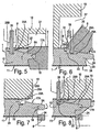
- mechanical tools 6, such as milling cutters As represented in figures 3 to 5 , herein the panels 1 are moved with the guiding groove 22 over guiding portions 26, in this case in the form of a guiding knife, with the purpose of guiding the panels 1 during the formation of at least a portion of the profiled edge regions 5A-5B.
- Figure 4 shows that by means of a rough milling cutter 6 part of the top layer 15 and of the core 12 is removed.
- Figure 15 shows how the tongue 18 substantially is formed. This figure shows that in some cases it is necessary to provide a recess 27 in a shoe 10, such that the respective mechanical tool 6 can rotate freely.
- the panels 1 are moved over at least two guiding portions 26, which together form the guiding knife, between which, at least over the height of the guiding groove 22, a gap 28 is present.
- the gap 28 allows for that, as represented in figure 6 , one of the aforementioned cutting tools 6 can be placed in this gap in order to perform a milling treatment up to the guiding groove 22.
- the represented milling treatment relates to the forming of the lower side of the tongue 18.
- This milling treatment forms, amongst others, a locking part 29A at the panels 1 that allows that two of the finally realized floor panels 1, in coupled condition, are locked in horizontal direction.
- a portion of the actual coupling parts 17A is formed, as simultaneously a material portion is removed that extends up to at least the location where the guiding groove 22 is formed.
- Figure 7 shows the finishing treatment that forms the upper edge 24 of the panel 1.
- the guiding portions 26 herein are no longer active at the height of the location where this finishing treatment takes place, however, it is clear that according to a variant such guiding portion 26 might also be continued up to that point.
- Figure 8 shows a variant of a method according to the first aspect of the present invention.
- the aforementioned finishing treatment takes place after a rough-machining treatment, such as the one of figure 4 .
- treatments may follow as those described in respect to figures 5 and 6 .
- the particularity of this embodiment is that also at the height of the finishing treatment, the guiding portion 26 is situated in the guiding groove 22, which enables a precise edge treatment.
- the guiding portion 26 is situated in the guiding groove 22, which enables a precise edge treatment.
- the precision is particularly important in this finishing treatment, as this determines the final dimensions of the floor panels 1.
- the aforementioned shoes 10 preferably are moveable independently from the guiding portions 26 and that more preferably the guiding portions 26 are fixedly connected to a frame of the processing machine or continuous machine 2.
- Figure 9 represents two floor panels 1 in a coupled condition, which are manufactured by means of a method according to the invention.
- the guiding groove 22 and the profiled edge regions 5A-5B are performed such that the guiding groove 22, in a coupled condition of two of such floor panels 1, is at least partially covered by a material portion 30.
- the aforementioned material portion 30 is formed by a portion of the lower lip 20 of the groove 19.
- the profiled edge regions 5A-5B of the floor panels 1 from the example of figure 9 comprise coupling parts 17A-17B, which are performed with locking parts 29A-29B that engage behind each other and in this manner perform a locking in horizontal direction.
- the locking part 29B is situated in a portion of the lower lip 20 that extends beyond the upper lip 21.
- the aforementioned material portion 30 that partially covers the guiding groove 22, is situated in the portion of the lower lip 20 that extends beyond the upper lip 21.
- the respective locking part 29B is partially situated in the guiding groove 22, or at least in a space 31 that originally formed part of the guiding groove 22.
- Figure 10 shows a variant, wherein, in the represented coupled condition, the guiding groove 22 is largely covered by a material portion 30, in this case a material portion 30 that is situated in the lower lip 20.
- the represented floor panels are also provided with a bevelled edge 32 at their upper side 24, which bevelled edge is obtained by removing a material portion at the respective upper side 24 and the subsequent covering thereof with a decorative layer 33.
- Figure 11 shows a floor panel 1 that is obtained according to a variant of of the invention.
- the guiding groove 22 comprises two substantially parallel sides, flanks or flank portions 25A-25B, which are not vertical.
- one of these flanks 25A forms a locking part 29A at the edge of the floor panel 1 where the tongue 18 is realized.
- This locking part 29A cooperates with the locking part 29B, which is situated in the lower lip 20, and herein has a contact surface 34 that coincides with one of said flanks 29A.
- the represented floor panels comprise a guiding groove 22 with two substantially parallel and substantially vertical flanks 25A-25B, where one of these flanks 25A also forms a locking part 29A at the edge of the floor panel 1 where the tongue 18 is realized.
- Figure 13 represents a floor panel 1 that is obtained according to a variant that does not form part of the present invention.
- the profiled edge region 5B which extends at the lower side 9 of the panel 1 at least up to the guiding groove 22, is realized at the side 3B-4B of the panel 1 at which the groove 19 is formed.
- this method is particularly advantageous where a certain flexibility is expected from the lower lip 20, as this is the case, for example, with some so-called "snap-on connections", wherein during connecting two of such floor panels 1 a bending of this lower lip 20 is required.
- this method can promote or even determine this required flexibility of the lower lip 20 in thicker, for example, solid wooden floor panels 1.
- the guiding groove 22 is provided at such a distance from the upper edge 24 of the floor panels 1, that it is situated at least partially, and still better entirely, in that portion of the lower lip 20 that extends below the upper lip 21.
- Figure 14 represents two more floor panels 1 in a coupled condition, which are obtained, invention by applying a method according to the invention.
- the respective floor panels 1 comprise coupling parts 17A-17B, which are performed substantially in the form of a tongue 18 and a groove 19. In this case, the upper lip 21 and the lower lip 20 that limit the groove 19 are almost equally long.
- a variant of the invention consists in that, when realizing the panels, at least two guiding grooves are employed, which preferably are utilized alternate, more particularly successively.
- the advantage is created that a better guiding can be provided, as, when one of the guiding grooves can not be utilized or is no longer available, then a guiding by means of the other guiding groove can be provided.
- These guiding grooves may be situated both at lower side of the panel, but may also be present at the upper side, lower side, respectively, of such panel.
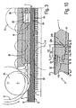
- FIGS 15 and 16 represent a method showing, amongst others, the characteristics of the aforementioned first particular embodiment of the invention.
- panels 1 are transported through a processing machine or continuous machine 2 by means of a first mechanical carrier element 77 and a second mechanical carrier element 78.
- both mechanical elements 77-78 at the height of these contact surfaces 74, are freely movable in a direction transverse to the respective flat panel side 9-11 and can both carrier elements 77-78 adapt themselves in the aforementioned direction to the location of each floor panel 1. So, for example, does the mobility of both carrier elements in the arrangement of the example allow that also the, seen in transfer direction, second floor panel 1 that adopts another location at the height of the carrier elements, can be transported smoothly, as the carrier elements adapt themselves in such a manner that the contacts 79 still can be formed.
- the respective panel 1 has a bending K, as a result of which it takes another location at the height of the carrier elements 77-78.
- this panel 1 by applying a method according to said first particular embodiment, without a problem still can be provided with profiled edge regions 5A-5B.
- the mobility of the mechanical carrier elements 77 and 78, namely, is such that they allow to form the contacts 79 with the respective panel sides 9 and 11 over a distance that is larger than the bending K, measured at the height of these contact surfaces 79.
- both mechanical elements 77-78 comprise belts 8, which, by means of travel wheels 80, are pressed into the direction of said flat panel sides 9 and 11. It is clear that such pressing-on can be realized in various manners. So, for example, may the travel wheels 80 be performed as pressing rollers that are borne in elements, wherein a spring system provides for that these elements, with the pressing rollers borne therein, are pressed against the respective side of the elements 77-78.
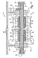
- the panels 1, as is evident from figure 17 are provided with a guiding groove 22, that the panels 1 are guided by means of a guiding portion 26 that engages in this guiding groove 26 and that, while the panels 1 are transported through the processing machine 2, they are pressed, in the immediate proximity of their edge regions 5A-5B to be profiled, onto a sliding shoe 81.
- the two pressure shoes 10 can be moved independently from the guiding portion 26.
- the guiding portion 26 is fixedly installed in respect to the frame 83 of the processing machine 2.
- the method according to the present invention does not exclude that, when forming the aforementioned profiled edge regions 5A-5B, use is made of a processing machine, of which the aforementioned first mechanical element 77 comprises a belt 8 and the second mechanical element 78 comprises a conveyor chain 84.
- a processing machine of which the aforementioned first mechanical element 77 comprises a belt 8 and the second mechanical element 78 comprises a conveyor chain 84.
- such conveyor chain 84 consists of links 85 that are connected to each other by means of hinges 86.
- the chain is reversed over minimum 2 return wheels 87 and, over a part of its path, is transported along a guiding element 88.
- the guiding element 88 supports the chain over its entire length.
- a fixedly installed guiding portion 26 is employed. This offers particular advantages when realizing profiled edge regions 5A-5B. Employing a fixedly installed guiding portion 26 in fact minimizes the influence of possible vibrations of the chain onto the panel 1 or generally offers a more stable transport and/or processing of the panels 1.
- the method comprises at least the following steps:
- the processing machine 2 shall preferably also be provided with additional means that minimize the risk of possible vibrations in the chain and/or enhance the stability of the transport or the treatments. Such vibrations or instabilities, namely, may lead to an inferior processing quality.
- the technique where the conveyor chain 84 is pressed upon the guiding element 88 by means of an attraction force the risk of vibrations occurring due to upsetting of the conveyor chain 84 is minimized.
- attraction force can be realized in any manner by creating magnetic attraction forces or pressing forces between, on the one hand, certain parts of the conveyor chain 84, and, on the other hand, certain parts of the guiding element 88.
- the magnetic attraction takes place at guiding elements 88, or portions thereof that are situated at locations where the conveyor chain 84 runs onto the return wheels 87, leave these, respectively. It is, however, clear that the attraction can also be realized at other locations, for example, at the location of the guide 89 and/or at the location of the circumference of the return wheels 87.
- the second technique when employing the second technique, in other words, the technique where the polygon effect in the conveyor chain 84 is minimized, also the occurrence of vibrations in the conveyor chain 84 is minimized.
- the polygon effect occurs there, where the conveyor chain 84 is reversed over the return wheels 87.
- the conveyor chain 84 bends irregularly when reversing. This irregular reversion results in speed variations of the conveyor chain 84 and vibrations that can continue into other parts of the processing machine 2.
- Compensating polygon effects in a conveyor chain is a technique that is known as such, in which respect reference is made to EP 1 304 302 , however, the combination of this technique with the other techniques of the thirteenth aspect as such is novel and inventive.
- the guiding portion 26 is fixedly installed, more particularly rigidly connected to a frame 83 of the processing machine. This arrangement allows a very stable transport of the panels 1 and a correspondingly high quality of the treatments in the machine 2.
- the application of the aforementioned second technique namely, the application of means in order to minimize the polygon effect
- the aforementioned first technique namely, employing a conveyor chain 84, which, by magnetic attraction, is retained on a guiding element 88.
- the aforementioned guiding element 88, over which the conveyor chain 84 is running is provided with a portion that subjects the conveyor chain 84 to a gradual transition movement towards and/or from the return wheel 87, such that the mutual bending of the links 85 during reversing of the conveyor chain 84 occurs more gradually.
Landscapes
- Engineering & Computer Science (AREA)
- Life Sciences & Earth Sciences (AREA)
- Mechanical Engineering (AREA)
- Architecture (AREA)
- General Engineering & Computer Science (AREA)
- Wood Science & Technology (AREA)
- Forests & Forestry (AREA)
- Structural Engineering (AREA)
- Civil Engineering (AREA)
- Floor Finish (AREA)
- Physics & Mathematics (AREA)
- Electromagnetism (AREA)
- Steam Or Hot-Water Central Heating Systems (AREA)
- Processing Of Solid Wastes (AREA)
- Laminated Bodies (AREA)
- Panels For Use In Building Construction (AREA)
- Conveying And Assembling Of Building Elements In Situ (AREA)
Claims (14)
- Procédé de fabrication pour des panneaux de sol, dans lequel on part de panneaux (1), ces panneaux (1), sur leur côté inférieur (9), étant munis d'au moins une rainure de guidage (22), et ces panneaux (1), au moins à deux côtés opposés (3A-3B ; 4A-4B), étant munis de zones marginales profilées (5A-5B) qui comprennent des éléments d'accouplement (17A-17B), essentiellement sous la forme d'une languette (18) et d'une rainure (19), cette dernière étant limitée au moyen d'une lèvre inférieure (20) et d'une lèvre supérieure (21), caractérisé en ce que les éléments d'accouplement susmentionnés (17A-17B) sont réalisés avec des éléments de verrouillage (29A-29B), de telle sorte que, à l'état accouplé d'au moins deux desdits panneaux de sol (1), on obtient un verrouillage réciproque aussi bien en direction horizontale qu'en direction verticale, dans lequel lesdits panneaux de sol possèdent une épaisseur entre 5 et 15 mm et au moins une des deux zones marginales profilées susmentionnées (5A-5B) est réalisée de telle sorte que cette zone, vu dans la section transversale du panneau (1), en direction transversale par rapport à la rainure de guidage (22) s'étend, du côté inférieur (9) du panneau (1), au moins jusqu'à la rainure de guidage (22), et ladite rainure de guidage (22) est réalisée du côté (3A-4A) du panneau (1) sur lequel est formée la languette susmentionnée (18).
- Procédé selon la revendication 1, caractérisé en ce que la rainure de guidage (22) et les zones marginales profilées (5A-5B) sont réalisées de telle sorte que la rainure de guidage (22), à l'état accouplé de deux panneaux de sol de ce type (1), est recouverte au moins en partie par une portion de matière (30).
- Procédé selon la revendication 2, caractérisé en ce que la portion de matière susmentionnée (30) qui recouvre la rainure de guidage (22) au moins en partie est formée par une portion de la lèvre inférieure (20).
- Procédé selon la revendication 2 ou 3, caractérisé en ce que la lèvre inférieure susmentionnée (20) possède une portion qui s'étend au-delà de la lèvre supérieure (21) ; en ce que les éléments de verrouillage (29A-29B) comprennent des portions qui viennent s'engrener l'une derrière l'autre et de cette manière réalisent un verrouillage en direction horizontale ; en ce qu'un de ces éléments de verrouillage (29B) est situé dans la portion de la lèvre inférieure (20) qui s'étend au-delà de la lèvre supérieure (21) ; et en ce que la portion de matière susmentionnée (30) est également située dans la portion de la lèvre inférieure (20) qui s'étend au-delà de la lèvre supérieure (21).
- Procédé selon la revendication 4, caractérisé en ce que l'élément de verrouillage susmentionné (29B) qui est situé à la lèvre inférieure (20), à l'état accouplé de deux panneaux de sol de ce type (1), est situé au moins en partie dans la rainure de guidage (22) ou au moins dans un espace (31) qui fait partie à l'origine de la rainure de guidage (22).
- Procédé selon l'une quelconque des revendications précédentes, caractérisé en ce que la rainure de guidage susmentionnée (22) est appliquée, au moins pour guider les panneaux (1), au moins au cours de la formation d'au moins une portion des zones marginales profilées (5A-5B), les panneaux (1), à cet effet, étant déplacés avec la rainure de guidage (22) par-dessus une ou plusieurs portions de guidage (26).
- Procédé selon la revendication 6, caractérisé en ce que les panneaux (1) sont déplacés par-dessus au moins deux portions de guidage (26), entre lesquelles, au moins sur la hauteur de la rainure de guidage (22), est présent un espace libre (28), un ou plusieurs outils de traitement (6) et/ou outils auxiliaires (10) pour la formation d'au moins une portion de la région marginale profilée respective (5A-5B) étant actifs dans ledit espace libre (28).
- Procédé selon la revendication 6 ou 7, caractérisé en ce que la rainure de guidage susmentionnée (22) est appliquée au moins pour guider les panneaux (1) au cours de la réalisation des éléments d'accouplement susmentionnés (17A-17B).
- Procédé selon l'une quelconque des revendications précédentes, caractérisé en ce que la rainure de guidage (22), mesurée en direction horizontale, est située à une distance, par rapport au plan vertical (V) dans lequel se rejoignent les panneaux de sol accouplés (1) avec leur côté supérieur (24) l'un contre l'autre, telle que l'on satisfait à un des deux critères suivants ou aux deux :- la distance (D1) entre le plan vertical susmentionné (V) et le côté (25A) le plus proche de la rainure de guidage (22) est supérieure à 3 mm ;- la distance (D2) entre le plan vertical susmentionné (V) et le côté (25B) qui en est le plus éloigné est inférieure à 12 mm.
- Procédé selon l'une quelconque des revendications précédentes, caractérisé en ce que, après la formation des zones marginales profilées (5A-5B), au moins un reste de la rainure de guidage susmentionné (22) subsiste, en d'autres termes, au moins deux portions de flancs latéraux (25A-25B) de cette rainure de guidage (22) sont maintenues.
- Procédé selon l'une quelconque des revendications précédentes, caractérisé en ce que, lors de la formation des éléments d'accouplement (17A-17B), et plus particulièrement lors de la formation d'un élément de verrouillage (29A) procurant un verrouillage en direction horizontale, au moyen du même outil (6) une portion des éléments de verrouillage proprement dits (17A) est formée et, de manière simultanée, une portion de matière est retirée, qui s'étend au moins jusqu'à l'endroit où la rainure de guidage (22) est formée ou doit être formée.
- Procédé selon l'une quelconque des revendications précédentes, caractérisé en ce que les panneaux (1) sont transportés à travers une machine de traitement (2) au moyen d'au moins un élément de transport (78) qui est constitué par une chaîne transporteuse (84) ; en ce que lesdites portions marginales profilées (5A-5B) sont réalisées tandis que les panneaux (1), au moyen de la chaîne transporteuse susmentionnée (84), sont transportés à travers la machine de traitement susmentionnée (2) et s'y déplacent avec leurs portions marginales (5A-5B) à profiler le long d'outils de coupe (6) ; en ce que les panneaux (1) sont guidés latéralement au moyen d'une portion de guidage (26) qui vient s'insérer dans ladite rainure de guidage (22), tandis que les panneaux, comme mentionné, sont transportés à travers la machine de traitement (2).
- Procédé selon la revendication 12, caractérisé en ce que la portion de guidage (26) est montée à demeure, plus particulièrement est reliée de manière rigide à un bâti (83) de la machine de traitement (2).
- Procédé selon la revendication 12 ou 13, caractérisé en ce que ladite chaîne transporteuse (84) est formée par des maillons de chaînes et en ce qu'on utilise au moins une des techniques suivantes :- la technique dans laquelle la chaîne transporteuse (84), au moins sur une portion de son parcours, est transportée le long d'un élément de guidage (88) et est comprimée par des forces magnétiques agissant sur l'élément de guidage (88) ;- la technique dans laquelle des moyens sont appliqués pour minimiser l'effet de polygone de la chaîne transporteuse (84).
Priority Applications (4)
| Application Number | Priority Date | Filing Date | Title |
|---|---|---|---|
| EP10075493A EP2298516A3 (fr) | 2005-03-31 | 2006-03-28 | Procédé de fabrication des panneaux de plancher et panneau de plancher |
| EP08075858A EP2030746A1 (fr) | 2005-03-31 | 2006-03-28 | Procédé de fabrication et d'emballage de panneaux de plancher, dispositifs utilisés correspondants, et panneau de plancher et ensemble emballé de panneaux de plancher |
| PL06727536T PL1890853T3 (pl) | 2005-03-31 | 2006-03-28 | Sposób wytwarzania paneli podłogowych |
| EP09075312A EP2108492B1 (fr) | 2005-03-31 | 2006-03-28 | Procédé de fabrication de panneaux de plancher |
Applications Claiming Priority (4)
| Application Number | Priority Date | Filing Date | Title |
|---|---|---|---|
| BE2005/0169A BE1016561A6 (nl) | 2005-03-31 | 2005-03-31 | Werkwijzen voor het vervaardigen en verpakken van vloerpanelen, alsmede vloerpaneel en verpakte set van vloerpanelen. |
| US67253805P | 2005-04-19 | 2005-04-19 | |
| BE2006/0024A BE1016938A6 (nl) | 2005-03-31 | 2006-01-12 | Werkwijzen voor het vervaardigen en verpakken van vloerpanelen, inrichtingen hierbij aangewend, alsmede vloerpaneel en verpakte set van vloerpanelen. |
| PCT/IB2006/000993 WO2006103565A2 (fr) | 2005-03-31 | 2006-03-28 | Procedes de fabrication et de conditionnement de panneaux de plancher, dispositifs utilises a cet effet et panneau de plancher et ensemble conditionne de panneaux de plancher |
Related Child Applications (1)
| Application Number | Title | Priority Date | Filing Date |
|---|---|---|---|
| EP08075858A Division EP2030746A1 (fr) | 2005-03-31 | 2006-03-28 | Procédé de fabrication et d'emballage de panneaux de plancher, dispositifs utilisés correspondants, et panneau de plancher et ensemble emballé de panneaux de plancher |
Publications (2)
| Publication Number | Publication Date |
|---|---|
| EP1890853A2 EP1890853A2 (fr) | 2008-02-27 |
| EP1890853B1 true EP1890853B1 (fr) | 2009-01-21 |
Family
ID=38543904
Family Applications (4)
| Application Number | Title | Priority Date | Filing Date |
|---|---|---|---|
| EP06727536A Expired - Lifetime EP1890853B1 (fr) | 2005-03-31 | 2006-03-28 | Procede de fabrication de panneaux de plancher |
| EP08075858A Withdrawn EP2030746A1 (fr) | 2005-03-31 | 2006-03-28 | Procédé de fabrication et d'emballage de panneaux de plancher, dispositifs utilisés correspondants, et panneau de plancher et ensemble emballé de panneaux de plancher |
| EP09075312A Expired - Lifetime EP2108492B1 (fr) | 2005-03-31 | 2006-03-28 | Procédé de fabrication de panneaux de plancher |
| EP10075493A Withdrawn EP2298516A3 (fr) | 2005-03-31 | 2006-03-28 | Procédé de fabrication des panneaux de plancher et panneau de plancher |
Family Applications After (3)
| Application Number | Title | Priority Date | Filing Date |
|---|---|---|---|
| EP08075858A Withdrawn EP2030746A1 (fr) | 2005-03-31 | 2006-03-28 | Procédé de fabrication et d'emballage de panneaux de plancher, dispositifs utilisés correspondants, et panneau de plancher et ensemble emballé de panneaux de plancher |
| EP09075312A Expired - Lifetime EP2108492B1 (fr) | 2005-03-31 | 2006-03-28 | Procédé de fabrication de panneaux de plancher |
| EP10075493A Withdrawn EP2298516A3 (fr) | 2005-03-31 | 2006-03-28 | Procédé de fabrication des panneaux de plancher et panneau de plancher |
Country Status (8)
| Country | Link |
|---|---|
| US (4) | US8161701B2 (fr) |
| EP (4) | EP1890853B1 (fr) |
| AT (2) | ATE421414T1 (fr) |
| BE (1) | BE1016938A6 (fr) |
| DE (2) | DE602006004992D1 (fr) |
| ES (1) | ES2321445T3 (fr) |
| PL (1) | PL1890853T3 (fr) |
| WO (1) | WO2006103565A2 (fr) |
Cited By (1)
| Publication number | Priority date | Publication date | Assignee | Title |
|---|---|---|---|---|
| RU2470794C2 (ru) * | 2009-12-23 | 2012-12-27 | Флоринг Текнолоджиз Лтд. | Способ и устройство для облагораживания древесно-стружечной плиты |
Families Citing this family (74)
| Publication number | Priority date | Publication date | Assignee | Title |
|---|---|---|---|---|
| SE517478C2 (sv) * | 1999-04-30 | 2002-06-11 | Valinge Aluminium Ab | Låssystem för mekanisk hofogning av golvskivor, golvskiva försedd med låssystemet samt metod för framställning av mekaniskt hopfogningsbara golvskivor |
| US20130139478A1 (en) | 2005-03-31 | 2013-06-06 | Flooring Industries Limited, Sarl | Methods for packaging floor panels, as well as packed set of floor panels |
| BE1016938A6 (nl) | 2005-03-31 | 2007-10-02 | Flooring Ind Ltd | Werkwijzen voor het vervaardigen en verpakken van vloerpanelen, inrichtingen hierbij aangewend, alsmede vloerpaneel en verpakte set van vloerpanelen. |
| BE1016846A3 (nl) | 2005-11-09 | 2007-08-07 | Flooring Ind Ltd | Vloerbekleding, vloerpanelen en werkwijze voor het vervaardigen van vloerpanelen. |
| WO2007106352A2 (fr) * | 2006-03-10 | 2007-09-20 | Mannington Mills, Inc. | Procédé et système permettant de subdiviser un substrat de parquet contre-collé |
| BE1017157A3 (nl) | 2006-06-02 | 2008-03-04 | Flooring Ind Ltd | Vloerbekleding, vloerelement en werkwijze voor het vervaardigen van vloerelementen. |
| DE102007035235A1 (de) | 2007-07-27 | 2009-01-29 | Wemhöner Anlagen GmbH & Co. KG | Verbesserung der Führung von Werkstücken in Bearbeitungsmaschinen zum Bearbeiten von plattenförmigen Körpern für die Holz- und Baustoffindustrie |
| US8353140B2 (en) * | 2007-11-07 | 2013-01-15 | Valinge Innovation Ab | Mechanical locking of floor panels with vertical snap folding |
| US8499521B2 (en) | 2007-11-07 | 2013-08-06 | Valinge Innovation Ab | Mechanical locking of floor panels with vertical snap folding and an installation method to connect such panels |
| EP2163362A1 (fr) * | 2008-09-15 | 2010-03-17 | Spanolux N.V. Div. Balterio | Procédé et appareil pour la fabrication d'une pièce de panneau courte |
| NL2003699A (en) | 2008-12-18 | 2010-06-21 | Brion Tech Inc | Method and system for lithography process-window-maximixing optical proximity correction. |
| EP2391488A4 (fr) * | 2009-01-30 | 2015-05-13 | René St Cyr 1996 Inc | Fabrication de profils à languette et rainure sur des lames de parquet en bois dur |
| KR101675397B1 (ko) | 2009-07-31 | 2016-11-11 | 뵈린게 이노베이션 에이비이 | 빌딩 패널의 에지 기계가공에 관한 방법 및 장치 |
| CA2764965C (fr) | 2009-07-31 | 2017-10-03 | Vaelinge Innovation Ab | Procedes et agencements concernant l'usinage de bord de panneaux de construction |
| US11717901B2 (en) | 2009-07-31 | 2023-08-08 | Valinge Innovation Ab | Methods and arrangements relating to edge machining of building panels |
| ES2734439T3 (es) | 2009-12-22 | 2019-12-05 | Flooring Ind Ltd Sarl | Método para producir paneles de revestimiento |
| DE102010019567A1 (de) | 2010-05-05 | 2011-11-10 | Fritz Egger Gmbh & Co. Og | Paneel, insbesondere Fußbodenpaneel mit abgeschrägten Kanten und Verfahren zur Herstellung solcher Paneele |
| BE1019501A5 (nl) | 2010-05-10 | 2012-08-07 | Flooring Ind Ltd Sarl | Vloerpaneel en werkwijze voor het vervaardigen van vloerpanelen. |
| US8925275B2 (en) | 2010-05-10 | 2015-01-06 | Flooring Industries Limited, Sarl | Floor panel |
| BE1019331A5 (nl) | 2010-05-10 | 2012-06-05 | Flooring Ind Ltd Sarl | Vloerpaneel en werkwijzen voor het vervaardigen van vloerpanelen. |
| US9695600B2 (en) * | 2011-10-03 | 2017-07-04 | Unilin Bvba | Panel and method for manufacturing panels |
| EP2586718B1 (fr) * | 2011-10-31 | 2014-05-28 | Tetra Laval Holdings & Finance S.A. | Unité de pliage de production de paquets pliés de produits alimentaires pouvant être versés à partir de paquets scellés relatifs |
| BE1020305A5 (nl) * | 2011-12-05 | 2013-07-02 | Unilin Bvba | Verpakte set panelen. |
| EP3238899B1 (fr) | 2012-06-19 | 2020-09-02 | Välinge Innovation AB | Système de verrouillage mécanique pour planchers |
| WO2014033628A1 (fr) | 2012-08-27 | 2014-03-06 | Pergo (Europe) Ab | Panneau |
| US20140102590A1 (en) * | 2012-10-16 | 2014-04-17 | Michael Towey | Monocoque furniture assembly and method of manufacture |
| BE1021497B1 (nl) | 2012-11-20 | 2015-12-03 | Unilin Bvba | Verpakte set panelen |
| WO2015104680A1 (fr) * | 2014-01-09 | 2015-07-16 | Flooring Industries Limited, Sarl | Panneau de plancher destiné à la formation d'un revêtement de plancher |
| WO2015183248A1 (fr) * | 2014-05-28 | 2015-12-03 | The Boeing Company | Assemblages de panneau sandwich et procédés d'assemblage de panneaux sandwich |
| BE1021929B1 (nl) | 2014-07-04 | 2016-01-27 | Unilin Bvba | Vloerpaneel |
| HUE061045T2 (hu) * | 2014-08-29 | 2023-05-28 | Vaelinge Innovation Ab | Függõleges illesztékrendszer felületburkoló panelhez |
| DE102014116781A1 (de) * | 2014-10-10 | 2016-04-14 | Hamberger Industriewerke Gmbh | Doppelendprofiler |
| DE102015005864A1 (de) * | 2015-05-11 | 2016-11-17 | Fritz Egger Gmbh & Co. Og | Verfahren zur Herstellung von Vertiefungen aufweisenden Paneelen |
| DE102015008891B3 (de) * | 2015-07-09 | 2016-08-25 | Ima Klessmann Gmbh Holzbearbeitungssysteme | Verfahren und Vorrichtung zur Kantendickenmessung beim Aufbringen von Kantenkaschierung auf die Schmalseiten plattenförmiger Werkstücke |
| DE102016001995A1 (de) | 2016-02-19 | 2017-08-24 | Siempelkamp Logistics & Service GmbH | Vorrichtung und Verfahren zum Beschneiden und Vermessen einer Platte |
| EP3309323A1 (fr) * | 2016-10-11 | 2018-04-18 | Franz Eschlbeck | Panneau et connexion de panneau |
| BE1024734B1 (nl) | 2016-11-10 | 2018-06-19 | Ivc Bvba | Vloerpaneel en werkwijze voor het vervaardigen van een vloerpaneel |
| DE102017002271A1 (de) | 2017-03-09 | 2018-09-13 | Ima Klessmann Gmbh Holzbearbeitungssysteme | Verfahren zum Aufteilen eines plattenförmigen Werkstücks |
| DE102017106329A1 (de) | 2017-03-23 | 2018-09-27 | Guido Schulte | Bearbeitungsanlage für plattenförmige Werkstücke |
| WO2019003100A1 (fr) * | 2017-06-27 | 2019-01-03 | Flooring Industries Limited, Sarl | Panneau mural ou de plafond et ensemble mur ou plafond |
| US12234654B2 (en) | 2017-08-15 | 2025-02-25 | National Nail Corp. | Hidden fastener unit and related method of use |
| US11111679B2 (en) | 2017-08-15 | 2021-09-07 | National Nail Corp. | Hidden fastener unit and related method of use |
| US11898357B2 (en) | 2017-08-15 | 2024-02-13 | National Nail Corp. | Hidden fastener unit and related method of use |
| US11261893B2 (en) | 2017-08-15 | 2022-03-01 | National Nail Corp. | Hidden fastener unit and related method of use |
| USD1019365S1 (en) | 2023-05-31 | 2024-03-26 | National Nail Corp. | Fastener positioning device |
| US11149445B2 (en) | 2017-08-15 | 2021-10-19 | National Nail Corp. | Hidden fastener unit and related method of use |
| US10378218B2 (en) | 2017-08-15 | 2019-08-13 | National Nail Corp. | Hidden fastener unit and related method of use |
| USD853829S1 (en) | 2018-06-01 | 2019-07-16 | National Nail Corp. | Fastener positioning device |
| USD924044S1 (en) | 2019-11-20 | 2021-07-06 | National Nail Corp. | Fastener positioning device |
| USD850897S1 (en) | 2018-05-18 | 2019-06-11 | National Nail Corp. | Fastener positioning device |
| USD945870S1 (en) | 2020-11-17 | 2022-03-15 | National Nail Corp. | Fastener positioning device |
| EP4524345A3 (fr) | 2018-01-10 | 2025-05-28 | Välinge Innovation AB | Joint de sous-plancher |
| BE1026099B1 (nl) | 2018-03-16 | 2019-10-14 | Kreafin Group Sa | Paneel waarvan de koppelmiddelen geschikt zijn om de langse zijden en/of kopse zijden onderling met elkaar te verbinden |
| WO2020025129A1 (fr) | 2018-08-01 | 2020-02-06 | Xylo Technologies Ag | Procédé de fabrication de panneaux à partir d'une planche, plaque de presse, procédé de fabrication d'une planche et planche |
| US11578495B2 (en) | 2018-12-05 | 2023-02-14 | Valinge Innovation Ab | Subfloor joint |
| USD850898S1 (en) | 2019-01-07 | 2019-06-11 | National Nail Corp. | Fastener positioning device |
| BE1027083B1 (nl) | 2019-02-26 | 2020-09-24 | Flooring Ind Ltd Sarl | Glij- of drukschoen voor een doorloopfreesmachine en werkwijze voor het vervaardigen van panelen |
| US11712816B2 (en) * | 2019-03-05 | 2023-08-01 | Ceraloc Innovation Ab | Method and system for forming grooves in a board element and an associated panel |
| CN109968432B (zh) * | 2019-03-28 | 2023-05-26 | 豪德机械(上海)有限公司 | 一种地板背部开槽设备 |
| CN109794978B (zh) * | 2019-03-28 | 2023-05-26 | 豪德机械(上海)有限公司 | 一种带吸尘处理的地板背部开槽设备 |
| DE202019101807U1 (de) | 2019-03-29 | 2019-05-06 | Akzenta Paneele + Profile Gmbh | Paneel |
| EP3798385A1 (fr) | 2019-09-24 | 2021-03-31 | Välinge Innovation AB | Panneau de construction |
| US20210114250A1 (en) * | 2019-10-18 | 2021-04-22 | Jeff Chandler | Method and apparatus for reducing loss due to chipout |
| BE1027883B1 (nl) | 2019-12-18 | 2021-07-27 | Unilin Bv | Werkwijze voor het vervaardigen van panelen |
| BE1028185B1 (nl) | 2020-04-03 | 2021-11-04 | Flooring Ind Ltd Sarl | Paneel |
| US11731252B2 (en) | 2021-01-29 | 2023-08-22 | National Nail Corp. | Screw guide and related method of use |
| NO20220456A1 (en) * | 2022-04-22 | 2023-10-23 | Beaulieu Int Group Nv | Method for manufacturing a wood-topped covering panel with a bevelled edge |
| BE1030681B1 (nl) | 2022-07-01 | 2024-01-29 | Flooring Ind Ltd Sarl | Set van freeswerktuigen en werkwijze voor het vervaardigen van panelen |
| WO2024013623A1 (fr) | 2022-07-14 | 2024-01-18 | Flooring Industries Limited, Sarl | Procédé de fabrication de panneaux et panneaux obtenus par celui-ci |
| US12297649B2 (en) | 2022-10-27 | 2025-05-13 | Primesource Building Products, Inc. | Deck clip |
| BE1031131B1 (nl) | 2022-12-13 | 2024-07-10 | Unilin Bv | Werkwijze voor het vervaardigen van panelen |
| USD1022684S1 (en) | 2023-02-23 | 2024-04-16 | National Nail Corp. | Fastener positioning device |
| BE1031867B1 (nl) | 2023-08-04 | 2025-03-04 | Unilin Bv | Werkwijze voor het vervaardigen van panelen |
| WO2026003675A1 (fr) | 2024-06-26 | 2026-01-02 | Aladdin Manufacturing Corporation | Endos de tapis fabriqué à partir d'articles à surface souple recyclés |
Citations (2)
| Publication number | Priority date | Publication date | Assignee | Title |
|---|---|---|---|---|
| DE202004018661U1 (de) * | 2004-11-13 | 2005-02-17 | Torwegge Holzbearbeitungsmaschinen Gmbh | Doppelendprofiler mit Werkstück-Führungsschiene |
| WO2005068747A1 (fr) * | 2004-01-13 | 2005-07-28 | Välinge Innovation AB | Systeme de couverture et de blocage de parquets et equipement de production de lames de parquet, par exemple. |
Family Cites Families (276)
| Publication number | Priority date | Publication date | Assignee | Title |
|---|---|---|---|---|
| US124228A (en) | 1872-03-05 | Improvement in skate-fastenings | ||
| US1194636A (en) | 1916-08-15 | Silent door latch | ||
| US2732706A (en) | 1956-01-31 | Friedman | ||
| US753791A (en) | 1903-08-25 | 1904-03-01 | Elisha J Fulghum | Method of making floor-boards. |
| US1331018A (en) | 1919-09-29 | 1920-02-17 | Joseph O Luthy | Separator for secondary batteries |
| SE57493C1 (fr) | 1923-10-01 | 1924-09-16 | ||
| US1743492A (en) | 1927-08-02 | 1930-01-14 | Harry E Sipe | Resilient plug, dowel, and coupling pin |
| US1723306A (en) | 1927-08-02 | 1929-08-06 | Harry E Sipe | Resilient attaching strip |
| US1809393A (en) | 1929-05-09 | 1931-06-09 | Byrd C Rockwell | Inlay floor construction |
| US1802514A (en) * | 1929-06-10 | 1931-04-28 | Arthur B Johnson | Sawing machine |
| US1859667A (en) * | 1930-05-14 | 1932-05-24 | J K Gruner Lumber Company | Jointed lumber |
| US1902716A (en) | 1931-09-08 | 1933-03-21 | Midland Creosoting Company | Flooring |
| US2026511A (en) | 1934-05-14 | 1935-12-31 | Storm George Freeman | Floor and process of laying the same |
| US2184113A (en) | 1935-03-05 | 1939-12-19 | Annunziata Calafati | Building construction |
| US2204675A (en) | 1937-09-29 | 1940-06-18 | Frank A Grunert | Flooring |
| US2596280A (en) | 1947-03-21 | 1952-05-13 | Standard Railway Equipment Mfg | Metal covered walls |
| US2666233A (en) | 1949-01-12 | 1954-01-19 | Edwin O Klemm | Prefabricated building construction |
| US2517939A (en) | 1949-05-06 | 1950-08-08 | Stewart James Elliott | Lumber package-rescaled, divisional, bound, and protectively covered |
| US2559261A (en) | 1949-10-17 | 1951-07-03 | Michael D Schwartz | Architectural model construction set |
| US2740167A (en) | 1952-09-05 | 1956-04-03 | John C Rowley | Interlocking parquet block |
| US2863185A (en) | 1954-02-16 | 1958-12-09 | Arnold T Riedi | Joint construction including a fastener for securing two structural members together in edge-to-edge closely abutting relation |
| US2865058A (en) | 1955-04-12 | 1958-12-23 | Gustaf Kahr | Composite floors |
| FR1138595A (fr) | 1955-12-15 | 1957-06-17 | Outil pour le travail d'ébauches de talons en bois | |
| US3023681A (en) | 1958-04-21 | 1962-03-06 | Edoco Technical Products | Combined weakened plane joint former and waterstop |
| US3077703A (en) | 1959-04-17 | 1963-02-19 | Wood Conversion Co | Roof deck structure |
| US3177279A (en) | 1961-10-19 | 1965-04-06 | Cavrok Mfg Company | Method of molding a decorative building panel |
| US3350827A (en) | 1964-01-02 | 1967-11-07 | Ridge Rock Ind Inc | Building panels and method of mounting the panels |
| US3271787A (en) | 1964-04-06 | 1966-09-13 | Arthur L Clary | Resilient swimming pool coping |
| US3325585A (en) | 1966-03-15 | 1967-06-13 | John H Brenneman | Combined panel fastener and electrical conduit |
| US3396640A (en) | 1966-04-25 | 1968-08-13 | Grace W R & Co | Joint sealing devices |
| US3378958A (en) | 1966-09-21 | 1968-04-23 | Goodrich Co B F | Extrusions having integral portions of different stiffness |
| US3387422A (en) * | 1966-10-28 | 1968-06-11 | Bright Brooks Lumber Company O | Floor construction |
| GB1171337A (en) | 1967-01-28 | 1969-11-19 | Transitoria Trading Company Ab | A Latching Means for Cupboard Doors, Locker Doors, Drawers and like Openable Members |
| US3512324A (en) | 1968-04-22 | 1970-05-19 | Lola L Reed | Portable sectional floor |
| US3594979A (en) | 1968-07-15 | 1971-07-27 | Abitibi Corp | Automatic board wrapping machine |
| US3517927A (en) | 1968-07-24 | 1970-06-30 | William Kennel | Helical spring bouncing device |
| US3572224A (en) | 1968-10-14 | 1971-03-23 | Kaiser Aluminium Chem Corp | Load supporting plank system |
| US3579941A (en) * | 1968-11-19 | 1971-05-25 | Howard C Tibbals | Wood parquet block flooring unit |
| US3526071A (en) | 1969-02-17 | 1970-09-01 | Kogyo Gomu Co Ltd | Panel for curtain walls and method of jointing corners of the same |
| SE0002342L (sv) | 2000-06-22 | 2001-07-16 | Tarkett Sommer Ab | Golvbräda med kopplingsorgan |
| US3760547A (en) | 1969-08-13 | 1973-09-25 | J Brenneman | Spline and seat connector assemblies |
| US3535844A (en) | 1969-10-30 | 1970-10-27 | Glaros Products Inc | Structural panels |
| US3641730A (en) | 1969-12-19 | 1972-02-15 | Alan F Meckstroth | Expandable joint device |
| NL7102276A (fr) | 1970-02-20 | 1971-08-24 | ||
| DE2021503A1 (de) | 1970-05-02 | 1971-11-25 | Freudenberg Carl Fa | Fussbodenplatten und Verfahren zu deren Verbinden |
| DE2111324C3 (de) | 1971-03-10 | 1979-07-05 | Migua-Mitteldeutsche Gummi Und Asbestgesellschaft Hammerschmidt & Co, 5628 Heiligenhaus | Vorrichtung zum Dichten von Fugen zwischen Bauteilen |
| GB1398709A (en) | 1971-07-12 | 1975-06-25 | Bpb Industries Ltd | Building panel |
| DE2238660A1 (de) | 1972-08-05 | 1974-02-07 | Heinrich Hebgen | Formschluessige fugenverbindung von plattenfoermigen bauelementen ohne gesonderte verbindungselemente |
| DE2159042C3 (de) | 1971-11-29 | 1974-04-18 | Heinrich 6700 Ludwigshafen Hebgen | Dämmplatte, insbesondere aus Kunststoffhartschaum |
| US3786608A (en) * | 1972-06-12 | 1974-01-22 | W Boettcher | Flooring sleeper assembly |
| US3778954A (en) | 1972-09-07 | 1973-12-18 | Johns Manville | Method of replacing a damaged bulkhead panel |
| US3835620A (en) | 1973-01-02 | 1974-09-17 | Alcan Aluminum Corp | Apparatus for stacking panels or the like |
| US3919820A (en) | 1973-12-13 | 1975-11-18 | Johns Manville | Wall structure and device for sealing thereof |
| FR2256807A1 (en) | 1974-01-07 | 1975-08-01 | Merzeau Jean Alain | Woodworking tool forming slots - has multiple sets of toothed rotary cutters and spacers altered to vary spacing of slots |
| CA1012731A (en) | 1974-08-30 | 1977-06-28 | Beaconfield Consulting Services Limited | Attaching means for members at an angle to one another |
| AT341738B (de) | 1974-12-24 | 1978-02-27 | Hoesch Werke Ag | Verbundelement mit nut- und federverbindung |
| AR207658A1 (es) | 1975-07-15 | 1976-10-22 | Gen Tire & Rubber Co | Sello elastomerico reforzado y un metodo para fabricarlo |
| US4080086A (en) | 1975-09-24 | 1978-03-21 | Watson-Bowman Associates, Inc. | Roadway joint-sealing apparatus |
| US3980173A (en) * | 1975-10-02 | 1976-09-14 | Owens-Illinois, Inc. | Precision moving platform |
| US4169688A (en) | 1976-03-15 | 1979-10-02 | Sato Toshio | Artificial skating-rink floor |
| US4064571A (en) | 1976-09-13 | 1977-12-27 | Timerax Holdings Ltd. | Pool liner retainer |
| US4082129A (en) | 1976-10-20 | 1978-04-04 | Morelock Donald L | Method and apparatus for shaping and planing boards |
| US4113399A (en) | 1977-03-02 | 1978-09-12 | Hansen Sr Wray C | Knob spring |
| US4107892A (en) | 1977-07-27 | 1978-08-22 | Butler Manufacturing Company | Wall panel unit |
| ES230786Y (es) | 1977-08-27 | 1978-03-16 | Junta para paneles de tejado. | |
| SE407174B (sv) | 1978-06-30 | 1979-03-19 | Bahco Verktyg Ab | Vridande handverktyg med skafthalrum for forvaring av verktygselement |
| DE2828769A1 (de) | 1978-06-30 | 1980-01-03 | Oltmanns Heinrich Fa | Kastenfoermige bautafel aus extrudiertem kunststoff |
| EP0013852A1 (fr) | 1979-01-25 | 1980-08-06 | Claude Delfolie | Porte formée de profilés en résine synthétique légèrement déformables élastiquement |
| US4479333A (en) | 1979-03-05 | 1984-10-30 | Hendrich John H | Folded building module and method of assembly |
| US4426820A (en) | 1979-04-24 | 1984-01-24 | Heinz Terbrack | Panel for a composite surface and a method of assembling same |
| GB2051916A (en) | 1979-05-02 | 1981-01-21 | Ludford D | Structural Panels, Connectors Therefor and a Structure Erected Therefrom |
| US4304083A (en) | 1979-10-23 | 1981-12-08 | H. H. Robertson Company | Anchor element for panel joint |
| US4471012A (en) | 1982-05-19 | 1984-09-11 | Masonite Corporation | Square-edged laminated wood strip or plank materials |
| US4538392A (en) | 1983-02-09 | 1985-09-03 | Horner Flooring Company | Portable sectional flooring system |
| DK149498C (da) | 1983-04-07 | 1986-12-01 | Inter Ikea As | Beklaedning af braedder til f.eks. gulve eller paneler |
| US4512131A (en) | 1983-10-03 | 1985-04-23 | Laramore Larry W | Plank-type building system |
| DE3343601C2 (de) | 1983-12-02 | 1987-02-12 | Bütec Gesellschaft für bühnentechnische Einrichtungen mbH, 4010 Hilden | Entfernbarer Bodenbelag |
| US4648165A (en) | 1984-11-09 | 1987-03-10 | Whitehorne Gary R | Metal frame (spring puller) |
| US4819932A (en) | 1986-02-28 | 1989-04-11 | Trotter Jr Phil | Aerobic exercise floor system |
| US5135597A (en) | 1988-06-23 | 1992-08-04 | Weyerhaeuser Company | Process for remanufacturing wood boards |
| US5007222A (en) | 1988-11-14 | 1991-04-16 | Raymond Harry W | Foamed building panel including an internally mounted stud |
| US5071282A (en) | 1988-11-17 | 1991-12-10 | The D. S. Brown Company, Inc. | Highway expansion joint strip seal |
| US5247773A (en) | 1988-11-23 | 1993-09-28 | Weir Richard L | Building structures |
| US5024045A (en) | 1989-03-02 | 1991-06-18 | Certainteed Corporation | Panel packaging system |
| DE3908851A1 (de) * | 1989-03-17 | 1990-09-20 | Peter Schacht | Verfahren zur herstellung von mehrlagigen paneelbrettern bevorzugt fuer fussboeden |
| US5148850A (en) | 1989-06-28 | 1992-09-22 | Paneltech Ltd. | Weatherproof continuous hinge connector for articulated vehicular overhead doors |
| DE3923427A1 (de) | 1989-07-15 | 1991-01-24 | Clouth Gummiwerke Ag | Koerperschalldaemmende matte |
| DE3932980A1 (de) | 1989-10-03 | 1991-11-28 | Hoelscher & Leuschner Gmbh | Kunststoffplatten, -waende und -decken |
| US5113632A (en) | 1990-11-07 | 1992-05-19 | Woodline Manufacturing, Inc. | Solid wood paneling system |
| US5348778A (en) | 1991-04-12 | 1994-09-20 | Bayer Aktiengesellschaft | Sandwich elements in the form of slabs, shells and the like |
| US5182892A (en) | 1991-08-15 | 1993-02-02 | Louisiana-Pacific Corporation | Tongue and groove board product |
| JPH05131594A (ja) | 1991-11-12 | 1993-05-28 | Kawatetsu Galvanizing Co Ltd | クロス被覆金属板 |
| US5344700A (en) | 1992-03-27 | 1994-09-06 | Aliquot, Ltd. | Structural panels and joint connector arrangement therefor |
| DE4215273C2 (de) | 1992-05-09 | 1996-01-25 | Dietmar Groeger | Belag zur Verkleidung von Boden-, Wand- und/oder Deckenflächen, insbesondere in der Art eines Riemenfußbodens |
| US5634309A (en) | 1992-05-14 | 1997-06-03 | Polen; Rodney C. | Portable dance floor |
| US5295341A (en) | 1992-07-10 | 1994-03-22 | Nikken Seattle, Inc. | Snap-together flooring system |
| US5283102A (en) * | 1992-10-28 | 1994-02-01 | Premier Wood Floors | Laminated wood flooring product and wood floor |
| DE4242530C2 (de) | 1992-12-16 | 1996-09-12 | Walter Friedl | Bauelement für Wände, Decken oder Dächer von Bauwerken |
| JP2507265B2 (ja) | 1993-03-11 | 1996-06-12 | 花王株式会社 | コンテナへの物品移載方法及び装置 |
| US7775007B2 (en) | 1993-05-10 | 2010-08-17 | Valinge Innovation Ab | System for joining building panels |
| US7121059B2 (en) | 1994-04-29 | 2006-10-17 | Valinge Innovation Ab | System for joining building panels |
| SE501014C2 (sv) | 1993-05-10 | 1994-10-17 | Tony Pervan | Fog för tunna flytande hårda golv |
| JPH0748879A (ja) | 1993-08-05 | 1995-02-21 | Takeshige Shimonohara | 部材の接合方法及び接合構造 |
| US5598682A (en) | 1994-03-15 | 1997-02-04 | Haughian Sales Ltd. | Pipe retaining clip and method for installing radiant heat flooring |
| US5465546A (en) | 1994-05-04 | 1995-11-14 | Buse; Dale C. | Portable dance floor |
| US6421970B1 (en) | 1995-03-07 | 2002-07-23 | Perstorp Flooring Ab | Flooring panel or wall panel and use thereof |
| US7131242B2 (en) * | 1995-03-07 | 2006-11-07 | Pergo (Europe) Ab | Flooring panel or wall panel and use thereof |
| SE9500810D0 (sv) | 1995-03-07 | 1995-03-07 | Perstorp Flooring Ab | Golvplatta |
| US5618602A (en) | 1995-03-22 | 1997-04-08 | Wilsonart Int Inc | Articles with tongue and groove joint and method of making such a joint |
| US5542537A (en) | 1995-07-12 | 1996-08-06 | Riverwood International Corporation | Packaging of rectangular articles |
| US5755068A (en) | 1995-11-17 | 1998-05-26 | Ormiston; Fred I. | Veneer panels and method of making |
| BR7502683U (pt) | 1995-11-24 | 1996-04-09 | Jacob Abrahams | Disposiçoes construtivas em junçoes de réguas para pisos lambrís ou forros |
| JP3954673B2 (ja) | 1996-11-01 | 2007-08-08 | 株式会社ヤマックス | コンクリート製接合物の止水用接合部材 |
| BE1010487A6 (nl) | 1996-06-11 | 1998-10-06 | Unilin Beheer Bv | Vloerbekleding bestaande uit harde vloerpanelen en werkwijze voor het vervaardigen van dergelijke vloerpanelen. |
| US5950389A (en) | 1996-07-02 | 1999-09-14 | Porter; William H. | Splines for joining panels |
| US6203653B1 (en) | 1996-09-18 | 2001-03-20 | Marc A. Seidner | Method of making engineered mouldings |
| US5694730A (en) | 1996-10-25 | 1997-12-09 | Noranda Inc. | Spline for joining boards |
| EP0874105B1 (fr) | 1997-04-22 | 2004-08-04 | Mondo S.p.A. | Revêtement de sol multi-couche, en particulier pour installations athlétiques |
| US5862912A (en) | 1997-04-24 | 1999-01-26 | Owens Corning Fiberglas Technology, Inc. | Package of building-panel products |
| AT405560B (de) | 1997-06-18 | 1999-09-27 | Kaindl M | Anordnung mit bauteilen und bauteile |
| IT237576Y1 (it) | 1997-07-11 | 2000-09-13 | Unifor Spa | Sistema di collegamento perfezionato tra pannelli componibili |
| DE19747930A1 (de) * | 1997-08-21 | 1999-05-06 | Babcock Bsh Gmbh | Verfahren und Anlage zum Herstellen von Holzwerkstoffplatten |
| US6330980B1 (en) | 1997-11-03 | 2001-12-18 | Joachim Fiedrich | Dry installation of a radiant floor or wall hydronic heating system, metal radiating plates that attach to the edges of side-by-side boards and provide metal slots for holding hot water tubing |
| US6295779B1 (en) | 1997-11-26 | 2001-10-02 | Fred C. Canfield | Composite frame member and method of making the same |
| CO4870729A1 (es) | 1998-02-09 | 1999-12-27 | Steven C Meyerson | Paneles de construccion |
| US6272437B1 (en) * | 1998-04-17 | 2001-08-07 | Cae Inc. | Method and apparatus for improved inspection and classification of attributes of a workpiece |
| US6173548B1 (en) | 1998-05-20 | 2001-01-16 | Douglas J. Hamar | Portable multi-section activity floor and method of manufacture and installation |
| US7386963B2 (en) | 1998-06-03 | 2008-06-17 | Valinge Innovation Ab | Locking system and flooring board |
| SE512290C2 (sv) | 1998-06-03 | 2000-02-28 | Valinge Aluminium Ab | Låssystem för mekanisk hopfogning av golvskivor samt golvskiva försedd med låssystemet |
| SE512313E (sv) | 1998-06-03 | 2004-03-16 | Valinge Aluminium Ab | Låssystem samt golvskiva |
| BE1012141A6 (nl) | 1998-07-24 | 2000-05-02 | Unilin Beheer Bv | Vloerbekleding, vloerpaneel daarvoor en werkwijze voor het realiseren van dergelijk vloerpaneel. |
| US6256952B1 (en) | 1998-07-27 | 2001-07-10 | Interface, Inc. | Perforated raised flooring panel |
| SE514645C2 (sv) | 1998-10-06 | 2001-03-26 | Perstorp Flooring Ab | Golvbeläggningsmaterial innefattande skivformiga golvelement avsedda att sammanfogas av separata sammanfogningsprofiler |
| SE513189C2 (sv) | 1998-10-06 | 2000-07-24 | Perstorp Flooring Ab | Vertikalmonterbart golvbeläggningsmaterial innefattande skivformiga golvelement vilka sammanfogas med hjälp av separata sammanfogningsprofiler |
| SE515789C2 (sv) * | 1999-02-10 | 2001-10-08 | Perstorp Flooring Ab | Golvbeläggningsmaterial innefattande golvelement vilka är avsedda att sammanfogas vertikalt |
| DE19940837A1 (de) | 1998-10-26 | 2000-11-23 | Karl Boeckl | Verlegesystem und Verlegeverfahren |
| DE19851200C1 (de) * | 1998-11-06 | 2000-03-30 | Kronotex Gmbh Holz Und Kunstha | Fußbodenpaneele |
| FR2785633B1 (fr) * | 1998-11-09 | 2001-02-09 | Valerie Roy | Panneau de recouvrement pour parquet, lambris ou analogue |
| US6231961B1 (en) | 1998-12-09 | 2001-05-15 | Henry Sperber | Layered structures comprising particles, a dry binder and a foamable substance |
| US6254301B1 (en) | 1999-01-29 | 2001-07-03 | J. Melvon Hatch | Thermoset resin-fiber composites, woodworking dowels and other articles of manufacture made therefrom, and methods |
| DE29903326U1 (de) * | 1999-02-24 | 1999-06-17 | SBR Maschinen-Handelsgesellschaft mbH & Co KG, 32051 Herford | Kantenbearbeitungsmaschine |
| SE517478C2 (sv) * | 1999-04-30 | 2002-06-11 | Valinge Aluminium Ab | Låssystem för mekanisk hofogning av golvskivor, golvskiva försedd med låssystemet samt metod för framställning av mekaniskt hopfogningsbara golvskivor |
| US6358352B1 (en) | 1999-06-25 | 2002-03-19 | Wyoming Sawmills, Inc. | Method for creating higher grade wood products from lower grade lumber |
| DE29911462U1 (de) * | 1999-07-02 | 1999-11-18 | Akzenta Paneele & Profile Gmbh | Befestigungssystem für Paneele |
| US7896571B1 (en) | 1999-06-30 | 2011-03-01 | Akzenta Paneele + Profile Gmbh | Panel and panel fastening system |
| SE517009C2 (sv) | 1999-07-05 | 2002-04-02 | Perstorp Flooring Ab | Golvelement med styrdon |
| AT413227B (de) | 1999-07-23 | 2005-12-15 | Kaindl M | Platten- oder leistenförmige bauteile oder anordnung mit derartigen bauteilen und klammer hiefür |
| US6460306B1 (en) * | 1999-11-08 | 2002-10-08 | Premark Rwp Holdings, Inc. | Interconnecting disengageable flooring system |
| US6863768B2 (en) | 1999-11-08 | 2005-03-08 | Premark Rwp Holdings Inc. | Water resistant edge of laminate flooring |
| US7614197B2 (en) | 1999-11-08 | 2009-11-10 | Premark Rwp Holdings, Inc. | Laminate flooring |
| DE29920656U1 (de) | 1999-11-24 | 2000-02-17 | Vincent, Irvin G., Luxemburg, Wis. | Universelles Bauelement |
| DE19958225A1 (de) | 1999-12-03 | 2001-06-07 | Lindner Ag | Verriegelungseinrichtung für eine plattenförmige Wand-, Decken- oder Bodenverkleidung, insbesondere für Doppelbodenplatten |
| US6691480B2 (en) | 2002-05-03 | 2004-02-17 | Faus Group | Embossed-in-register panel system |
| US6761008B2 (en) | 1999-12-14 | 2004-07-13 | Mannington Mills, Inc. | Connecting system for surface coverings |
| US6617009B1 (en) | 1999-12-14 | 2003-09-09 | Mannington Mills, Inc. | Thermoplastic planks and methods for making the same |
| SE516696C2 (sv) * | 1999-12-23 | 2002-02-12 | Perstorp Flooring Ab | Förfarande för framställning av ytelement vilka innefattar ett övre dekorativt skikt samt ytelement framställda enlit förfarandet |
| RO120984B1 (ro) | 1999-12-27 | 2006-10-30 | Kronospan Technical Company Limited | Panou cu profil de îmbinare |
| DE10001076C1 (de) | 2000-01-13 | 2001-10-04 | Huelsta Werke Huels Kg | Paneelelement |
| SE517183C2 (sv) | 2000-01-24 | 2002-04-23 | Valinge Aluminium Ab | Låssystem för mekanisk hopfogning av golvskivor, golvskiva försedd med låssystemet och metod för framställning av sådana golvskivor |
| EP1120515A1 (fr) | 2000-01-27 | 2001-08-01 | Triax N.V. | Ensemble comportant un élément de verrouillage et au moins deux panneaux de construction |
| SE522860C2 (sv) | 2000-03-10 | 2004-03-09 | Pergo Europ Ab | Vertikalt förenade golvelement innefattande en kombination av olika golvelement |
| SE518184C2 (sv) | 2000-03-31 | 2002-09-03 | Perstorp Flooring Ab | Golvbeläggningsmaterial innefattande skivformiga golvelement vilka sammanfogas med hjälp av sammankopplingsorgan |
| US6440538B1 (en) | 2000-04-03 | 2002-08-27 | Lg Chem Ltd. | Abrasion resistant laminate |
| US6363677B1 (en) | 2000-04-10 | 2002-04-02 | Mannington Mills, Inc. | Surface covering system and methods of installing same |
| DE10019054C1 (de) | 2000-04-18 | 2001-12-13 | Kronotec Ag | Verfahren zum Zuschneiden von Paneelen oder dergleichen |
| US6553724B1 (en) | 2000-05-05 | 2003-04-29 | Robert A. Bigler | Panel and trade show booth made therefrom |
| FR2810060A1 (fr) | 2000-06-08 | 2001-12-14 | Ykk France | Dispositif d'assemblage de panneaux pour revetement de sol |
| DE06075877T1 (de) | 2000-06-13 | 2007-02-08 | Flooring Industries Ltd. | Fußbodenbelag |
| US6371292B1 (en) | 2000-06-14 | 2002-04-16 | Olympic General Corporation | Protective cover for stacked lumber |
| BE1013569A3 (nl) | 2000-06-20 | 2002-04-02 | Unilin Beheer Bv | Vloerbekleding. |
| DE10031639C2 (de) * | 2000-06-29 | 2002-08-14 | Hw Ind Gmbh & Co Kg | Fussbodenplatte |
| US6339908B1 (en) * | 2000-07-21 | 2002-01-22 | Fu-Ming Chuang | Wood floor board assembly |
| US6576079B1 (en) | 2000-09-28 | 2003-06-10 | Richard H. Kai | Wooden tiles and method for making the same |
| US7806624B2 (en) | 2000-09-29 | 2010-10-05 | Tripstop Technologies Pty Ltd | Pavement joint |
| DE20020505U1 (de) | 2000-12-01 | 2002-04-11 | Torwegge Hüllhorst GmbH Massivholztechnik, 32584 Löhne | Werkstück-Transporteinrichtung für eine Durchlauf-Maschine |
| HUP0400740A2 (en) | 2001-01-12 | 2004-07-28 | Valinge Aluminium Ab | Floorboard and locking system |
| DE10102790C1 (de) * | 2001-01-22 | 2002-08-29 | Witex Ag | Fussbodenplatte und Verfahren zu deren Herstellung |
| CA2331800A1 (fr) | 2001-01-22 | 2002-07-22 | Moritz F. Gruber | Systeme de plancher graphique portatif |
| DE10103505B4 (de) * | 2001-01-26 | 2008-06-26 | Pergo (Europe) Ab | Boden- oder Wandpaneel |
| SE520084C2 (sv) | 2001-01-31 | 2003-05-20 | Pergo Europ Ab | Förfarande för framställning av sammanfogningsprofiler |
| US6854234B2 (en) | 2001-02-02 | 2005-02-15 | Skyline Displays, Inc. | Panel connector system |
| US6450235B1 (en) | 2001-02-09 | 2002-09-17 | Han-Sen Lee | Efficient, natural slat system |
| FI112187B (fi) | 2001-05-11 | 2003-11-14 | Paroc Group Oy Ab | Menetelmä monikerroksisen rakennuselementin valmistamiseksi |
| US20020170259A1 (en) | 2001-05-15 | 2002-11-21 | Ferris Stephen M. | Interlocking sidewalk block system |
| DE20109840U1 (de) * | 2001-06-17 | 2001-09-06 | Kronospan Technical Co. Ltd., Nikosia | Platten mit Einschiebe-Steckprofil |
| US20040211144A1 (en) | 2001-06-27 | 2004-10-28 | Stanchfield Oliver O. | Flooring panel or wall panel and use thereof |
| US6550206B2 (en) * | 2001-07-12 | 2003-04-22 | Chiu-Ying Lee | Wood floor assembly |
| EP1277896A1 (fr) | 2001-07-16 | 2003-01-22 | Ulf Palmberg | Planches de plancher |
| US20050005558A1 (en) * | 2001-07-25 | 2005-01-13 | Manuel Bolduc | Method for installing wood flooring |
| SE519791C2 (sv) | 2001-07-27 | 2003-04-08 | Valinge Aluminium Ab | System för bildande av en fog mellan två golvskivor, golvskivor därför försedd med tätningsorgan vid fogkanterna samt sätt att tillverka en kärna som bearbetas till golvskivor |
| US8028486B2 (en) * | 2001-07-27 | 2011-10-04 | Valinge Innovation Ab | Floor panel with sealing means |
| DE20122553U1 (de) | 2001-08-10 | 2006-03-23 | Akzenta Paneele + Profile Gmbh | Paneel sowie Befestigungssystem für Paneele |
| DE20116462U1 (de) * | 2001-10-08 | 2002-02-07 | Tseng, Zhi-Wen, Taichung | Holzboden |
| ATE285369T1 (de) | 2001-10-17 | 2005-01-15 | Siempelkamp Handling Sys Gmbh | Bandtransportanlage mit minimiertem polygoneffekt |
| US6651400B1 (en) | 2001-10-18 | 2003-11-25 | Rapid Displays, Inc. | Foam core panel connector |
| DE10151614C1 (de) * | 2001-10-23 | 2003-04-24 | Kaindl Wals M | Paneel mit schallverbessernder Schicht nebst Herstellungsverfahren |
| EP1308577A3 (fr) | 2001-10-31 | 2003-10-15 | E.F.P. Floor Products Fussböden GmbH | Système de plancher avec une pluralité de panneaux |
| US6802164B1 (en) * | 2001-11-01 | 2004-10-12 | Ardex, L.P. | Floor with embedded image and associated method |
| FR2832470B1 (fr) | 2001-11-21 | 2006-10-20 | Grosfillex Sarl | Dispositif de lame profilee |
| DE10159284B4 (de) | 2001-12-04 | 2005-04-21 | Kronotec Ag | Gebäudeplatte, insbesondere Bodenpaneel |
| DE10206877B4 (de) | 2002-02-18 | 2004-02-05 | E.F.P. Floor Products Fussböden GmbH | Paneel, insbesondere Fussbodenpaneel |
| DE20203782U1 (de) | 2002-03-08 | 2003-07-17 | Berry Finance Nv, Oostrozebeke | Fußbodenbelag |
| SE525661C2 (sv) * | 2002-03-20 | 2005-03-29 | Vaelinge Innovation Ab | System för bildande av dekorativa fogpartier och golvskivor därför |
| UA81113C2 (en) | 2002-04-03 | 2007-12-10 | Valinge Innovation Ab | Floor board and method to make floor board |
| DE10214972A1 (de) | 2002-04-04 | 2003-10-30 | Akzenta Paneele & Profile Gmbh | Paneel sowie Verriegelungssystem für Paneele |
| ATE488655T1 (de) | 2002-04-13 | 2010-12-15 | Kronoplus Technical Ag | Paneele mit umrandung nebst verlegehilfe |
| DE20205774U1 (de) | 2002-04-13 | 2002-08-14 | Kronospan Technical Co. Ltd., Nikosia | Paneele mit gummierter Umrandung |
| US7051486B2 (en) | 2002-04-15 | 2006-05-30 | Valinge Aluminium Ab | Mechanical locking system for floating floor |
| US7739849B2 (en) | 2002-04-22 | 2010-06-22 | Valinge Innovation Ab | Floorboards, flooring systems and methods for manufacturing and installation thereof |
| CA2483016C (fr) | 2002-04-22 | 2010-08-24 | Valinge Innovation Ab | Panneau de plancher, systemes de revetement de sol et leur procedes de fabrication et d'installation |
| DE10233731A1 (de) | 2002-07-24 | 2004-04-08 | M. Kaindl | Anordnung von Bauteilen mit Verbindungselementen |
| DE10237397A1 (de) | 2002-08-09 | 2004-02-19 | Profilex Ag | Vorrichtung zum Verbinden von zwei plattenförmigen Paneelen |
| AT413228B (de) | 2002-08-19 | 2005-12-15 | Kaindl M | Verkleidungsplatte |
| US6792727B2 (en) | 2002-09-12 | 2004-09-21 | Commercial And Architectural Products, Inc. | Curved wall panel system |
| DE10242647B4 (de) * | 2002-09-13 | 2007-06-14 | Kronotec Ag | Paneel |
| DE10243196B4 (de) | 2002-09-18 | 2007-03-22 | Kaindl Flooring Gmbh | Paneele mit Verbindungsklammer |
| DE20221111U1 (de) | 2002-10-24 | 2005-12-22 | Homag Holzbearbeitungssysteme Ag | Maschine zum Profilieren von Schmalseitenflächen plattenförmiger Werkstücke |
| US7617651B2 (en) | 2002-11-12 | 2009-11-17 | Kronotec Ag | Floor panel |
| EP1420125B1 (fr) | 2002-11-15 | 2008-05-14 | Flooring Technologies Ltd. | Ensemble consistant en deux panneaux de construction interconnectables et un insert pour verrouiller ces panneaux |
| DE10255379A1 (de) | 2002-11-27 | 2004-06-24 | GLÖCKL, Josef | Bodenkonstruktion |
| PL191233B1 (pl) * | 2002-12-31 | 2006-04-28 | Barlinek Sa | Panel podłogowy |
| EP1583875A1 (fr) * | 2003-01-08 | 2005-10-12 | Flooring Industries Ltd. | Dalle de sol, procedes de pose et de fabrication associes |
| BE1015299A3 (nl) | 2003-01-09 | 2005-01-11 | Flooring Ind Ltd | Vloerbekleding, vloerpaneel en set van vloerpanelen voor het vormen van dergelijke vloerbekleding en werkwijzen voor het verpakken en vervaardigen van dergelijke vloerpanelen. |
| DE20320022U1 (de) | 2003-01-09 | 2004-04-01 | Flooring Industries Ltd. | Set von Fußbodenpaneelen zum Formen eines Fußbodenbelags |
| US7533500B2 (en) | 2003-01-27 | 2009-05-19 | Deceuninck North America, Llc | Deck plank and method of production |
| ATE471415T1 (de) | 2003-03-06 | 2010-07-15 | Vaelinge Innovation Ab | Fussbodensysteme und installationsverfahren |
| SE0300642D0 (sv) | 2003-03-11 | 2003-03-11 | Pergo Europ Ab | Process for sealing a joint |
| SE526691C2 (sv) | 2003-03-18 | 2005-10-25 | Pergo Europ Ab | Panelfog med friktionshöjande medel vid långsidans vridfog |
| DE10313112B4 (de) | 2003-03-24 | 2007-05-03 | Fritz Egger Gmbh & Co. | Belag mit einer Mehrzahl von Paneelen, insbesondere Fußbodenbelag, sowie Verfahren zum Verlegen von Paneelen |
| DE20304761U1 (de) | 2003-03-24 | 2004-04-08 | Kronotec Ag | Einrichtung zum Verbinden von Bauplatten, insbesondere Bodenpaneele |
| DE10316695B4 (de) | 2003-04-10 | 2006-12-28 | Theodor Hymmen Holding Gmbh | Verfahren und Vorrichtung zur Herstellung eines Laminats |
| US7152383B1 (en) | 2003-04-10 | 2006-12-26 | Eps Specialties Ltd., Inc. | Joining of foam core panels |
| US6922965B2 (en) | 2003-07-25 | 2005-08-02 | Ilinois Tool Works Inc. | Bonded interlocking flooring |
| SE526688C2 (sv) | 2003-11-20 | 2005-10-25 | Pergo Europ Ab | Förfarande för hopfogning av paneler där en låsstav förs in i ett låsspår eller en låskavitet |
| US7886497B2 (en) | 2003-12-02 | 2011-02-15 | Valinge Innovation Ab | Floorboard, system and method for forming a flooring, and a flooring formed thereof |
| SE526179C2 (sv) | 2003-12-02 | 2005-07-19 | Vaelinge Innovation Ab | Golvbeläggning samt förfarande för läggning |
| ES2616862T3 (es) | 2003-12-04 | 2017-06-14 | Berry Finance Nv | Panel para suelo |
| US20050144881A1 (en) * | 2003-12-18 | 2005-07-07 | Pergo (Europe) Ab | Molding and flooring material |
| US7516588B2 (en) * | 2004-01-13 | 2009-04-14 | Valinge Aluminium Ab | Floor covering and locking systems |
| DE202004001037U1 (de) | 2004-01-24 | 2004-04-29 | Kronotec Ag | Paneel, insbesondere Fussbodenpaneel |
| US7149633B2 (en) * | 2004-02-26 | 2006-12-12 | Coe Newnes/Mcgettee Inc. | Displacement method of knot sizing |
| US7556849B2 (en) | 2004-03-25 | 2009-07-07 | Johns Manville | Low odor faced insulation assembly |
| US7219392B2 (en) | 2004-06-28 | 2007-05-22 | Wayne-Dalton Corp. | Breakaway track system for an overhead door |
| US20060032175A1 (en) * | 2004-07-30 | 2006-02-16 | Mannington Mills, Inc. | Flooring products and methods of making the same |
| US7841144B2 (en) | 2005-03-30 | 2010-11-30 | Valinge Innovation Ab | Mechanical locking system for panels and method of installing same |
| US7454875B2 (en) | 2004-10-22 | 2008-11-25 | Valinge Aluminium Ab | Mechanical locking system for floor panels |
| DK1650375T4 (da) | 2004-10-22 | 2011-02-28 | Vaelinge Innovation Ab | Sæt af gulvpaneler |
| DE202004020743U1 (de) | 2004-11-25 | 2006-01-05 | Akzenta Paneele + Profile Gmbh | Vorrichtung zur Kantenbearbeitung eines Paneels zwecks Herstellung eines Verriegelungspaneels mit formschlüssigen Kantenprofilen |
| US8215078B2 (en) * | 2005-02-15 | 2012-07-10 | Välinge Innovation Belgium BVBA | Building panel with compressed edges and method of making same |
| BE1016938A6 (nl) * | 2005-03-31 | 2007-10-02 | Flooring Ind Ltd | Werkwijzen voor het vervaardigen en verpakken van vloerpanelen, inrichtingen hierbij aangewend, alsmede vloerpaneel en verpakte set van vloerpanelen. |
| US8061104B2 (en) | 2005-05-20 | 2011-11-22 | Valinge Innovation Ab | Mechanical locking system for floor panels |
| BE1016613A3 (nl) * | 2005-06-06 | 2007-02-06 | Flooring Ind Ltd | Werkwijze, inrichting en accessoires voor het vervaardigen van vloerpanelen. |
| SE529076C2 (sv) | 2005-07-11 | 2007-04-24 | Pergo Europ Ab | En fog till paneler |
| US20070039664A1 (en) * | 2005-08-08 | 2007-02-22 | James L. Taylor Manufacturing Co. | Saw infeed system |
| DE102005038975B3 (de) * | 2005-08-16 | 2006-12-14 | Johannes Schulte | Verfahren zur Herstellung von Paneelen |
| US20070151189A1 (en) | 2006-01-03 | 2007-07-05 | Feng-Ling Yang | Securing device for combining floor plates |
| US8464489B2 (en) | 2006-01-12 | 2013-06-18 | Valinge Innovation Ab | Laminate floor panels |
| SE530653C2 (sv) * | 2006-01-12 | 2008-07-29 | Vaelinge Innovation Ab | Fuktsäker golvskiva samt golv med ett elastiskt ytskikt omfattande ett dekorativt spår |
| DE102006006124A1 (de) | 2006-02-10 | 2007-08-23 | Flooring Technologies Ltd. | Einrichtung zum Verriegeln zweier Bauplatten |
| HUE038893T2 (hu) * | 2006-04-14 | 2018-12-28 | Yekalon Ind Inc | Padlóelem és padlórendszer |
| US7918062B2 (en) * | 2006-06-08 | 2011-04-05 | Mannington Mills, Inc. | Methods and systems for decorating bevel and other surfaces of laminated floorings |
| SE533410C2 (sv) | 2006-07-11 | 2010-09-14 | Vaelinge Innovation Ab | Golvpaneler med mekaniska låssystem med en flexibel och förskjutbar tunga samt tunga därför |
| US7861482B2 (en) | 2006-07-14 | 2011-01-04 | Valinge Innovation Ab | Locking system comprising a combination lock for panels |
| US8689512B2 (en) | 2006-11-15 | 2014-04-08 | Valinge Innovation Ab | Mechanical locking of floor panels with vertical folding |
| SE531111C2 (sv) | 2006-12-08 | 2008-12-23 | Vaelinge Innovation Ab | Mekanisk låsning av golvpaneler |
| US20080301945A1 (en) * | 2007-06-08 | 2008-12-11 | Kelly Gibson | Method of forming rectangular panels for use in a panelling system |
| CN201103225Y (zh) | 2007-08-02 | 2008-08-20 | 毛振基 | 塑胶地板结构 |
| NZ586715A (en) | 2008-01-31 | 2013-02-22 | Valinge Innovation Belgium Bvba | Set of floor panels and components to assist in the locking and installation/removal of said set using tongue and groove arrangement |
| US8505257B2 (en) | 2008-01-31 | 2013-08-13 | Valinge Innovation Ab | Mechanical locking of floor panels |
| WO2009139687A1 (fr) | 2008-05-15 | 2009-11-19 | Välinge Innovation AB | Panneaux de sol comportant un système de verrouillage mécanique activé par un champ magnétique et procédé d’installation desdits panneaux |
| CA2951650C (fr) | 2009-01-30 | 2019-03-12 | Valinge Innovation Ab | Verrouillages mecaniques de panneaux de plancher et decoupe de languettes |
| US8720684B2 (en) | 2009-08-21 | 2014-05-13 | Awi Licensing Company | Packaging system for a floor panel |
| CN102695838B (zh) | 2010-01-12 | 2016-01-20 | 瓦林格创新股份有限公司 | 地板镶板的机械锁定系统 |
| US8234830B2 (en) | 2010-02-04 | 2012-08-07 | Välinge Innovations AB | Mechanical locking system for floor panels |
| BE1020576A3 (nl) | 2012-03-21 | 2014-01-07 | Unilin Bvba | Vloerpaneel en werkwijze voor het vervaardigen van vloerpanelen. |
| US20140262888A1 (en) | 2013-03-15 | 2014-09-18 | Jiajing Usa, Inc. | Pallet loading systems and methods |
-
2006
- 2006-01-12 BE BE2006/0024A patent/BE1016938A6/nl not_active IP Right Cessation
- 2006-03-28 EP EP06727536A patent/EP1890853B1/fr not_active Expired - Lifetime
- 2006-03-28 EP EP08075858A patent/EP2030746A1/fr not_active Withdrawn
- 2006-03-28 EP EP09075312A patent/EP2108492B1/fr not_active Expired - Lifetime
- 2006-03-28 US US11/887,363 patent/US8161701B2/en not_active Expired - Fee Related
- 2006-03-28 AT AT06727536T patent/ATE421414T1/de active
- 2006-03-28 EP EP10075493A patent/EP2298516A3/fr not_active Withdrawn
- 2006-03-28 WO PCT/IB2006/000993 patent/WO2006103565A2/fr not_active Ceased
- 2006-03-28 DE DE602006004992T patent/DE602006004992D1/de not_active Expired - Lifetime
- 2006-03-28 DE DE602006018674T patent/DE602006018674D1/de not_active Expired - Lifetime
- 2006-03-28 ES ES06727536T patent/ES2321445T3/es not_active Expired - Lifetime
- 2006-03-28 PL PL06727536T patent/PL1890853T3/pl unknown
- 2006-03-28 AT AT09075312T patent/ATE490068T1/de not_active IP Right Cessation
-
2009
- 2009-06-30 US US12/494,480 patent/US8375679B2/en not_active Expired - Fee Related
-
2013
- 2013-01-29 US US13/752,972 patent/US8826622B2/en not_active Expired - Lifetime
-
2014
- 2014-05-23 US US14/285,988 patent/US9212493B2/en not_active Expired - Lifetime
Patent Citations (2)
| Publication number | Priority date | Publication date | Assignee | Title |
|---|---|---|---|---|
| WO2005068747A1 (fr) * | 2004-01-13 | 2005-07-28 | Välinge Innovation AB | Systeme de couverture et de blocage de parquets et equipement de production de lames de parquet, par exemple. |
| DE202004018661U1 (de) * | 2004-11-13 | 2005-02-17 | Torwegge Holzbearbeitungsmaschinen Gmbh | Doppelendprofiler mit Werkstück-Führungsschiene |
Cited By (1)
| Publication number | Priority date | Publication date | Assignee | Title |
|---|---|---|---|---|
| RU2470794C2 (ru) * | 2009-12-23 | 2012-12-27 | Флоринг Текнолоджиз Лтд. | Способ и устройство для облагораживания древесно-стружечной плиты |
Also Published As
| Publication number | Publication date |
|---|---|
| US20140250810A1 (en) | 2014-09-11 |
| EP2108492A1 (fr) | 2009-10-14 |
| EP2298516A2 (fr) | 2011-03-23 |
| ES2321445T3 (es) | 2009-06-05 |
| PL1890853T3 (pl) | 2009-04-30 |
| US20090260748A1 (en) | 2009-10-22 |
| US9212493B2 (en) | 2015-12-15 |
| WO2006103565A2 (fr) | 2006-10-05 |
| ATE421414T1 (de) | 2009-02-15 |
| US8826622B2 (en) | 2014-09-09 |
| EP2298516A3 (fr) | 2011-05-25 |
| ATE490068T1 (de) | 2010-12-15 |
| BE1016938A6 (nl) | 2007-10-02 |
| EP2108492B1 (fr) | 2010-12-01 |
| US20090049792A1 (en) | 2009-02-26 |
| DE602006018674D1 (de) | 2011-01-13 |
| US8375679B2 (en) | 2013-02-19 |
| WO2006103565A3 (fr) | 2007-03-15 |
| US20130133281A1 (en) | 2013-05-30 |
| EP2030746A1 (fr) | 2009-03-04 |
| US8161701B2 (en) | 2012-04-24 |
| EP1890853A2 (fr) | 2008-02-27 |
| DE602006004992D1 (de) | 2009-03-12 |
Similar Documents
| Publication | Publication Date | Title |
|---|---|---|
| EP1890853B1 (fr) | Procede de fabrication de panneaux de plancher | |
| US10113318B2 (en) | Floor panel for forming and enhanced joint | |
| CN102470543B (zh) | 与建筑镶板的边缘加工相关的方法和设备 | |
| JP5248603B2 (ja) | パネルの側縁を加工するための方法およびこの方法を実施するための装置 | |
| US20090249731A1 (en) | Method for manufacturing floor panels, floor panels obtained by this method and set of tools applied therewith | |
| US20180133922A1 (en) | Method for Producing Panels Having Recesses | |
| KR20150029707A (ko) | 보드를 제 1 패널과 제 2 패널로 분할하기 위한 방법, 제 1 및 제 2 패널의 잠금을 위한 기계적 잠금 시스템의 형성 방법, 및 빌딩 패널 | |
| US20250262705A1 (en) | Method for manufacturing panels | |
| CA2587378C (fr) | Procede pour produire un panneau | |
| BE1018426A3 (nl) | Vloerbekleding, vloerpaneel, verpakkingseenheid en werkwijze voor het vervaardigen van dergelijke vloerpanelen. | |
| US20260027746A1 (en) | Method for manufacturing panels and panels obtained thereby | |
| FI95008C (fi) | Menetelmä parkettilautojen valmistamiseksi |
Legal Events
| Date | Code | Title | Description |
|---|---|---|---|
| PUAI | Public reference made under article 153(3) epc to a published international application that has entered the european phase |
Free format text: ORIGINAL CODE: 0009012 |
|
| 17P | Request for examination filed |
Effective date: 20071018 |
|
| AK | Designated contracting states |
Kind code of ref document: A2 Designated state(s): AT BE BG CH CY CZ DE DK EE ES FI FR GB GR HU IE IS IT LI LT LU LV MC NL PL PT RO SE SI SK TR |
|
| DAX | Request for extension of the european patent (deleted) | ||
| 17Q | First examination report despatched |
Effective date: 20080707 |
|
| GRAP | Despatch of communication of intention to grant a patent |
Free format text: ORIGINAL CODE: EPIDOSNIGR1 |
|
| RTI1 | Title (correction) |
Free format text: METHOD FOR MANUFACTURING FLOOR PANELS |
|
| GRAS | Grant fee paid |
Free format text: ORIGINAL CODE: EPIDOSNIGR3 |
|
| GRAA | (expected) grant |
Free format text: ORIGINAL CODE: 0009210 |
|
| AK | Designated contracting states |
Kind code of ref document: B1 Designated state(s): AT BE BG CH CY CZ DE DK EE ES FI FR GB GR HU IE IS IT LI LT LU LV MC NL PL PT RO SE SI SK TR |
|
| REG | Reference to a national code |
Ref country code: GB Ref legal event code: FG4D |
|
| REG | Reference to a national code |
Ref country code: CH Ref legal event code: EP |
|
| REG | Reference to a national code |
Ref country code: IE Ref legal event code: FG4D |
|
| REF | Corresponds to: |
Ref document number: 602006004992 Country of ref document: DE Date of ref document: 20090312 Kind code of ref document: P |
|
| REG | Reference to a national code |
Ref country code: PL Ref legal event code: T3 |
|
| REG | Reference to a national code |
Ref country code: ES Ref legal event code: FG2A Ref document number: 2321445 Country of ref document: ES Kind code of ref document: T3 |
|
| PG25 | Lapsed in a contracting state [announced via postgrant information from national office to epo] |
Ref country code: FI Free format text: LAPSE BECAUSE OF FAILURE TO SUBMIT A TRANSLATION OF THE DESCRIPTION OR TO PAY THE FEE WITHIN THE PRESCRIBED TIME-LIMIT Effective date: 20090121 Ref country code: LT Free format text: LAPSE BECAUSE OF FAILURE TO SUBMIT A TRANSLATION OF THE DESCRIPTION OR TO PAY THE FEE WITHIN THE PRESCRIBED TIME-LIMIT Effective date: 20090121 Ref country code: SI Free format text: LAPSE BECAUSE OF FAILURE TO SUBMIT A TRANSLATION OF THE DESCRIPTION OR TO PAY THE FEE WITHIN THE PRESCRIBED TIME-LIMIT Effective date: 20090121 |
|
| PG25 | Lapsed in a contracting state [announced via postgrant information from national office to epo] |
Ref country code: IS Free format text: LAPSE BECAUSE OF FAILURE TO SUBMIT A TRANSLATION OF THE DESCRIPTION OR TO PAY THE FEE WITHIN THE PRESCRIBED TIME-LIMIT Effective date: 20090521 Ref country code: LV Free format text: LAPSE BECAUSE OF FAILURE TO SUBMIT A TRANSLATION OF THE DESCRIPTION OR TO PAY THE FEE WITHIN THE PRESCRIBED TIME-LIMIT Effective date: 20090121 Ref country code: PT Free format text: LAPSE BECAUSE OF FAILURE TO SUBMIT A TRANSLATION OF THE DESCRIPTION OR TO PAY THE FEE WITHIN THE PRESCRIBED TIME-LIMIT Effective date: 20090622 Ref country code: SE Free format text: LAPSE BECAUSE OF FAILURE TO SUBMIT A TRANSLATION OF THE DESCRIPTION OR TO PAY THE FEE WITHIN THE PRESCRIBED TIME-LIMIT Effective date: 20090421 |
|
| PG25 | Lapsed in a contracting state [announced via postgrant information from national office to epo] |
Ref country code: DK Free format text: LAPSE BECAUSE OF FAILURE TO SUBMIT A TRANSLATION OF THE DESCRIPTION OR TO PAY THE FEE WITHIN THE PRESCRIBED TIME-LIMIT Effective date: 20090121 Ref country code: CZ Free format text: LAPSE BECAUSE OF FAILURE TO SUBMIT A TRANSLATION OF THE DESCRIPTION OR TO PAY THE FEE WITHIN THE PRESCRIBED TIME-LIMIT Effective date: 20090121 Ref country code: EE Free format text: LAPSE BECAUSE OF FAILURE TO SUBMIT A TRANSLATION OF THE DESCRIPTION OR TO PAY THE FEE WITHIN THE PRESCRIBED TIME-LIMIT Effective date: 20090121 Ref country code: MC Free format text: LAPSE BECAUSE OF NON-PAYMENT OF DUE FEES Effective date: 20090331 |
|
| PLBE | No opposition filed within time limit |
Free format text: ORIGINAL CODE: 0009261 |
|
| STAA | Information on the status of an ep patent application or granted ep patent |
Free format text: STATUS: NO OPPOSITION FILED WITHIN TIME LIMIT |
|
| PG25 | Lapsed in a contracting state [announced via postgrant information from national office to epo] |
Ref country code: RO Free format text: LAPSE BECAUSE OF FAILURE TO SUBMIT A TRANSLATION OF THE DESCRIPTION OR TO PAY THE FEE WITHIN THE PRESCRIBED TIME-LIMIT Effective date: 20090121 Ref country code: SK Free format text: LAPSE BECAUSE OF FAILURE TO SUBMIT A TRANSLATION OF THE DESCRIPTION OR TO PAY THE FEE WITHIN THE PRESCRIBED TIME-LIMIT Effective date: 20090121 |
|
| 26N | No opposition filed |
Effective date: 20091022 |
|
| REG | Reference to a national code |
Ref country code: IE Ref legal event code: MM4A |
|
| PG25 | Lapsed in a contracting state [announced via postgrant information from national office to epo] |
Ref country code: IE Free format text: LAPSE BECAUSE OF NON-PAYMENT OF DUE FEES Effective date: 20090328 Ref country code: BG Free format text: LAPSE BECAUSE OF FAILURE TO SUBMIT A TRANSLATION OF THE DESCRIPTION OR TO PAY THE FEE WITHIN THE PRESCRIBED TIME-LIMIT Effective date: 20090421 |
|
| PG25 | Lapsed in a contracting state [announced via postgrant information from national office to epo] |
Ref country code: GR Free format text: LAPSE BECAUSE OF FAILURE TO SUBMIT A TRANSLATION OF THE DESCRIPTION OR TO PAY THE FEE WITHIN THE PRESCRIBED TIME-LIMIT Effective date: 20090422 |
|
| REG | Reference to a national code |
Ref country code: CH Ref legal event code: PL |
|
| PG25 | Lapsed in a contracting state [announced via postgrant information from national office to epo] |
Ref country code: CH Free format text: LAPSE BECAUSE OF NON-PAYMENT OF DUE FEES Effective date: 20100331 Ref country code: LI Free format text: LAPSE BECAUSE OF NON-PAYMENT OF DUE FEES Effective date: 20100331 |
|
| PG25 | Lapsed in a contracting state [announced via postgrant information from national office to epo] |
Ref country code: IT Free format text: LAPSE BECAUSE OF FAILURE TO SUBMIT A TRANSLATION OF THE DESCRIPTION OR TO PAY THE FEE WITHIN THE PRESCRIBED TIME-LIMIT Effective date: 20090121 |
|
| PG25 | Lapsed in a contracting state [announced via postgrant information from national office to epo] |
Ref country code: HU Free format text: LAPSE BECAUSE OF FAILURE TO SUBMIT A TRANSLATION OF THE DESCRIPTION OR TO PAY THE FEE WITHIN THE PRESCRIBED TIME-LIMIT Effective date: 20090722 |
|
| PG25 | Lapsed in a contracting state [announced via postgrant information from national office to epo] |
Ref country code: CY Free format text: LAPSE BECAUSE OF FAILURE TO SUBMIT A TRANSLATION OF THE DESCRIPTION OR TO PAY THE FEE WITHIN THE PRESCRIBED TIME-LIMIT Effective date: 20090121 |
|
| REG | Reference to a national code |
Ref country code: FR Ref legal event code: PLFP Year of fee payment: 10 |
|
| REG | Reference to a national code |
Ref country code: FR Ref legal event code: PLFP Year of fee payment: 11 |
|
| REG | Reference to a national code |
Ref country code: FR Ref legal event code: PLFP Year of fee payment: 12 |
|
| REG | Reference to a national code |
Ref country code: FR Ref legal event code: PLFP Year of fee payment: 13 |
|
| PGFP | Annual fee paid to national office [announced via postgrant information from national office to epo] |
Ref country code: AT Payment date: 20200228 Year of fee payment: 15 Ref country code: NL Payment date: 20200226 Year of fee payment: 15 Ref country code: GB Payment date: 20200228 Year of fee payment: 15 |
|
| PGFP | Annual fee paid to national office [announced via postgrant information from national office to epo] |
Ref country code: ES Payment date: 20200624 Year of fee payment: 15 |
|
| REG | Reference to a national code |
Ref country code: NL Ref legal event code: MM Effective date: 20210401 |
|
| REG | Reference to a national code |
Ref country code: AT Ref legal event code: MM01 Ref document number: 421414 Country of ref document: AT Kind code of ref document: T Effective date: 20210328 |
|
| GBPC | Gb: european patent ceased through non-payment of renewal fee |
Effective date: 20210328 |
|
| PG25 | Lapsed in a contracting state [announced via postgrant information from national office to epo] |
Ref country code: AT Free format text: LAPSE BECAUSE OF NON-PAYMENT OF DUE FEES Effective date: 20210328 Ref country code: NL Free format text: LAPSE BECAUSE OF NON-PAYMENT OF DUE FEES Effective date: 20210401 Ref country code: GB Free format text: LAPSE BECAUSE OF NON-PAYMENT OF DUE FEES Effective date: 20210328 |
|
| REG | Reference to a national code |
Ref country code: ES Ref legal event code: FD2A Effective date: 20220524 |
|
| PGFP | Annual fee paid to national office [announced via postgrant information from national office to epo] |
Ref country code: PL Payment date: 20220304 Year of fee payment: 17 Ref country code: LU Payment date: 20220328 Year of fee payment: 17 Ref country code: FR Payment date: 20220325 Year of fee payment: 17 Ref country code: BE Payment date: 20220328 Year of fee payment: 17 |
|
| PG25 | Lapsed in a contracting state [announced via postgrant information from national office to epo] |
Ref country code: ES Free format text: LAPSE BECAUSE OF NON-PAYMENT OF DUE FEES Effective date: 20210329 |
|
| P01 | Opt-out of the competence of the unified patent court (upc) registered |
Effective date: 20230428 |
|
| P02 | Opt-out of the competence of the unified patent court (upc) changed |
Effective date: 20230908 |
|
| REG | Reference to a national code |
Ref country code: BE Ref legal event code: MM Effective date: 20230331 |
|
| PG25 | Lapsed in a contracting state [announced via postgrant information from national office to epo] |
Ref country code: LU Free format text: LAPSE BECAUSE OF NON-PAYMENT OF DUE FEES Effective date: 20230328 |
|
| PG25 | Lapsed in a contracting state [announced via postgrant information from national office to epo] |
Ref country code: FR Free format text: LAPSE BECAUSE OF NON-PAYMENT OF DUE FEES Effective date: 20230331 |
|
| PG25 | Lapsed in a contracting state [announced via postgrant information from national office to epo] |
Ref country code: BE Free format text: LAPSE BECAUSE OF NON-PAYMENT OF DUE FEES Effective date: 20230331 |
|
| REG | Reference to a national code |
Ref country code: DE Ref legal event code: R082 Ref document number: 602006004992 Country of ref document: DE Ref country code: DE Ref legal event code: R081 Ref document number: 602006004992 Country of ref document: DE Owner name: UNILIN BV, BE Free format text: FORMER OWNER: FLOORING INDUSTRIES LTD., DUBLIN, IE |
|
| PG25 | Lapsed in a contracting state [announced via postgrant information from national office to epo] |
Ref country code: PL Free format text: LAPSE BECAUSE OF NON-PAYMENT OF DUE FEES Effective date: 20230328 |
|
| PG25 | Lapsed in a contracting state [announced via postgrant information from national office to epo] |
Ref country code: PL Free format text: LAPSE BECAUSE OF NON-PAYMENT OF DUE FEES Effective date: 20230328 |
|
| PGFP | Annual fee paid to national office [announced via postgrant information from national office to epo] |
Ref country code: DE Payment date: 20250327 Year of fee payment: 20 |
|
| PGFP | Annual fee paid to national office [announced via postgrant information from national office to epo] |
Ref country code: TR Payment date: 20250311 Year of fee payment: 20 |
|
| REG | Reference to a national code |
Ref country code: DE Ref legal event code: R071 Ref document number: 602006004992 Country of ref document: DE |