EP1891853A1 - Appareil de travail pouvant être tenu à la main, en particulier dispositif de découpe de branches - Google Patents
Appareil de travail pouvant être tenu à la main, en particulier dispositif de découpe de branches Download PDFInfo
- Publication number
- EP1891853A1 EP1891853A1 EP07016038A EP07016038A EP1891853A1 EP 1891853 A1 EP1891853 A1 EP 1891853A1 EP 07016038 A EP07016038 A EP 07016038A EP 07016038 A EP07016038 A EP 07016038A EP 1891853 A1 EP1891853 A1 EP 1891853A1
- Authority
- EP
- European Patent Office
- Prior art keywords
- working
- pivot
- structures
- tool according
- force
- Prior art date
- Legal status (The legal status is an assumption and is not a legal conclusion. Google has not performed a legal analysis and makes no representation as to the accuracy of the status listed.)
- Granted
Links
Images
Classifications
-
- A—HUMAN NECESSITIES
- A01—AGRICULTURE; FORESTRY; ANIMAL HUSBANDRY; HUNTING; TRAPPING; FISHING
- A01G—HORTICULTURE; CULTIVATION OF VEGETABLES, FLOWERS, RICE, FRUIT, VINES, HOPS OR SEAWEED; FORESTRY; WATERING
- A01G3/00—Cutting implements specially adapted for horticultural purposes; Delimbing standing trees
- A01G3/02—Secateurs; Flower or fruit shears
- A01G3/025—Secateurs; Flower or fruit shears having elongated or extended handles
- A01G3/0255—Tree pruners, i.e. pruning shears carried at the end of a pole
Definitions
- the invention relates to a hand-held implement with a working head, which can occupy different pivotal positions about a pivot axis relative to a base body.
- a motorized pruning shears in which a cutting device in a cutting head via a motor in a base body can be wound onto a cable drum pull rope.
- the cutting head is pivotally connected to the base body about a pivot axis and can be fixed via a manually operable compression fitting in different pivoting positions.
- the pull rope is deflected before and after the pivot joint and guided parallel to the pivot axis through the pivot joint.
- the present invention has for its object to improve the handling of a hand-held implement with a relative to a base body about a pivot axis pivotable and fixable in different pivot positions working head.
- a significant advantage of the working device according to the invention is that by the action of the actuating force in the tension element in the direction of the engagement position, between holding structures and counter-structures, the assumed pivot position is strengthened and relaxed in case of elimination or lessening of the actuating force.
- the support structures and counter-support structures are in the working state of the working device between an engaged position and a release position displaced relative to each other, whereas in the above-mentioned implements of the locking engagement is released by loosening a screw, so that no state of use of the device is given, and before use of the implement by Tighten the screw the engagement is made firmly again.
- the interlocking holding structures and counter-structures include teeth with inclined in the direction of pivoting tooth flanks, in particular in the manner of a so-called Hirth toothing, which can advantageously take over the axis of rotation even when the operating force of the function of an overload clutch at higher torques between the working head and body so that the risk of damage to the implement is reduced.
- the teeth are in engagement with the oblique flanks in a rest position of the working device without the presence of an actuating force and are thereby advantageously urged by an initial holding force in the engaged position.
- the initial holding force can be overcome with little torque between the working head and the base body about the pivot axis, so that the working head is easily manually pivoted between predefined by the teeth pivot positions.
- a branch cutter with an elongated, in particular tubular portion of the body as an extension between the actuator and the cutting head of the branch cutter cutting head of the user on the long distance by the extension easily by contact with a branch and slight lateral pressure in a for the intended cut favorable pivot position are brought about the pivot axis, which can not change with exercise of the actuating force more or only at much higher torques about the pivot axis.
- the invention is also used in other applications as a hand-held implement, where a working device in a spaced from an actuator and actuated by a tension element and is pivotable about a pivot axis in different working positions working head is arranged, for example in a grasping forceps , a picker, etc. as a working tool.
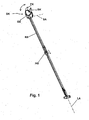
- a hand-held branch cutter which in a conventional manner, a base body with an elongated shaft RS, preferably in the form of a tube or a hollow profile, and at the lower end on the user side along the shank slidable handle HG Includes actuating device.
- a cutting head SK is arranged, which contains a conventional scissors blade assembly BK, FK as a working device.
- the cutting head SK is connected to the shaft RS of the main body via a pivot joint whose pivot axis SA extends transversely to the longitudinal axis LA of the shaft.
- the cutting head SK can be pivoted about the pivot axis SA over a limited pivot angle of advantageously at least 90 °, in particular at least 150 °, and can be used in several different pivot positions for cutting branches.
- a displacement of the handle HG along the shaft is converted by a guided in the interior of the tube tension member by the joint in a cutting movement of the blade assembly.
- Such branch cutters are known per se.
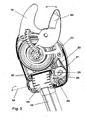
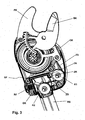
- FIG. 2 the upper end of the shaft RS, the pivot joint and the cutting head is shown in an enlarged view, wherein one of two half-shells of a cutting head housing GE is removed to illustrate essential to the invention parts of the illustrated embodiment.
- a cutter Disposed within the housing GE of the cutting head is a cutter having a stationary blade FK and a movable blade BK, the movable blade being coupled to a toothed arch which engages a rotatable pinion.
- the pinion is rotatably connected to a pulley SS, on which a pull rope ZS up and unwound.
- the pulley assumes under the action of a spring, in particular a coil spring, a rest position, which corresponds to the sketched in Fig. 1 and Fig. 2 open position of the cutting device.
- the housing GE of the cutting head is pivotable about a pivot axis SA via a pivot joint with a joint body GK.
- the joint body GK is mounted for example with axial extensions in the housing GE.
- the traction cable is guided away from the pulley SS, guided over a first roller R1, to a second roller R2 and, after deflection, into the hollow shaft R2 to the spaced actuating device.
- the traction cable extends between the roller R1 and R2 substantially on the pivot axis SA, so that an actuating force transmitted by the traction cable between the rollers R1 and R2 acts only in the axial direction.
- the roller R1 is mounted in a respect to the housing GE of the cutting head fixed bearing, the bearing of the second roller is fixed with respect to the joint body GK.
- the guide of the pull rope in the section between the first and the second roller also has the effect that when pivoting the condyle about the pivot axis no elongation or shortening of the rope occurs and on the other hand.eine transmitted by the tension cable actuation force also causes no torque between the condyle and shaft about the pivot axis.
- the relative to the housing GE of the cutting head about the pivot axis SA pivotally mounted joint body is additionally displaced by a small amount in the axial direction relative to the housing GE of the joint body.
- a gap SP between the joint body and a receptacle in the housing can be seen on the left bearing of the joint body in the housing.
- the axial displaceability of the joint body in the housing is limited by the size of this gap.
- the starting position in which the joint head is pressed to the right under its axial mobility under the influence of an initial holding force, so that the gap SP is free and the condyle is abutted with a contact surface axially opposed to the gap on a mating surface of the articulation in the housing GE.
- the support structure and counterstructure are as sketched advantageously in the manner of a so-called Hirth toothing, ie an axially effective, frontal toothing formed.
- the teeth have oblique tooth flanks, which are inclined both against the circumferential direction of a rotation about the pivot axis SA and against the direction of the pivot axis SA. This results in the possibility that when exercising a torque on the cutting head around the pivot axis due to the oblique course of the tooth flanks of a holding force opposing axial force is created and with sufficiently large torque, the teeth can be pressed apart axially.
- the size of the required torque is in addition to the geometry of the teeth dependent on the size of the holding force.
- An initial holding force without exerting an actuating force on the pull rope can be applied for example by a bias of the pull rope, which shortening the cable section between the two rollers and thus the holding structure and the counter-structure to each other oppressive.
- an initial holding force is applied without the action of an actuating force on the pull rope by a spring which acts axially between housing GE of the cutting head and joint body GK of the body at the end of the shaft RS in the direction that the teeth are pressed into one another by the spring force ,
- a spiral pressure spring RF for this purpose is provided on the side of the joint body GK facing away from the first roller R1.
- the spring force of the spring RF can be chosen so that on the one hand the cutting head is not moved by a separate gravity and / or free movements of the implement from a occupied pivot position, but on the other hand, a manual pivoting of the cutting head about the pivot axis without much effort is possible, in particular in the working position of the device with spaced from the cutting head by the elongated shaft user pivoting about the pivot axis when applying the cutting head to a branch or the like and lateral pressure on the shaft, a change in the pivot position is possible.
- the joint head is displaced relative to the housing of the cutting head along the tooth flanks of the Veryakept.axial, wherein the length of the cable section between the rollers R1 and R2 increases by the depth of the toothing until the tooth tips can slide over one another and slide into the next pivot position defined by the tooth structures.
- a pivoting over a plurality of adjacent pivot positions can be performed in one go.
- the user If the user has set a suitable pivoting position of the cutting head relative to the shaft about the pivot axis in this manner and applied the open edge to a branch to be cut, the user generates an actuating force on the traction cable via the actuating device, which unwinds the traction cable from the sheave and causing the cutter to close.
- An essential feature of the invention when performing the cutting operation is that the two rollers R1 and R2 and because of their fixed storage also condyle GH and housing by the transmitted via the pull cable ZS actuating force, which is effective in the cable section between the rollers R1 and R2 GE of the cutting head in the direction of the pivot axis while reinforcing the holding force in the tooth structures are pressed against each other.
- the operating force is usually much higher than the initial holding force applied by the spring RF, and the holding force during the cutting operation is therefore advantageously given during the cutting operation by the actuating force. This ensures that during the cutting process, the user selected pivot position and position on the branch does not change unintentionally, which is also important from the point of view that there is often the risk of such a shift by a high actuation force.
Landscapes
- Life Sciences & Earth Sciences (AREA)
- Biodiversity & Conservation Biology (AREA)
- Ecology (AREA)
- Forests & Forestry (AREA)
- Environmental Sciences (AREA)
- Harvester Elements (AREA)
- Scissors And Nippers (AREA)
Applications Claiming Priority (1)
| Application Number | Priority Date | Filing Date | Title |
|---|---|---|---|
| DE200610039218 DE102006039218A1 (de) | 2006-08-22 | 2006-08-22 | Handhaltbares Arbeitsgerät, insbesondere Astschneider |
Publications (2)
| Publication Number | Publication Date |
|---|---|
| EP1891853A1 true EP1891853A1 (fr) | 2008-02-27 |
| EP1891853B1 EP1891853B1 (fr) | 2013-07-24 |
Family
ID=38691849
Family Applications (1)
| Application Number | Title | Priority Date | Filing Date |
|---|---|---|---|
| EP20070016038 Active EP1891853B1 (fr) | 2006-08-22 | 2007-08-16 | Appareil de travail pouvant être tenu à la main, en particulier dispositif de découpe de branches |
Country Status (2)
| Country | Link |
|---|---|
| EP (1) | EP1891853B1 (fr) |
| DE (1) | DE102006039218A1 (fr) |
Cited By (11)
| Publication number | Priority date | Publication date | Assignee | Title |
|---|---|---|---|---|
| EP2319295A1 (fr) * | 2009-11-06 | 2011-05-11 | Natura Innovation Ltd. | Sécateur à longue portée |
| WO2013091681A1 (fr) | 2011-12-20 | 2013-06-27 | Gardena Manufacturing Gmbh | Tête d'ébrancheur et ébrancheur |
| CN105660208A (zh) * | 2016-02-25 | 2016-06-15 | 芜湖新达园林绿化集团有限公司 | 一种新型树木修剪装置 |
| CN106664965A (zh) * | 2017-02-24 | 2017-05-17 | 中国农业大学 | 一种基于负压吸力的便携式苹果采摘装置 |
| CN108391510A (zh) * | 2018-04-28 | 2018-08-14 | 温州大学 | 一种樱桃采摘分拣装置 |
| CN108476736A (zh) * | 2018-05-23 | 2018-09-04 | 吉林农业科技学院 | 一种苹果采摘器 |
| CN108633474A (zh) * | 2018-04-23 | 2018-10-12 | 青岛理工大学 | 定力矩苹果采摘机械手 |
| CN109924007A (zh) * | 2019-04-30 | 2019-06-25 | 清华大学天津高端装备研究院洛阳先进制造产业研发基地 | 可伸缩便捷式水果采摘器 |
| CN110506500A (zh) * | 2019-09-30 | 2019-11-29 | 华中农业大学 | 一种单手采摘柑橘的装置 |
| CN113330936A (zh) * | 2021-05-26 | 2021-09-03 | 唐继红 | 一种便携式生态果园果树养护剪枝装置 |
| CN113906904A (zh) * | 2021-11-22 | 2022-01-11 | 塔里木大学 | 一种手持型仿生采摘器 |
Families Citing this family (3)
| Publication number | Priority date | Publication date | Assignee | Title |
|---|---|---|---|---|
| CN103168561B (zh) * | 2013-03-29 | 2016-05-04 | 湖北四季春茶油股份有限公司 | 一种油茶摘果机 |
| CN105191578A (zh) * | 2015-11-12 | 2015-12-30 | 王立云 | 一种盲人导航的水果采摘器 |
| US12508720B2 (en) | 2022-10-07 | 2025-12-30 | Kubota Corporation | End effector including cutting blade and pulley assembly |
Citations (4)
| Publication number | Priority date | Publication date | Assignee | Title |
|---|---|---|---|---|
| DE949784C (de) * | 1954-07-21 | 1956-09-27 | Georg Morell | Stielbaumschere |
| DE3925752A1 (de) * | 1989-08-03 | 1991-02-07 | Wolf Geraete Gmbh | Baumschere |
| EP0895712A1 (fr) * | 1997-08-07 | 1999-02-10 | Fiskars Consumer Oy Ab | Sécateur |
| DE102005039084A1 (de) * | 2005-08-05 | 2007-02-08 | Gardena Manufacturing Gmbh | Schere zum Schneiden von Ästen |
Family Cites Families (2)
| Publication number | Priority date | Publication date | Assignee | Title |
|---|---|---|---|---|
| DE1681329U (de) * | 1954-03-18 | 1954-08-12 | George Morell | Stielbaumschere. |
| DE1911737A1 (de) * | 1969-03-07 | 1970-09-24 | Leyat Pierre | Geraet zum Baumausschneiden |
-
2006
- 2006-08-22 DE DE200610039218 patent/DE102006039218A1/de not_active Withdrawn
-
2007
- 2007-08-16 EP EP20070016038 patent/EP1891853B1/fr active Active
Patent Citations (4)
| Publication number | Priority date | Publication date | Assignee | Title |
|---|---|---|---|---|
| DE949784C (de) * | 1954-07-21 | 1956-09-27 | Georg Morell | Stielbaumschere |
| DE3925752A1 (de) * | 1989-08-03 | 1991-02-07 | Wolf Geraete Gmbh | Baumschere |
| EP0895712A1 (fr) * | 1997-08-07 | 1999-02-10 | Fiskars Consumer Oy Ab | Sécateur |
| DE102005039084A1 (de) * | 2005-08-05 | 2007-02-08 | Gardena Manufacturing Gmbh | Schere zum Schneiden von Ästen |
Cited By (16)
| Publication number | Priority date | Publication date | Assignee | Title |
|---|---|---|---|---|
| EP2319295A1 (fr) * | 2009-11-06 | 2011-05-11 | Natura Innovation Ltd. | Sécateur à longue portée |
| US20110107606A1 (en) * | 2009-11-06 | 2011-05-12 | Su-Hua Shan | Long reach pruner |
| WO2013091681A1 (fr) | 2011-12-20 | 2013-06-27 | Gardena Manufacturing Gmbh | Tête d'ébrancheur et ébrancheur |
| CN105660208A (zh) * | 2016-02-25 | 2016-06-15 | 芜湖新达园林绿化集团有限公司 | 一种新型树木修剪装置 |
| CN106664965B (zh) * | 2017-02-24 | 2022-10-25 | 中国农业大学 | 一种基于负压吸力的便携式苹果采摘装置 |
| CN106664965A (zh) * | 2017-02-24 | 2017-05-17 | 中国农业大学 | 一种基于负压吸力的便携式苹果采摘装置 |
| CN108633474A (zh) * | 2018-04-23 | 2018-10-12 | 青岛理工大学 | 定力矩苹果采摘机械手 |
| CN108391510A (zh) * | 2018-04-28 | 2018-08-14 | 温州大学 | 一种樱桃采摘分拣装置 |
| CN108391510B (zh) * | 2018-04-28 | 2023-05-16 | 温州大学 | 一种樱桃采摘分拣装置 |
| CN108476736A (zh) * | 2018-05-23 | 2018-09-04 | 吉林农业科技学院 | 一种苹果采摘器 |
| CN109924007A (zh) * | 2019-04-30 | 2019-06-25 | 清华大学天津高端装备研究院洛阳先进制造产业研发基地 | 可伸缩便捷式水果采摘器 |
| CN109924007B (zh) * | 2019-04-30 | 2024-05-28 | 清研(洛阳)先进制造产业研究院 | 可伸缩便捷式水果采摘器 |
| CN110506500A (zh) * | 2019-09-30 | 2019-11-29 | 华中农业大学 | 一种单手采摘柑橘的装置 |
| CN110506500B (zh) * | 2019-09-30 | 2024-03-15 | 华中农业大学 | 一种单手采摘柑橘的装置 |
| CN113330936A (zh) * | 2021-05-26 | 2021-09-03 | 唐继红 | 一种便携式生态果园果树养护剪枝装置 |
| CN113906904A (zh) * | 2021-11-22 | 2022-01-11 | 塔里木大学 | 一种手持型仿生采摘器 |
Also Published As
| Publication number | Publication date |
|---|---|
| DE102006039218A1 (de) | 2008-02-28 |
| EP1891853B1 (fr) | 2013-07-24 |
Similar Documents
| Publication | Publication Date | Title |
|---|---|---|
| EP1891853B1 (fr) | Appareil de travail pouvant être tenu à la main, en particulier dispositif de découpe de branches | |
| DE102007049032B4 (de) | Zange | |
| EP1464289B1 (fr) | Instrument chirurgical, dans lequel les mouvements de la tête et de l'outil sont découplés | |
| DE69800491T2 (de) | Baumschere | |
| EP2241403B1 (fr) | Outil de manipulation et outil pour fixer et/ou écarter avec au moins un outil de manipulation | |
| DE19615241C1 (de) | Chirurgischer Drehmomentschlüssel | |
| EP2900397B2 (fr) | Outil élargisseur à main | |
| DE102012212510B4 (de) | Endoskopisches Instrument | |
| EP3020346B1 (fr) | Dispositif médical | |
| DE2402187A1 (de) | Geraet zum abstreifen der verkleidung von bezogenen leitungen und dgl. | |
| DE202008001675U1 (de) | Zerlegbares chirurgisches Instrument | |
| EP1052945A1 (fr) | Instrument medical a tige tubulaire | |
| EP0940203A2 (fr) | Outil de rivetage à main pour rivets aveugles | |
| WO2010118831A1 (fr) | Instrument chirurgical démontable | |
| EP1625784A1 (fr) | Outil de coupe manuel, en particulier un taille-haie ou sécateur | |
| DE19906360B4 (de) | Chirurgisches Rohrschaftinstrument | |
| WO2019223992A1 (fr) | Clé à cliquet | |
| DE102010007917B4 (de) | Handbetätigtes Werkzeug | |
| DE10130452B4 (de) | Handhaltbares Arbeitsgerät in Form einer Baumschere | |
| DE102009047781B4 (de) | Vorrichtung zum Bearbeiten stabförmiger Elemente | |
| EP3210724A2 (fr) | Outil presentant un systeme de reglage de largeur de poignee | |
| EP2229110B1 (fr) | Dispositif rapporté pour dispositif chirurgical et dispositif chirurgical correspondant pour percer un os | |
| DE102013105240A1 (de) | Stabhaltezange mit Winkelverstellung | |
| EP2314151B1 (fr) | Cisailles destinées à couper des branches | |
| DE202014004160U1 (de) | Rohrschaftinstrument |
Legal Events
| Date | Code | Title | Description |
|---|---|---|---|
| PUAI | Public reference made under article 153(3) epc to a published international application that has entered the european phase |
Free format text: ORIGINAL CODE: 0009012 |
|
| AK | Designated contracting states |
Kind code of ref document: A1 Designated state(s): AT BE BG CH CY CZ DE DK EE ES FI FR GB GR HU IE IS IT LI LT LU LV MC MT NL PL PT RO SE SI SK TR |
|
| AX | Request for extension of the european patent |
Extension state: AL BA HR MK YU |
|
| 17P | Request for examination filed |
Effective date: 20080814 |
|
| AKX | Designation fees paid |
Designated state(s): AT BE BG CH CY CZ DE DK EE ES FI FR GB GR HU IE IS IT LI LT LU LV MC MT NL PL PT RO SE SI SK TR |
|
| GRAP | Despatch of communication of intention to grant a patent |
Free format text: ORIGINAL CODE: EPIDOSNIGR1 |
|
| GRAS | Grant fee paid |
Free format text: ORIGINAL CODE: EPIDOSNIGR3 |
|
| GRAA | (expected) grant |
Free format text: ORIGINAL CODE: 0009210 |
|
| RAP1 | Party data changed (applicant data changed or rights of an application transferred) |
Owner name: HUSQVARNA AB |
|
| AK | Designated contracting states |
Kind code of ref document: B1 Designated state(s): AT BE BG CH CY CZ DE DK EE ES FI FR GB GR HU IE IS IT LI LT LU LV MC MT NL PL PT RO SE SI SK TR |
|
| REG | Reference to a national code |
Ref country code: GB Ref legal event code: FG4D Free format text: NOT ENGLISH |
|
| REG | Reference to a national code |
Ref country code: CH Ref legal event code: EP |
|
| REG | Reference to a national code |
Ref country code: AT Ref legal event code: REF Ref document number: 622856 Country of ref document: AT Kind code of ref document: T Effective date: 20130815 |
|
| REG | Reference to a national code |
Ref country code: IE Ref legal event code: FG4D Free format text: LANGUAGE OF EP DOCUMENT: GERMAN |
|
| REG | Reference to a national code |
Ref country code: DE Ref legal event code: R096 Ref document number: 502007012067 Country of ref document: DE Effective date: 20130919 |
|
| REG | Reference to a national code |
Ref country code: NL Ref legal event code: VDEP Effective date: 20130724 |
|
| REG | Reference to a national code |
Ref country code: LT Ref legal event code: MG4D |
|
| PG25 | Lapsed in a contracting state [announced via postgrant information from national office to epo] |
Ref country code: PT Free format text: LAPSE BECAUSE OF FAILURE TO SUBMIT A TRANSLATION OF THE DESCRIPTION OR TO PAY THE FEE WITHIN THE PRESCRIBED TIME-LIMIT Effective date: 20131125 Ref country code: IS Free format text: LAPSE BECAUSE OF FAILURE TO SUBMIT A TRANSLATION OF THE DESCRIPTION OR TO PAY THE FEE WITHIN THE PRESCRIBED TIME-LIMIT Effective date: 20131124 Ref country code: SE Free format text: LAPSE BECAUSE OF FAILURE TO SUBMIT A TRANSLATION OF THE DESCRIPTION OR TO PAY THE FEE WITHIN THE PRESCRIBED TIME-LIMIT Effective date: 20130724 Ref country code: CY Free format text: LAPSE BECAUSE OF FAILURE TO SUBMIT A TRANSLATION OF THE DESCRIPTION OR TO PAY THE FEE WITHIN THE PRESCRIBED TIME-LIMIT Effective date: 20130703 Ref country code: LT Free format text: LAPSE BECAUSE OF FAILURE TO SUBMIT A TRANSLATION OF THE DESCRIPTION OR TO PAY THE FEE WITHIN THE PRESCRIBED TIME-LIMIT Effective date: 20130724 |
|
| BERE | Be: lapsed |
Owner name: HUSQVARNA A.B. Effective date: 20130831 |
|
| PG25 | Lapsed in a contracting state [announced via postgrant information from national office to epo] |
Ref country code: PL Free format text: LAPSE BECAUSE OF FAILURE TO SUBMIT A TRANSLATION OF THE DESCRIPTION OR TO PAY THE FEE WITHIN THE PRESCRIBED TIME-LIMIT Effective date: 20130724 Ref country code: SI Free format text: LAPSE BECAUSE OF FAILURE TO SUBMIT A TRANSLATION OF THE DESCRIPTION OR TO PAY THE FEE WITHIN THE PRESCRIBED TIME-LIMIT Effective date: 20130724 Ref country code: GR Free format text: LAPSE BECAUSE OF FAILURE TO SUBMIT A TRANSLATION OF THE DESCRIPTION OR TO PAY THE FEE WITHIN THE PRESCRIBED TIME-LIMIT Effective date: 20131025 Ref country code: NL Free format text: LAPSE BECAUSE OF FAILURE TO SUBMIT A TRANSLATION OF THE DESCRIPTION OR TO PAY THE FEE WITHIN THE PRESCRIBED TIME-LIMIT Effective date: 20130724 Ref country code: LV Free format text: LAPSE BECAUSE OF FAILURE TO SUBMIT A TRANSLATION OF THE DESCRIPTION OR TO PAY THE FEE WITHIN THE PRESCRIBED TIME-LIMIT Effective date: 20130724 |
|
| PG25 | Lapsed in a contracting state [announced via postgrant information from national office to epo] |
Ref country code: CY Free format text: LAPSE BECAUSE OF FAILURE TO SUBMIT A TRANSLATION OF THE DESCRIPTION OR TO PAY THE FEE WITHIN THE PRESCRIBED TIME-LIMIT Effective date: 20130724 |
|
| PG25 | Lapsed in a contracting state [announced via postgrant information from national office to epo] |
Ref country code: EE Free format text: LAPSE BECAUSE OF FAILURE TO SUBMIT A TRANSLATION OF THE DESCRIPTION OR TO PAY THE FEE WITHIN THE PRESCRIBED TIME-LIMIT Effective date: 20130724 Ref country code: SK Free format text: LAPSE BECAUSE OF FAILURE TO SUBMIT A TRANSLATION OF THE DESCRIPTION OR TO PAY THE FEE WITHIN THE PRESCRIBED TIME-LIMIT Effective date: 20130724 Ref country code: MC Free format text: LAPSE BECAUSE OF FAILURE TO SUBMIT A TRANSLATION OF THE DESCRIPTION OR TO PAY THE FEE WITHIN THE PRESCRIBED TIME-LIMIT Effective date: 20130724 Ref country code: DK Free format text: LAPSE BECAUSE OF FAILURE TO SUBMIT A TRANSLATION OF THE DESCRIPTION OR TO PAY THE FEE WITHIN THE PRESCRIBED TIME-LIMIT Effective date: 20130724 Ref country code: CZ Free format text: LAPSE BECAUSE OF FAILURE TO SUBMIT A TRANSLATION OF THE DESCRIPTION OR TO PAY THE FEE WITHIN THE PRESCRIBED TIME-LIMIT Effective date: 20130724 Ref country code: RO Free format text: LAPSE BECAUSE OF FAILURE TO SUBMIT A TRANSLATION OF THE DESCRIPTION OR TO PAY THE FEE WITHIN THE PRESCRIBED TIME-LIMIT Effective date: 20130724 |
|
| REG | Reference to a national code |
Ref country code: IE Ref legal event code: MM4A |
|
| PG25 | Lapsed in a contracting state [announced via postgrant information from national office to epo] |
Ref country code: ES Free format text: LAPSE BECAUSE OF FAILURE TO SUBMIT A TRANSLATION OF THE DESCRIPTION OR TO PAY THE FEE WITHIN THE PRESCRIBED TIME-LIMIT Effective date: 20130724 Ref country code: IT Free format text: LAPSE BECAUSE OF FAILURE TO SUBMIT A TRANSLATION OF THE DESCRIPTION OR TO PAY THE FEE WITHIN THE PRESCRIBED TIME-LIMIT Effective date: 20130724 Ref country code: BE Free format text: LAPSE BECAUSE OF NON-PAYMENT OF DUE FEES Effective date: 20130831 |
|
| PLBE | No opposition filed within time limit |
Free format text: ORIGINAL CODE: 0009261 |
|
| STAA | Information on the status of an ep patent application or granted ep patent |
Free format text: STATUS: NO OPPOSITION FILED WITHIN TIME LIMIT |
|
| GBPC | Gb: european patent ceased through non-payment of renewal fee |
Effective date: 20131024 |
|
| 26N | No opposition filed |
Effective date: 20140425 |
|
| PG25 | Lapsed in a contracting state [announced via postgrant information from national office to epo] |
Ref country code: GB Free format text: LAPSE BECAUSE OF NON-PAYMENT OF DUE FEES Effective date: 20131024 Ref country code: IE Free format text: LAPSE BECAUSE OF NON-PAYMENT OF DUE FEES Effective date: 20130816 |
|
| REG | Reference to a national code |
Ref country code: DE Ref legal event code: R097 Ref document number: 502007012067 Country of ref document: DE Effective date: 20140425 |
|
| PG25 | Lapsed in a contracting state [announced via postgrant information from national office to epo] |
Ref country code: MT Free format text: LAPSE BECAUSE OF FAILURE TO SUBMIT A TRANSLATION OF THE DESCRIPTION OR TO PAY THE FEE WITHIN THE PRESCRIBED TIME-LIMIT Effective date: 20130724 Ref country code: TR Free format text: LAPSE BECAUSE OF FAILURE TO SUBMIT A TRANSLATION OF THE DESCRIPTION OR TO PAY THE FEE WITHIN THE PRESCRIBED TIME-LIMIT Effective date: 20130724 |
|
| REG | Reference to a national code |
Ref country code: FR Ref legal event code: PLFP Year of fee payment: 9 |
|
| PG25 | Lapsed in a contracting state [announced via postgrant information from national office to epo] |
Ref country code: LU Free format text: LAPSE BECAUSE OF NON-PAYMENT OF DUE FEES Effective date: 20130816 Ref country code: HU Free format text: LAPSE BECAUSE OF FAILURE TO SUBMIT A TRANSLATION OF THE DESCRIPTION OR TO PAY THE FEE WITHIN THE PRESCRIBED TIME-LIMIT; INVALID AB INITIO Effective date: 20070816 Ref country code: BG Free format text: LAPSE BECAUSE OF FAILURE TO SUBMIT A TRANSLATION OF THE DESCRIPTION OR TO PAY THE FEE WITHIN THE PRESCRIBED TIME-LIMIT Effective date: 20130724 |
|
| PGFP | Annual fee paid to national office [announced via postgrant information from national office to epo] |
Ref country code: CH Payment date: 20150805 Year of fee payment: 9 |
|
| PGFP | Annual fee paid to national office [announced via postgrant information from national office to epo] |
Ref country code: AT Payment date: 20150727 Year of fee payment: 9 |
|
| REG | Reference to a national code |
Ref country code: FR Ref legal event code: PLFP Year of fee payment: 10 |
|
| REG | Reference to a national code |
Ref country code: CH Ref legal event code: PL |
|
| REG | Reference to a national code |
Ref country code: AT Ref legal event code: MM01 Ref document number: 622856 Country of ref document: AT Kind code of ref document: T Effective date: 20160816 |
|
| PG25 | Lapsed in a contracting state [announced via postgrant information from national office to epo] |
Ref country code: CH Free format text: LAPSE BECAUSE OF NON-PAYMENT OF DUE FEES Effective date: 20160831 Ref country code: LI Free format text: LAPSE BECAUSE OF NON-PAYMENT OF DUE FEES Effective date: 20160831 |
|
| PG25 | Lapsed in a contracting state [announced via postgrant information from national office to epo] |
Ref country code: AT Free format text: LAPSE BECAUSE OF NON-PAYMENT OF DUE FEES Effective date: 20160816 |
|
| REG | Reference to a national code |
Ref country code: FR Ref legal event code: PLFP Year of fee payment: 11 |
|
| REG | Reference to a national code |
Ref country code: FR Ref legal event code: PLFP Year of fee payment: 12 |
|
| P01 | Opt-out of the competence of the unified patent court (upc) registered |
Effective date: 20230419 |
|
| PGFP | Annual fee paid to national office [announced via postgrant information from national office to epo] |
Ref country code: FI Payment date: 20230717 Year of fee payment: 17 |
|
| PGFP | Annual fee paid to national office [announced via postgrant information from national office to epo] |
Ref country code: FR Payment date: 20230706 Year of fee payment: 17 |
|
| PG25 | Lapsed in a contracting state [announced via postgrant information from national office to epo] |
Ref country code: FI Free format text: LAPSE BECAUSE OF NON-PAYMENT OF DUE FEES Effective date: 20240816 |
|
| PG25 | Lapsed in a contracting state [announced via postgrant information from national office to epo] |
Ref country code: FR Free format text: LAPSE BECAUSE OF NON-PAYMENT OF DUE FEES Effective date: 20240831 |
|
| PGFP | Annual fee paid to national office [announced via postgrant information from national office to epo] |
Ref country code: DE Payment date: 20250708 Year of fee payment: 19 |